


w w w . m g e u p s . c o m
Standard Features
Epsilon 200A System
Epsilon 400A/600A System
Epsilon STSTM
200A and 400A/600A Static Transfer Switch
Installation and User Manual
86-504004-00 B03

Installation and User Manual
Epsilon STSTM
200A and 400A/600A Static Transfer Switch
Installation and User manual
Revision History
Epsilon STS 200A and 400A/600A STS, Installation and User Manual 86-12345-00 B02
Revision: |
A00 |
Initial Release |
06/2002 |
|
B00 |
ECN: 002866 |
09/2002 |
|
B01 |
ECN:#003777 |
03/2004 |
|
B02 |
ECN:#004471 |
07/2005 |
|
B03 |
ECN:#004991 |
10/2006 |
Copyright © 2005 MGE UPS SYSTEMS, INC.
All rights reserved. Printed in U.S.A.
MGE UPS SYSTEMS, INC.
1660 Scenic Avenue Costa Mesa, CA 92626 (714) 557-1636
Technical Support:
1-800-523-0142 (during business hours)
Customer Care Center: 1-800-438-7373 (Hours: 24/7)
86-504004-00 B03 |
Chaptername |
i |

Epilson STSTM
IMPORTANT SAFETY INSTRUCTIONS
SAVE THESE INSTRUCTIONS – This manual contains important instructions for the Epsilon STSTM that must be followed during operation of the equipment.
WARNING |
Opening enclosures expose hazardous voltages. Always refer service to |
|
|
|
qualified personnel only. |
ATTENTION |
|
L'ouverture des cabinets expose des tensions dangereuses. Assurez-vous |
|
|
toujours que le service ne soit fait que par des personnes qualifiees. |
WARNUNG! |
|
Das öffnen der Gehäuse legen gefährliche Spannungen bloss. Service |
|
|
sollte immer nur von qualifizierten Personal durchgeführt werden. |
|
|
|
|
|
|
WARNING |
|
As standards, specifications, and designs are subject to change, please |
|
|
ask for confirmation of the information given in this publication. |
ATTENTION |
|
Comme les normes, spécifications et produits peuvent changer, veuillez |
|
|
demander confirmation des informations contenues dans cette publication. |
WARNUNG! |
|
Normen, Spezifizierungen und Pläne unterliegen Anderungen. Bitte verlan- |
|
|
gen Sie eine Bestätigung über alle Informationen, die in dieser Ausgabe |
|
|
gemacht wurden. |
NOTE |
|
|
|
|
|
|
This equipment has been tested and found to comply with the limits for a |
|
|
|
Class A digital device, pursuant to part 15 of the FCC rules. These limits |
|
|
are designed to provide reasonable protection against harmful interference |
|
|
when the equipment is operated in a commercial environment. |
|
|
This equipment generates, uses, and can radiate radio frequency energy |
|
|
and, if not installed and used in accordance with the instruction manual, |
|
|
may cause harmful interference to radio communications. Operation of |
|
|
this equipment in a residential area is likely to cause harmful interference |
|
|
in which case the user will be required to correct the interference at user's |
|
|
own expense. |
|
|
|
Certification Standards
IEEE 587-1980/ANSI C62.41 for Cat. B3, 1980 Standards for Surge Withstand Ability
FCC rules and regulations of Part 15, Subpart J, Class A , EN50081-2 (use shielded cables)
UL listed under 1008, Standards for Transfer Switch Equipment.
NEMA PE 1 (National Electrical Manufacturers Association) - Uninterruptible Power Systems
NEMA 250 (National Electrical Manufacturers Association)
– Enclosures for Electrical Equipment (1000 Volts Maximum)
NFPA 70 – National Electrical Code
ISO 9001 Quality Assurance, NEC, ANSI, NEMA, NFPA, IEEE.
Occupational Safety & Health Administration (OSHA)
ii |
Important Safety Information and Standards |
86-504004-00 B03 |

Installation and User Manual
WARNING |
To reduce the risk of fire or electric shock, install in a temperature and |
|
|
humidity controlled indoor area free of conductive contaminant’s. |
|
|
This equipment is intended only for installations in a RESTRICTED |
|
|
ACCESS LOCATION. |
|
ATTENTION |
Pour réduire le riske d'inccendie ou d'électrocution, installer dans une |
|
|
|
enciente intérieure contrôlée en température et humidité et sans |
|
|
contaminant’s conducteurs. |
|
Ce matériel est destiné seulement pour des installations dans un |
|
|
EMPLACEMENT RESTREINT d'accès. |
|
WARNUNG! |
Um die Gefahr von Feuer und elektrischem Schock zu reduzieren, muss |
|
|
das Gerät in einem temperatur - und feuchtigkeitskontrollierten Raum, frei |
|
|
von leitungsfähigen Verunreinigungen, installiert werden. Dieses Gerät ist |
|
|
nur für die Installation an einem Ort mit eingeschränkter Zugangserlaubnis |
|
|
vorgesehen. |
|
|
Diese Ausrüstung ist nur für Anlagen in einem EINGESCHRäNKTEN |
|
|
ZUGRIFF STANDORT bestimmti. |
|
|
|
|
|
|
|
WARNING |
HIGH LEAKAGE CURRENT. Earth connection essential before |
|
|
|
connecting supply. |
ATTENTION |
COURANT DE FUITE ELEVE. Raccordement a la terre indispensable |
|
|
|
avant le raccordement au reseau. |
WARNUNG! Hoher Ableitstrom Vor Inbetriebnahme Schutzleiterverbindung
herstellen.
How to use this manual and Symbol Usage
This manual is designed for ease of use and easy location of information.
This manual uses four icon symbols with text to convey important information and tips.
WARNING Indicates information provided to protect the user and service personnel against safety hazards and/or possible equipment damage.
|
|
|
|
CAUTION |
Indicates information provided to protect the user and service personnel against possible |
|
|
|
|
|
equipment damage. |
|
|
|
|
|
|
|
|
|
|
|
|
|
|
|
|
IMPORTANT |
Indicates information provided as an operating instruction, or as an operating tip. |
|
|
|
|||
|
|
|
|
NOTE |
|
|
|
|
|
|
|
|
|
|
|
|
|
|
|
|
|
Indicates information provided as an operating tip or an equipment feature. |
|
|
|
|
|
||
|
|
|
|
|
|
86-504004-00 B03 |
How To Use This Manual and Symbol Usage |
iii |

Epilson STSTM
CAUTION: Record All Serial Numbers!
RECORD ALL SERIAL NUMBERS FOR THE Epilson STSTM AND COMPONENTS. THESE SERIAL NUMBERS WILL BE REQUIRED IF YOUR SYSTEM NEEDS SERVICE. KEEP THIS MANUAL IN A PLACE WHERE YOU CAN REFERENCE THE SERIAL NUMBERS IF SERVICE IS REQUIRED!
UPS SERIAL NUMBER: _______________________________________________________
MODULE SERIAL NUMBER: ____________________________________________________
BATTERY SERIAL NUMBER: ___________________________________________________
ADDITIONAL MODULES SERIAL NUMBERS:
____________________________ ______________________________
____________________________ ______________________________
____________________________ ______________________________
____________________________ ______________________________
____________________________ ______________________________
____________________________ ______________________________
____________________________ ______________________________
____________________________ ______________________________
____________________________ ______________________________
____________________________ ______________________________
iv |
CAUTION: Record All Serial Numbers |
86-504004-00 B03 |

Contents
section |
description . . . . . . . . . . . . . . . . . . . . . . . . . . . . . . . . . . . . . . . . . . . |
page |
|
Revision History . . . . . . . . . . . . . . . . . . . . . . . . . . . . . . . . . . . . . . |
. . . .i |
|
IMPORTANT SAFETY INSTRUCTIONS . . . . . . . . . . . . . . . . . . . . |
. . .ii |
|
Certification Standards . . . . . . . . . . . . . . . . . . . . . . . . . . . . . . . . . |
. . .ii |
|
How to use this manual and Symbol Usage . . . . . . . . . . . . . . . . . |
. . .iii |
|
CAUTION: Record All Serial Numbers! . . . . . . . . . . . . . . . . . . . . |
. . .iv |
Quick Start
section |
description . . . . . . . . . . . . . . . . . . . . . . . . . . . . . . . . . . . . . . . . . |
. .page |
|
First steps by an on-site qualified Technical Engineer . . . . . . . . . . . . . |
QS —1 |
||
Required Equipment and Tools . . . . . . . . . . . . . . . . . . . . . . . . . . . . . . . |
QS —1 |
||
Step |
1 |
Unpacking . . . . . . . . . . . . . . . . . . . . . . . . . . . . . . . . . . . . . . . |
QS —2 |
Step |
2 |
Connection of Utility Power Inputs . . . . . . . . . . . . . . . . . . . . . |
QS —4 |
|
Connect Input Power from Two Sources . . . . . . . . . . . . . . . . |
QS —4 |
|
Step |
3 |
Connection of the Load Outputs . . . . . . . . . . . . . . . . . . . . . . |
QS —4 |
Step |
4 |
Call MGE UPS Systems for Field Engineer Service . . . . . . |
QS —5 |
Step |
5 Arrival of MGE Field Engineer . . . . . . . . . . . . . . . . . . . . . . . . |
QS —5 |
|
Optional Steps . . . . . . . . . . . . . . . . . . . . . . . . . . . . . . . . . . . . . . . . . . . . |
QS —6 |
||
Section 1 Introduction
section |
description . . . . . . . . . . . . . . . . . . . . . . . . . . . . . . . . . . . . . . . . . |
. .page |
1.0 |
Scope . . . . . . . . . . . . . . . . . . . . . . . . . . . . . . . . . . . . . . . . . . . . |
.1 — 1 |
1.1 |
Reference Manuals . . . . . . . . . . . . . . . . . . . . . . . . . . . . . . . . . . |
.1 — 1 |
1.2 |
Section Descriptions . . . . . . . . . . . . . . . . . . . . . . . . . . . . . . . . . |
.1 — 1 |
1.3 |
General Description . . . . . . . . . . . . . . . . . . . . . . . . . . . . . . . . . . |
.1 — 2 |
1.4 |
Epsilon STSTM System Characteristics . . . . . . . . . . . . . . . . . . |
.1 — 3 |
1.4.1 |
PMM2 Plus and PMM2 Ultra . . . . . . . . . . . . . . . . . . . . . . . . . . . |
.1 — 4 |
1.5 |
System Major Components . . . . . . . . . . . . . . . . . . . . . . . . . . . . |
.1 — 5 |
1.6 |
Single Line Diagram . . . . . . . . . . . . . . . . . . . . . . . . . . . . . . . . . |
.1 — 7 |
1.7 |
System Specifications . . . . . . . . . . . . . . . . . . . . . . . . . . . . . . . . |
.1 — 8 |
1.7.1 |
Electrical Electrical Characteristics . . . . . . . . . . . . . . . . . . . . . . |
.1 — 8 |
1.7.2 |
Electrical Cable Access and Connections . . . . . . . . . . . . . . . . . |
.1 — 9 |
1.7.3 |
Connecting Power Cables . . . . . . . . . . . . . . . . . . . . . . . . . . . . |
.1 — 9 |
1.7.4 |
Accessing Electrical Connections . . . . . . . . . . . . . . . . . . . . . . . |
1 — 10 |
86-504004-00 B03 |
Contents |
c i |

Epilson STSTM
Section 2 Setup and Installation
section |
description . . . . . . . . . . . . . . . . . . . . . . . . . . . . . . . . . . . . . . . |
. . . .page |
|
2.0 |
Scope . . . . . . . . . . . . . . . . . . . . . . . . . . . . . . . . . . . . . . . . . . |
. . .2 |
— 1 |
|
First steps by an on-site qualified Technical Engineer . . . . . . |
. .2 |
— 1 |
|
Final steps by MGE Field Service Engineer . . . . . . . . . . . . . . |
. .2 |
— 1 |
|
Required Equipment and Tools . . . . . . . . . . . . . . . . . . . . . . . . |
. .2 |
— 1 |
2.1 |
Cabinet Placement and Environment . . . . . . . . . . . . . . . . . . . |
. .2 |
— 2 |
2.2 |
Clearances and FootPrint . . . . . . . . . . . . . . . . . . . . . . . . . . . . |
. .2 |
— 2 |
2.2.1 |
Conduit Plate Location (bottom entry) . . . . . . . . . . . . . . . . . . . |
. .2 |
— 3 |
2.3 |
Source #1 AC Input Connections . . . . . . . . . . . . . . . . . . . . . . |
. .2 |
— 3 |
2.3.1. |
Source #2 AC Input Connections . . . . . . . . . . . . . . . . . . . . . . |
. .2 |
— 3 |
2.3.2 |
AC Output Connections . . . . . . . . . . . . . . . . . . . . . . . . . . . . . . |
. .2 |
— 3 |
2.3.3 |
Remote Emergency Power Off (REPO) Cable Connections |
. . .2 — 4 |
|
2.3.4 |
Remote Source Loss Test Cable Connections . . . . . . . . . . . . |
. .2 — 4 |
|
2.3.5 |
Connection of the Relay Communication Card . . . . . . . . . . . . |
. .2 — 5 |
|
2.3.6 |
Characteristics of the Output Contacts . . . . . . . . . . . . . . . . . . |
. .2 — 6 |
|
2.3.7 |
Characteristics of the Input Contacts . . . . . . . . . . . . . . . . . . . |
. .2 — 6 |
|
2.3.8 |
Removing the Communications Card Cover . . . . . . . . . . . . . . |
. .2 — 7 |
|
2.3.9 |
Replacing the Cover . . . . . . . . . . . . . . . . . . . . . . . . . . . . . . . . |
. .2 — 7 |
|
2.4 |
Setting Operation Mode . . . . . . . . . . . . . . . . . . . . . . . . . . . . . |
. .2 — 8 |
|
2.5Setting the Output Relay Contacts and Inputs Switching States 2 — 9
|
2.5.1 Connection of the JBUS Communication Card . . . . . . . . . . . . |
.2 — 10 |
|
2.6 |
|
Check Points Before and After Start Up . . . . . . . . . . . . . . . . . |
.2 — 10 |
|
2.6.1 |
Pre-Start Up Safety Check List . . . . . . . . . . . . . . . . . . . . . . . |
.2 — 10 |
|
2.6.2 |
Post-Start Up Safety Check List . . . . . . . . . . . . . . . . . . . . . . . . |
2 — 10 |
Section 3 Operation
section |
description . . . . . . . . . . . . . . . . . . . . . . . . . . . . . . . . . . . . . . . . . . |
.page |
|
3.0 |
Scope . . . . . . . . . . . . . . . . . . . . . . . . . . . . . . . . . . . . . . . . . . . . . |
.3 |
—1 |
3.1 |
Preparation for Operation . . . . . . . . . . . . . . . . . . . . . . . . . . . . . . |
.3 |
—1 |
3.2 |
Pre-Start Up Safety Check List . . . . . . . . . . . . . . . . . . . . . . . . . |
.3 |
—1 |
3.2.1 |
Normal Start Up Procedure . . . . . . . . . . . . . . . . . . . . . . . . . . . . |
.3 |
—2 |
3.2.2 |
Post Start Up Safety Check List . . . . . . . . . . . . . . . . . . . . . . . . . |
.3 |
—3 |
3.2.3 |
Shutdown Procedure . . . . . . . . . . . . . . . . . . . . . . . . . . . . . . . . . |
.3 |
—3 |
3.3 |
Transfer Operations . . . . . . . . . . . . . . . . . . . . . . . . . . . . . . . . . . |
.3 |
—4 |
3.3.1 |
Automatic Transfers . . . . . . . . . . . . . . . . . . . . . . . . . . . . . . . . . . |
.3 |
—4 |
3.3.2 |
Manual Transfers . . . . . . . . . . . . . . . . . . . . . . . . . . . . . . . . . . . . |
.3 |
—4 |
3.3.3 |
Automatic Retransfers . . . . . . . . . . . . . . . . . . . . . . . . . . . . . . . . |
.3 |
—4 |
3.3.4 |
Transfer Authorization/Prohibition . . . . . . . . . . . . . . . . . . . . . . . . |
.3 |
—5 |
3.4 |
Maintenance Bypass/Molded Case Switches/Live System Test |
.3 |
—5 |
3.4.1 |
Switch Arrangement . . . . . . . . . . . . . . . . . . . . . . . . . . . . . . . . . . |
.3 |
—5 |
3.4.2 |
Electrical Bypass Switch Interlock . . . . . . . . . . . . . . . . . . . . . . . |
.3 |
—5 |
3.4.3 |
Electric Input-Bypass Switch Interlock . . . . . . . . . . . . . . . . . . . . |
.3 |
—5 |
3.4.4 |
Mechanical Key Interlocks . . . . . . . . . . . . . . . . . . . . . . . . . . . . . |
.3 |
—5 |
3.4.5 |
Live System Test (Except with 4-Interlock System) . . . . . . . . . . |
.3 |
—6 |
c ii |
Contents |
86-504004-00 B03 |

Installation and User Manual
Section 3 Operation (continued)
section |
description . . . . . . . . . . . . . . . . . . . . . . . . . . . . . . . . . . . . . . . . . |
. .page |
3.4.6 |
EPO . . . . . . . . . . . . . . . . . . . . . . . . . . . . . . . . . . . . . . . . . . . . . . |
.3 —6 |
3.5 |
Preferred Source Selection (Symmetrical Operation) . . . . . . . . |
.3 —6 |
3.6 |
Sensing and Transfer Times . . . . . . . . . . . . . . . . . . . . . . . . . . . . |
.3 —6 |
3.7 |
Overload Operation . . . . . . . . . . . . . . . . . . . . . . . . . . . . . . . . . . |
.3 —6 |
3.8 |
Shorted SCR Protection (including Backfeed Protection) . . . . . |
.3 —6 |
3.9 |
Open SCR Protection . . . . . . . . . . . . . . . . . . . . . . . . . . . . . . . . . |
.3 —7 |
3.10 |
Source Cross-Connection Protection . . . . . . . . . . . . . . . . . . . . . |
.3 —7 |
3.11 |
Bypass Procedure . . . . . . . . . . . . . . . . . . . . . . . . . . . . . . . . . . . |
.3 —7 |
3.12 |
Front Panel . . . . . . . . . . . . . . . . . . . . . . . . . . . . . . . . . . . . . . . . . |
.3 —9 |
3.13 |
Front Display Interface Panel . . . . . . . . . . . . . . . . . . . . . . . . . . . |
3 —10 |
3.14 |
Operator Interface Screens . . . . . . . . . . . . . . . . . . . . . . . . . . . . |
3 —14 |
3.15 |
Epsilon STS™ Customization . . . . . . . . . . . . . . . . . . . . . . . . . . |
3 —15 |
Glossary
Reorder Form
MGE Warranty & Proprietary Rights for Three Phase Products
MGE Standard Three Phase Warranty
Proprietary Rights Statement
Warranty and Product Registration
User Information
Product information
Warranty Extension (Warranty+)
Customer Care Center - Single Phase Products
Technical Support and Product Services
Who to Contact
Scheduling Field Service Engineer Support
Return Policy for Repair of ThreePhase Products (RGA)
86-504004-00 B03 |
Contents |
c iii |

Epilson STSTM
Figures
figure |
description . . . . . . . . . . . . . . . . . . . . . . . . . . . |
. . . . . . . . . . . . . . . .page |
QS-1 |
Positioning of 200A Epsilon STS™. . . . . . . . . . . . . . . . . . . . . .QS —2 |
|
QS-2 |
Positioning of 400/600A Epsilon STS™ . . . . |
. . . . . . . . . . . . . .QS —3 |
QS-3 |
200A STS Input/Output Power Connections. |
. . . . . . . . . . . . . .QS —4 |
QS-4 |
400/600A STS Input/Output Power Connections. . . . . . . . . . . .QS —5 |
|
QS-5a |
200A STS . . . . . . . . . . . . . . . . . . . . . . . . . . . . |
. . . . . . . . . . . . . .QS —6 |
QS-5b |
400/600A STS . . . . . . . . . . . . . . . . . . . . . . . . . |
. . . . . . . . . . . . .QS —6 |
1-1a: Epsilon STS™ - 200A Cabinet. . . . . . . . . . . . . . . . . . . . . . . . . . . . . . . . .1 — 2 1-1b: Epsilon STS™ - 400/600A Cabinet. . . . . . . . . . . . . . . . . . . . . . . . . . . . .1 — 2 1-2: PMM2 and PMM2 Ultra Cabinets. . . . . . . . . . . . . . . . . . . . . . . . . . . . . .1 — 4 1-3: Operator Input Display. . . . . . . . . . . . . . . . . . . . . . . . . . . . . . . . . . . . . . .1 — 6 1-4: Single Line Diagram, Epsilon STSTM with Options. . . . . . . . . . . . . . . . .1 — 7 1-5: 200A STS Power and Control Wire Connections. . . . . . . . . . . . . . . . .1 — 10 1-6: 400/600 STS Power and Control Wire Connections. . . . . . . . . . . . . . .1 — 11
2-1: 200STS and 400/600A STS Cabinet Clearances. . . . . . . . . . . . . . . . . .2 — 2 2-2: 200A /400/600A STS Cabinet Footprint and Top View. . . . . . . . . . . . . .2 — 3 2-3: Control Connections . . . . . . . . . . . . . . . . . . . . . . . . . . . . . . . . . . . . . . . .2 — 4 2-4: Output Contacts. . . . . . . . . . . . . . . . . . . . . . . . . . . . . . . . . . . . . . . . . . . .2 — 6 2-5: Removing the Communications Card Cover. . . . . . . . . . . . . . . . . . . . . .2 — 7 2-6: Removing the Communications Card Cover. . . . . . . . . . . . . . . . . . . . . .2 — 7 2-7: SA2 and Dip switch location on communication card. . . . . . . . . . . . . . .2 — 8 2-8: JBUS Communication Card. . . . . . . . . . . . . . . . . . . . . . . . . . . . . . . . . .2 — 10
3-1: Front Display Interface Panel. . . . . . . . . . . . . . . . . . . . . . . . . . . . . . . . .3 —10 3-2: LCD Normal Operation Screen . . . . . . . . . . . . . . . . . . . . . . . . . . . . . . . .3 —11 3-3: Manual Operation Pushbuttons . . . . . . . . . . . . . . . . . . . . . . . . . . . . . . .3 —12 3-4: LED Mimic Diagram . . . . . . . . . . . . . . . . . . . . . . . . . . . . . . . . . . . . . . . .3 —13 3-5: LCD Display Screens. . . . . . . . . . . . . . . . . . . . . . . . . . . . . . . . . . . . . . .3 —14 3-6: Customization Screen. . . . . . . . . . . . . . . . . . . . . . . . . . . . . . . . . . . . . . .3 —15
Tables
table description . . . . . . . . . . . . . . . . . . . . . . . . . . . . . . . . . . . . . . . . . . . . . . . . .page
1-1: Input/Output Power Connections. . . . . . . . . . . . . . . . . . . . . . . . . . . . . .1 — 10 1-2: Input/Output Power Connections. . . . . . . . . . . . . . . . . . . . . . . . . . . . . .1 — 11
2-1: Heat Rejection Data and Rated Current. |
. . . . . . . . . . . . . . . . . . . . . . . .2 |
— 2 |
|
2-2: |
Relay Contacts (communications card) . |
. . . . . . . . . . . . . . . . . . . . . . . .2 |
— 5 |
3-1: |
Customization Settings . . . . . . . . . . . . . . |
. . . . . . . . . . . . . . . . . . . . . . . .3 —15 |
|
c iv |
Contents |
86-504004-00 B03 |
On-Site Quick Start
CAUTION |
Scheduling of the MGE Field Service Engineers typically should be |
|
done 7 to 10 days before they are required on-site. If the startup of |
|
the UPS is critical to maintaining your schedule, please call the |
|
MGE toll free telephone number at 1-800-438-7373 for assistance. |
|
|
Final installation and start-up should be completed by a qualified MGE Field Service Engineer.
This On-site Quick Start will guide qualified engineers through unpacking and positioning the unit, the equipment, tools, and steps required to perform power input/output connections to prepare the unit for MGE Field Service Engineers to perform on-site final installation and startup.
To insure a successful installation, each of these (4) steps should be followed in their correct sequence. Note that any unauthorized installation may cause damage to the UPS(s) and void the MGE warranty.
First steps by an on-site qualified Technical Engineer
Step 1. Unpack and position the unit
Step 2. Connect the main (utility) power
Step 3. Connect the output to the power distribution panel
Step 4. The MGE Field Service Engineer finalizes installation and the startup process.
Optional : Procedure for temporary power prior to the final startup.
Required Equipment and Tools
The following equipment and tools are recommended for on-site installation:
Digital volt meter (DVM)
1/8 inch slotted screwdriver
Pallet jack/forklift
Conduit installation tools
Nut driver set
86-504004-00 B03 |
Quick Start |
QS —1 |
Epilson STSTM
Step 1 Unpacking
Once the Epsilon STSTM UPS System has been inspected and received from the shipping courier, the unit should be moved with the use of a fork lift or pallet jack to a position as close to the final installation location as possible.
Prior to any installation, the following items should be observed upon receipt of the Epsilon STSTM 10-30 kVA UPS.
1.Inspect shipment for any damage prior to receipt. Damage claims should be filed directly with the courier. Replacements for damaged components should be ordered through MGE Customer Support Services at 1-800- 438-7373.
2.Remove wrapping and foam corners to verify that the equipment nameplate (located on the inside door of the cabinet) details a system that corresponds with the equipment ordered. See Figure QS-1.
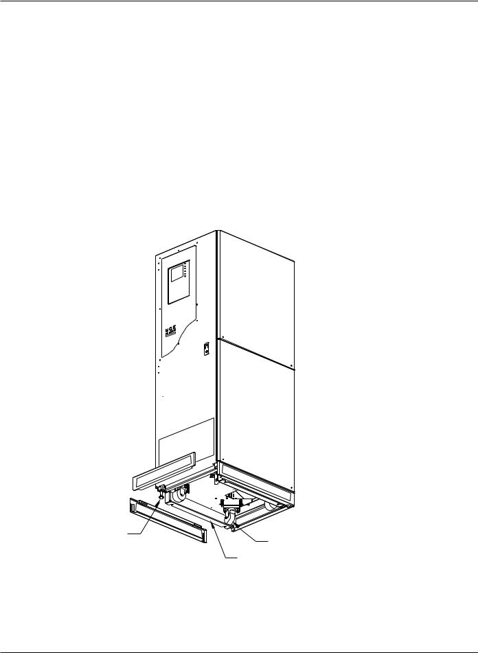
3.The casters on the unit will allow it to be positioned into the final installation location. At this point, the leveling legs can be adjusted to provide a level and stable footing for the Epsilon STS™ system.
Figure QS-1 Positioning of 200A Epsilon STS™.
LEVELING |
CASTERS |
|
JACKS |
||
|
OPTIONAL SEISMIC
BRACKETS
SECURED USING 3/8 BOLT
QS —2 |
Quick Start |
86-504004-00 B03 |
Installation and User Manual
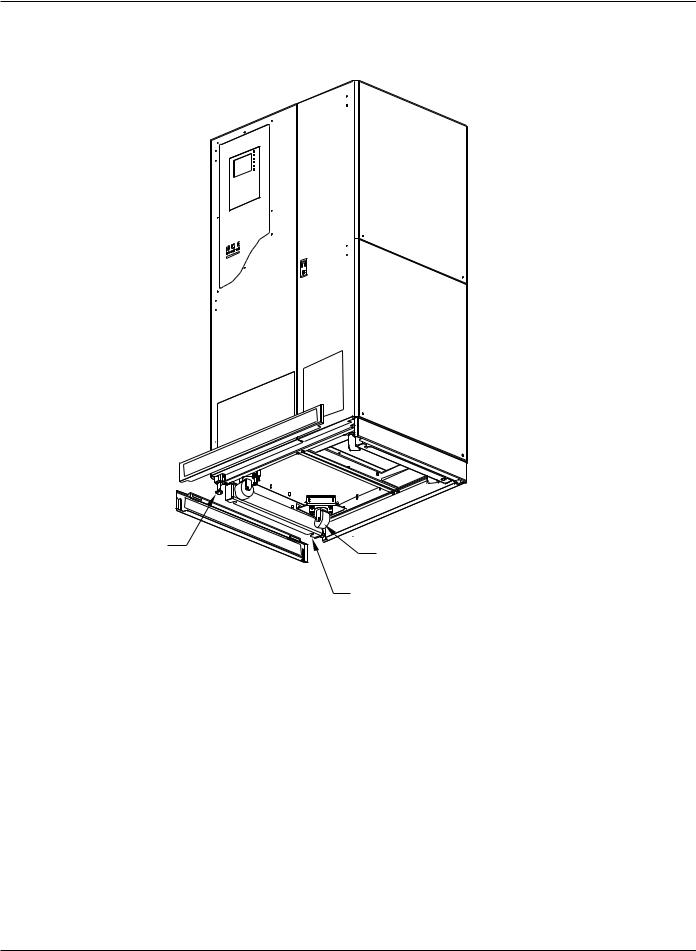
Figure QS-2 Positioning of 400/600A Epsilon STS™
LEVELING |
CASTERS |
|
JACKS |
||
|
OPTIONAL SEISMIC
BRACKETS
SECURED USING 3/8 BOLT
86-504004-00 B03 |
Quick Start |
QS —3 |
Epilson STSTM
Step 2 Connection of Utility Power Inputs
Connect Input Power from Two Sources
The Epsilon STS™ systems provides for either top or bottom cable entry. Connections are to be made with 75°C copper wire cables and using the lugs supplied with the STS unit. Refer to section 2.0 Installation and/or the system installation drawing(s) for more details (such as cable size and number of conductors).
NOTE: Three phase input power supplied as a Wye must have a separate, solidly grounded neutral that will be connected to the STS neutral busbar. If neutral is not supplied or not required for the load, connect only three phases and ground.
It is recommended to use isolation transformers so that the neutral of both AC sources can be grounded to the same potential.
Step 3 Connection of the Load Outputs
The Epsilon STS™ system provides for either top or bottom cable entry. Connections are to be made with 75°C copper wire cables and using the lugs supplied with the STS unit. Refer to section 2.0 Installation and/or the system installation drawing(s) for more details (such as cable size and number of conductors).
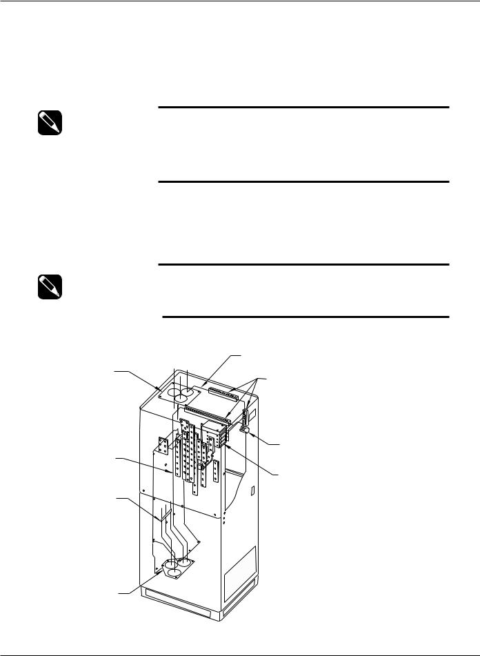
NOTE: Input and output cables inside the STS cabinet must be braced at 12” intervals as shown in Figures QS-3 and QS-4.
For Control Wiring connections refer to section 2.0 Installation.
Figure QS-3 200A STS Input/Output Power Connections.
CONTROL WIRES
THREADED THROUGH
PANDUIT/WIRE-WAYS
TOP ENTRY
CONDUIT PLATE CONTROL WIRE
PANDUIT/WIRE-WAYS
TB1
TERMINAL
CONTROL
WIRES
COMMUNICATION
CARDS
BRACE AT 12" INTERVALS
BOTTOM ENTRY
CONDUIT PLATE
QS —4 |
Quick start |
86-504004-00 B03 |
Installation and User Manual
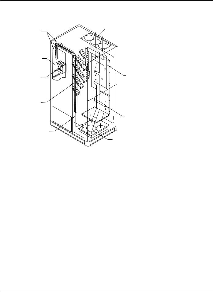
Figure QS-4 400/600A STS Input/Output Power Connections.
CONTROL WIRE
TOP ENTRY
PANDUIT/WIRE-WAYS
CONDUIT PLATE
COMMUNICATION |
|
|
CARDS |
|
|
TB1 |
CONTROL WIRES |
|
THREADED THROUGH |
||
TERMINAL |
||
UNIT |
||
|
CONTROL WIRE
PANDUIT/WIRE-WAYS
BRACE AT
12" INTERVALS
CONTROL WIRES
BOTTOM ENTRY
CONDUIT PAN
Step 4 Arrival of MGE Field Engineer
The MGE Field Engineer will finalize the initial Epsilon STS™ start-up. To insure a successful installation and reliable STS service, the MGE Field Engineer will verify all of the installation connections, fusing, and then will examine the extensive set of Epsilon STS™ personalization parameters to insure that the operation of the STS exactly matches your installation requirements.
86-504004-00 B03 |
Quick start |
QS —5 |

Epilson STSTM
Optional Steps
Should you require AC power on site prior to the arrival of the MGE Field Engineer, the following procedure will provide the AC power in the bypass mode. Should you have any questions about this procedure, do not hesitate to contact MGE Customer Support.
A.Ensure that all switches, CB1-5 in the STS are open (off).
B.Apply input power to the source S1 input of the STS by closing the upstream circuit breaker for source S1. The STS controls will power up and issues alarm(s). Silence the alarm buzzer by pressing the “Alarm Silence” pushbutton on the front display panel.
C.Lock CB5 (S2 bypass switch) and remove the lock key (for 4-interlock system, also lock CB2 and remove key). Using key(s), unlock and close CB4 (S1 bypass switch).
D.At this point, power will be available for site usage until the STS is properly commissioned.
E.Upon arrival of the MGE Field Service Engineer, the main power must be disconnected so that a safe and proper commissioning of the unit may be accomplished.
WARNING Do not, under any circumstance, close CB1, CB2, CB3A and
CB3B (if installed) until the unit has been commissioned by an
MGE Field Engineer.
Figure QS-5a 200A STS |
|
Figure QS-5b 400/600A STS |
|
STS MONITOR |
|
|
|
|
|
STS MONITOR |
|
|
|
CB1 |
|
|
|
CB4 |
|
CB1 |
CB4 CB3A |
|
|
CB2 |
CB5 CB3B |
|
KEY INTERLOCKS |
|
(2 - STANDARD |
||
|
|
CB2 |
|
|
|
4 - OPTIONAL) |
|
|
|
|
|
KEY INTERLOCKS |
|
CB5 |
|
(2 - STANDARD |
|
|
|
4 - OPTIONAL) |
|
|
|
|
|
CB3A |
|
|
|
CB3B |
|
QS —6 |
Quick start |
86-504004-00 B03 |

Introduction
1.0Scope
Introduction is a general description of system characteristics of Epsilon STSTM, its intended use and applicable electrical, mechanical and environmental specifications.
1.1Reference Manuals
160304-00 C00 JBUS/RS232, Installation and User manual.
1.2Section Descriptions
Quick Start
This Quick Start will guide qualified engineers through unpacking and positioning the unit, the equipment, tools, and steps required to perform power input/output connections to prepare the unit for MGE Field Service Engineers to perform on-site final installation and startup.
1 Introduction
Introduction is a general description of system characteristics of Epsilon STSTM, its intended use and applicable electrical, mechanical and environmental specifications.
2 Setup and Installation
Setup and Installation guides the User through tools and equipment required for making hardwire connections. Included are power cable connections with wire diagrams for configuring the product to specifications, and obtaining MGE field service assistance for final installation and startup.
3 Operation
Operation describes Epsilon STSTM system characteristics of indicators and controls, startup and shutdown procedures, safety checklists, modes and specifications and theory of operating the Epsilon STSTM system.
86-504004-00 B03 |
Introduction |
1 — 1 |
Epilson STSTM
1.3General Description
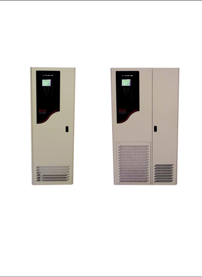
The Epsilon STS™ system is available in two different cabinet sizes. Dimensions for the cabinets are:
200A cabinet: 72”H x 24”W x 30”D
400A/600A cabinet: 72”H x 38”W x 30”D
Both cabinets are designed to provide for top and/or bottom entry of input and output power feeds.
The Epsilon STS™ system can be purchased to accept 208 VAC, 220 VAC, 240 VAC, 440 VAC, 480 VAC, 575 VAC or 600 VAC utility feed.
Figure 1-1a: Epsilon STS™ - 200A Cabinet. |
Figure 1-1b: Epsilon STS™ - 400/600A Cabinet. |
Physical Characteristics |
|
|
Enclosure Type |
NEMA 1, Free-standing, modular configured with hinged dead front construction |
|
|
protecting high voltage areas. |
|
Enclosure Dimensions Depth: |
30” (System will pass through standard 36” wide door). |
|
|
Height: |
72”. |
|
Width: |
24” for 200A STS; 38” for 400A and 600A STS. |
Accessibility |
Front access for operation and maintenance. Front or side access for customer power |
|
|
connection points. |
|
Power Connections/ |
All power connections and terminations to be solid copper braced rated for |
|
Busbars |
100KAIC.(400/600A models may be a combination of copper busbars and cables). |
|
Cable Entry |
Top and Bottom. |
|
Mounting |
360° Casters and Leveling Jacks with 1” minimum adjustment. |
|
1 — 2 |
Introduction |
86-504004-00 B03 |

Installation and User Manual
1.4Epsilon STSTM System Characteristics
The Epsilon digital Static Transfer Switch (STS) is a solid state, three-phase, break-before-make, dual position switch designed to connect a critical three-phase load to one of two separate, independent, synchronized sources of three-phase power. The STS consists of six pairs of SCR's connected in an AC switch configuration. Each 3- phase input is fed through a molded case automatic switch which provides short circuit protection by means of a magnetic trip only. The switch then feeds three pairs of “hockey-puck” SCR's, each pair consisting of two SCR's in an anti-parallel arrangement. The SCR outputs for each corresponding phase from both inputs are then connected and fed through an output isolation molded case switch to the output terminals. These SCR's are rated to carry the full 100% load (continuous rated) while operated as stipulated herein and at the maximum ambient temperature specified. The source to which the load is normally connected to is designated as the “Preferred” source, and the other redundant, standby source is the “Alternate” source. Selection of which input source is preferred is user selectable from the operator control panel, by control contact inputs, or through the communications port(s).
In normal operation, the load is connected to the preferred source as long as all phases of the preferred source are within the acceptable limits. Upon failure of the preferred source (more degraded than the alternate source), the load will be transferred to the alternate source until such time as the preferred source returns to within acceptable limits. The switching action itself is practically instantaneous and the time involved in the operation is mainly the sensing time required to determine that a transfer is necessary, normally a small fraction of a cycle.
The STS is controlled by a number of system operating variables which define the operation and performance of the system. Many of these variables may be adjusted for site-specific criteria.
The determination to transfer from one source to the other involves the evaluation of Source Qualities and System Operating parameters:
Source Quality |
Concerns the evaluation of a sources ability to support the critical load by evaluating |
|
the voltage, phase, current and frequency of a source on a real time basis. |
System Operating |
Parameters control transfers between the two sources, given the state of both |
|
sources and the load together with the specified site-specific operating criteria. |
During a transfer (or re-transfer), the SCR's of the loaded source are turned off and the SCR's of the previously unloaded source are turned on in such a way as to prevent any cross-current between sources, even if the sources have large phase displacement. Normally, transfer between sources with large phase difference is not allowed.
The molded case switches with magnetic trips will provide short circuit protection only – overcurrent protection must be provided by upstream and/or downstream devices.
Triple-redundant control power supplies, independent gate drive circuits for each sources SCR switch and other design features provide the optimal level of reliability and immunity to single point failures. The Epsilon STS™ is also built to withstand up to 100KA of available short circuit current.
A Bypassing scheme is provided. This can be used to manually bypass the AC load directly to either of the two power sources and isolate the static switching for servicing.
The Epsilon STS™ is available in three current ratings – 200A, 400A and 600A (208-600V range). The 200A model is natural convection cooled. The 400A and 600A models use forced air cooling by fans (with one redundant fan). The STS is designed for installation in a room where humidity and temperature can be controlled. The recommended and maximum environmental parameters are listed in Appendix B, of this document.
The Epsilon STS™ is listed for safety by Underwriters Laboratories, Inc. (UL) under UL Standard 1008.
86-504004-00 B03 |
Introduction |
1 — 3 |
Epilson STSTM
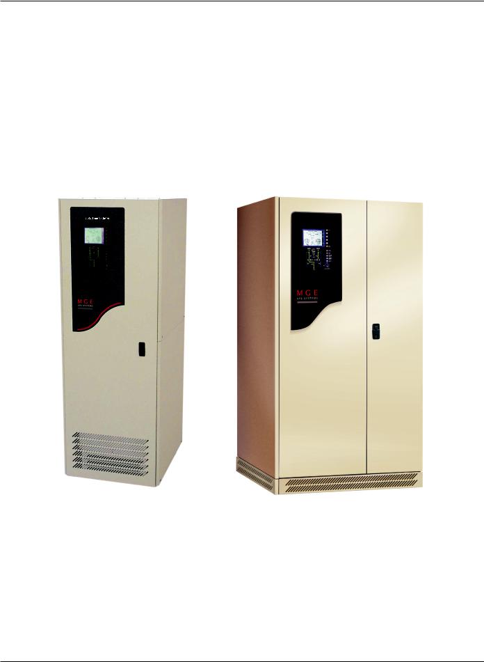
1.4.1PMM2 Plus and PMM2 Ultra
In the PMM2 Plus configuration, the input of the PMM2 cabinet is supplied by the output of the STS. The dual input distribution system accepts two independent AC input sources feeding to the STS. If the preferred input source power is not available, the STS will transfer to the alternate input source, avoiding interruption to the critical load. The output power is conditioned and stepped down to distribution voltage via an isolation transformer, feeding panelboards or main frame circuit beakers.
In the PMM2 Ultra configuration, an isolation transformer feeds each STS input source upstream of the STS. The transformer secondary output of the PMM2-1 (left cabinet) supplies the Source-1 input and PMM2-2 (right cabinet) supplies Source-2 input of the STS cabinet. If the preferred source input power is not available, the STS will transfer to the alternate input source, avoiding interruption to the critical load. The output of the STS connects to the output busbars of the PMM2-1 and PMM2-2 cabinets, feeding panelboards or main frame
Figure 1-2: PMM2 and PMM2 Ultra Cabinets.
1 — 4 |
Introduction |
86-504004-00 B03 |
 Loading...