


 Loading...
www.mgeups.com
Rackmount PDU
Installation
English
Français
Deutsch
Italiano
Español
R
R
E
T
N
I
N
U
E
H
T
U
P
T
I
B
|
|
O |
V |
I |
|
R |
|
||
|
|
|
||
P |
|
|
|
|
|
|
|
|
R
E
|
W |
P |
O |
|
L |
E |
|
D
E
R

www.mgeups.com
Rackmount PDU
Installation
R
R
E
T
N
I
N
U
E
H
T
U
P
T
I
B
|
|
O |
V |
I |
|
R |
|
||
|
|
|
||
P |
|
|
|
|
|
|
|
|
R
E
|
W |
P |
O |
|
L |
E |
|
D
E
R

Introduction
Thank you for selecting an MGE UPS SYSTEMS product to manage your electrical equipment.
The MGE Rackmount PDU range has been designed with the utmost care. We recommend that you take the time to read this manual to take full advantage of the many features of your PDU.
MGE UPS SYSTEMS pay great attention to the environmental impact of its products. Measures that have made the MGE Rackmount PDU a reference in environmental protection include:
Zthe eco-design approach used in product development,
Zrecycling of MGE Rackmount PDU
To discover the entire range of MGE UPS SYSTEMS products and the options available for the MGE Rackmount PDU range, we invite you to visit our website at www.mgeups.com or contact your MGE UPS SYSTEMS representative.
IMPORTANT: Before installing and using the MGE Rackmount PDU, always read the safety instructions (document number 301-0399-1).
Instructions
This symbol is intended to alert the user to the presence of important operating and maintenance (servicing) instructions in the literature accompanying the appliance.
Dangerous Voltage
This symbol is intended to alert the user to the presence of un-insulated dangerous voltage within the product’s enclosure that may be of sufficient magnitude to constitute a risk of electric shock to persons.
Protective Grounding Terminal
This symbol indicates a terminal that must be connected to earth ground prior to making any other connections to the equipment.

Getting Started
Quick Start Guide
The following instructions will help you quickly install and configure your PDU for use on your network. For detailed information on each step, go to the page number listed to the right.
For your network security, MGE UPS SYSTEMS strongly recommends the removal of the predefined user account prior to attachment to your network.
1. |
Mount the PDU ....................................................................................................................................... |
4 |
2. |
Connect to the power source.................................................................................................................. |
6 |
3. |
Connect the devices to the PDU ............................................................................................................ |
6 |
4. |
Connect to the PDU................................................................................................................................ |
6 |
5.Configure the PDU (Detailed instructions available in user manual)
•Login as the predefined Administrator (admn/admn)
•Create new administrative user account
•Configure location and tower names
•Configure outlet names
•Configure group names
•Configure new user account(s) with outlet and group access
•Remove the predefined Administrator
6.Connect the PDU to the network
Standard Accessories
Standard
•Mounting bracket hardware:
Vertical – two removable flanges with four M4 screws and two mounting L-brackets with two nut plates and four sets of screws and washers.
Horizontal/Rack – two mounting L-brackets and four screws.
•Outlet retention clips, one per outlet (208-240V units only).
•Separate power input cord(s) (non-hardwired units only).
•Power input retention bracket hardware (non-hardwired units only). Two removable T-brackets with two 40mm screws.
•Product Documentation CD-ROM.
•Safety and Installation Documentation.
Switched and remote monitoring Ampmeter PDUs
•RJ45 to RJ45 crossover cable.
•DB9F to DB25M modem cable.
•RJ45 to DB9F serial port adapter (for connection to standard DB9M DTE serial port).
Additional Required Items
•Phillip screwdriver
•Additional hardware to attach the unit to your rack
301-0399-2.doc - Page 3

Getting Started
Equipment Overview
The Input Current LED displays the current amperage load for the branch, phase or input. The power inlet connects to the electrical power source.
For Switched PDUs, a number is printed above each outlet.
4
Sensor |
1 |
Sensor |
2 |
1 Power Input |
3 |
|
2Input Current LED
3Ethernet / RS232 Ports
4 Temperature / Humidity Ports |
2 |
|
|
|
2 |
|
CInput |
|
urrent |
1
3
4
1
2
4
3
|
|
|
|
1 |
|
|
|
|
|
|
2 |
|
|
|
|
|
|
3 |
|
|
|
|
|
|
|
4 |
|
|
|
|
|
|
5 |
|
M |
|
G |
|
|
|
|
U P S |
|
|
E |
6 |
|
|
|
SY S |
T E |
|
|
||
w |
|
|
M S |
7 |
|
|
m ww.m |
geup |
|
|
|||
S m |
|
s.co |
|
In |
||
|
a r t |
8 |
Cuput |
|||
|
|
|
C |
D U |
rrent |
|
|
|
|
|
|
|
|
|
|
|
|
|
|
S |
|
|
|
|
|
|
ensor1 |
|
|
|
|
|
|
S |
|
|
|
|
I I I |
|
ensor2 |
|
|
|
|
Sens |
|
|
|
|
|
|
2 |
or |
|
|
|
|
|
|
1 |
|
|
A |
|
|
|
|
1 |
|
|
|
|
2 |
|
|
|
|
3 |
1 |
|
|
|
|
|
|
|
|
|
2 |
|
|
|
|
3 |
|
|
|
|
3 |
|
|
|
|
2 |
|
|
2 |
|
1 |
1 |
B |
|
|
|
|
2
2
1
Branch1
Branch2
M |
G |
|
|
|
|
U PS |
|
|
E |
||
|
|
SY |
ST E |
||
mwww.m |
geup |
|
M S |
||
A |
mpM |
s.co |
|||
|
eter |
||||
|
|
PDU |
|||
|
|
|
|
||
AUTION C
1
Figure 1: Unit Views
|
|
LNK |
|
|
|
Inp |
|
|
|
|
Cu |
ut |
|
|
|
|
rrent |
|
|
|
|
1 |
|
|
|
|
2 |
|
|
|
|
3 |
|
|
|
|
4 |
|
|
|
|
5 |
|
|
|
|
6 |
|
|
|
|
7 |
|
|
|
|
8 |
|
|
|
|
1-8 |
|
|
|
|
9 |
|
|
|
|
10 |
|
|
|
|
11 |
|
|
|
|
12 |
|
|
|
|
13 |
|
|
|
|
14 |
|
|
|
|
15 |
|
|
|
|
16 |
|
|
|
9-16 |
|
|
|
M |
G |
|
|
|
U PS |
|
E |
||
|
|
SY |
ST E |
|
mwww.m |
geup |
|
M S |
|
S |
|
|
|
|
|
witched |
s.co |
||
|
|
|
PDU |
|
UTION CA
Safety Precautions
IMPORTANT: Before installing and using the PDU, always read the safety instructions (document number 301-0399-1).
Page 4 - 301-0399-2 Rev A.
Getting Started
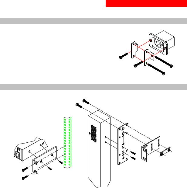
Installing the Power Input Retention Bracket
For PDUs with detachable input power cordsets, it may be necessary to install the power input retention bracket prior to mounting the PDU within the rack.
To install the power input retention bracket:
1.Remove the two screws attaching the IEC 60320 C19 inlet to the
enclosure.
2.Assemble and attach the retention bracket to the enclosure as
shown.
Figure 2: Retention Bracket assembly
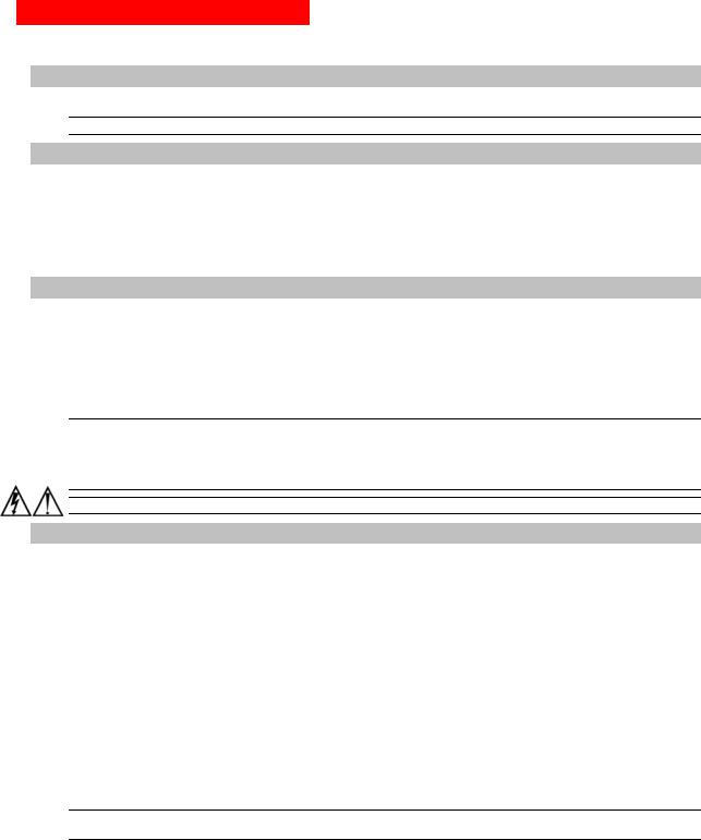
Mounting
Figure 3: Mounting
Horizontal/Rack
1.Select the appropriate bracket mounting points for proper mounting depth within the rack.
2.Attach the brackets to these mounting points with two screws for each bracket.
3.Install the enclosure into your rack, using the slots in each bracket. The slots allow about ¼ inch of horizontal adaptability to align with the mounting holes of your rack.
Vertical/Tower
1.Attach the removable flanges to the mount points on the rear of the enclosure using M4 screws.
2.Attach the mounting L-brackets to the flanges with the supplied screws, washers and nut plates. The slots allow about 1½ inches of vertical adaptability.
3.Attach the top and bottom brackets to your rack.
301-0399-2.doc - Page 5
Getting Started
Attaching the Redundant unit (Switched PDUs only)
Connect the Redundant Switched PDU with the provided RJ12 crossover cable at the Link port on the Switched PDU.
NOTE: The overall length of the cable should not exceed 10 feet.
Connecting to the Power Source
To attach a power cord (units with detachable cordsets only):
1.Plug the female end of the power cord firmly into its connector at the base.
2.Use a screwdriver to tighten the two screws on the retention bracket.
To connect to the power source:
Plug the male end of the power cord into the AC power source.
Connecting Devices
To avoid the possibility of noise due to arcing:
1.Keep the device’s on/off switch in the off position until after it is plugged into the outlet.
For Switched PDUs, log into the user interface and turn the outlets off before connecting the devices to the unit(s). After connecting the devices, turn them on from the user interface.
2.Connect devices to the outlets.
On 230V units, install a retention clip for each outlet; Pull the prongs out slightly and insert them into holes on the sides, then insert the device’s power cord and snap the clip over the cord.
NOTE:
1.MGE UPS SYSTEMS recommends even distribution of attached devices across the all available outlets to avoid exceeding any ratings limitations. See Power Ratings in the user manual more information.
2.The outlet retention clips provided with 230V units are designed for use with MGE UPS SYSTEMS’s IEC 60320/C13 to IEC 60320/C14 cable and may not properly fit 3rd party cables.
Always disconnect the power supply cords before opening to avoid electrical shock.
Connecting to the Unit
Serial (RS232) port
Switched PDUs and select Ampmeter PDU models are equipped with an RJ45 Serial RS-232 port for attachment to a PC or networked terminal server using the supplied RJ45 to RJ45 crossover cable and RJ45 to DB9F serial port adapter as required. See Data Connections in the user manual for more information on the Serial RS-232 port.
Ethernet port
Switched PDUs and select Ampmeter PDU models are equipped with an RJ45 10/100Base-T Ethernet port for attachment to an existing network. This connection allows access via Telnet, Secure Shell (SSH) or a common web browser.
The unit configured with the following network defaults to allow unit configuration out-of-the-box through either Telnet/SSH or via a web browser:
• |
IP address: |
192.168.1.254 |
• |
Subnet Mask: |
255.255.255.0 |
• |
Gateway: |
192.168.1.1 |
The local PC network connection must be configured as noted below:
NOTE: Contact your system administrator for instructions in reconfiguring the network connection. Reconfiguration of your network connection may require a restart to take effect.
• |
IP address: |
192.168.1.x (where x is 2-253) |
• |
Subnet Mask: |
255.255.255.0 |
Page 6 - 301-0399-2 Rev A.

www.mgeups.com
Rackmount PDU
Installation
R
R
E
T
N
I
N
U
E
H
T
U
P
T
I
B
|
|
O |
V |
I |
|
R |
|
||
|
|
|
||
P |
|
|
|
|
|
|
|
|
R
E
|
W |
P |
O |
|
L |
E |
|
D
E
R

Introduction
Merci d'avoir sélectionné un produit MGE UPS SYSTEMS pour gérer votre équipement électrique.
La gamme de MGE Rackmount PDU a été conçue avec les plus grands soins. Nous vous recommandons de lire attentivement ce manuel afin de profiter pleinement des nombreuses fonctions de votre PDU.
MGE UPS SYSTEMS se pr.occupe de l'impact de ses produits sur l'environnement. Les ressources mises en oeuvre font de MGE Rackmount PDU une référence en matière de protection de l'environnement don’t en particulier :
Zune démarche déco-conception pendant son cycle de développement,
Zle recyclage de MGE Rackmount PDU en fin de vie du produit.
Pour découvrir tous les produits MGE UPS SYSTEMS ainsi que les options disponibles pour la gamme de MGE Rackmount PDU, nous vous invitons à consulter notre site Web à l'adresse suivante www.mgeups.com ou à contacter directement votre représentant MGE UPS SYSTEMS.
IMPORTANT : lisez toujours les instructions relatives à la sécurité (référence 301-0399-1) avant d'installer et d'utiliser votre MGE Rackmount PDU.
Instructions
Ce symbole indique les instructions importantes relatives au fonctionnement et à l'entretien (réparation) contenues dans la documentation de cet appareil.
Tension dangereuse
Ce symbole indique la présence de tension dangereuse non isolée dans l'enveloppe de protection électrique de cet appareil. L'intensité de cette tension est telle qu'elle constitue un risque d'électrocution pour tous.
Borne de masse protectrice
Ce symbole indique qu'il faut mettre à la masse toute borne auquel il se rapporte avant d'effectuer toute autre connexion sur l'appareil.
Démarrage
Guide de démarrage rapide
Les instructions suivantes vous permettront d'installer et de configurer rapidement votre PDU sur votre réseau. Vous obtiendrez des informations détaillées pour chaque étape en vous reportant au numéro de page correspondant (à droite).
Pour des raisons de sécurité, MGE UPS SYSTEMS vous recommande fermement de supprimer le compte utilisateur prédéfini avant de connecter cet appareil sur votre réseau.
1. |
Montage du PDU .................................................................................................................................... |
4 |
2. |
Connexion à la source d'alimentation..................................................................................................... |
6 |
3. |
Connexion des périphériques au PDU ................................................................................................... |
6 |
4. |
Connexion au PDU................................................................................................................................. |
6 |
5.Configuration du PDU (voir instructions détaillées dans le manuel de l'utilisateur)
•Connexion en tant qu'administrateur prédéfini (admn/admn)
•Création d'un nouveau compte utilisateur administratif
•Configuration des noms de tours et d'emplacements
•Configuration des noms de sorties
•Configuration des noms de groupes
•Configuration des nouveaux comptes utilisateur avec sortie et accès de groupe
•Suppression d'un administrateur prédéfini
6.Connexion du PDU au réseau
Accessoires standard
Standard
•Matériel de support de fixation :
Vertical – deux brides amovibles accompagnées de quatre vis M4 ; deux supports de fixation en L amovibles accompagnés de deux plateaux-écrous ; quatre jeux de vis et de rondelles.
Horizontal/Rack – deux supports de fixation en L accompagnés de quatre vis.
•Clips de rétention de sortie, une par sortie (uniquement pour les unités de 208-240 V).
•Cordon(s) d'alimentation entrante séparé(s) (uniquement pour les unités sans circuit en fil métallique).
•Matériel de support de rétention pour l'alimentation entrante (uniquement pour les unités sans circuit en fil métallique).
Deux supports de fixation en T amovibles accompagnés de deux vis de 40 mm.
•CD-ROM de documentation produit.
•Documentation d'installation et de sécurité.
Switched PDU et Ampmeter PDU son contrôle distant
•Câble croisé RJ45 à RJ45.
•Câble modem DB9F à DB25M.
•Adaptateur de port série RJ45 à DB9F (pour connexion au port série DTE standard DB9M).
Également requis
•Tournevis Phillip
•Matériel supplémentaire pour fixer l'unité au rack
301-0399-2 Rev A. - Page 3
Loading...