


Pulsar EX 700
51031604EN/AA - Page 1
Installation and
user manual
Pulsar EX
700 / 1000 / 1500
e-mail: info@direktronik.se
tel: 08-52 400 700 fax: 08-520 18121

Page 2 - 51031604EN/AA
Introduction
Thank you for selecting an MGE UPS SYSTEMS product to protect your electrical equipment.
The Pulsar EX range has been designed with the utmost care. We recommend that you take the time to read this manual
to take full advantage of the many features of your UPS.
MGE UPS SYSTEMS pays great attention to the environmental impact of its products. Measures that have made Pulsar
EX a reference in environmental protection include:
◗ the eco-design approach used in product development;
◗ recycling of Pulsar EX at the end of its service life.
To discover the entire range of MGE UPS SYSTEMS products and the options available for the Pulsar EX range, we invite
you to visit our web site at www.mgeups.com or contact your MGE UPS SYSTEMS representative.

51031604EN/AA - Page 3
Safety
Safety of persons
Safety rules
A UPS has its own internal power source (the battery). Consequently, the power outlets may be energised even if the UPS
is disconnected from the AC-power source.
Dangerous voltage levels are present within the UPS. It should be opened exclusively by qualified service
personnel.
The UPS must be properly earthed. Measurements are required to ensure that the total leakage current of the UPS
and the protected equipment does not exceed 3.5 mA.
The battery supplied with the UPS contains small amounts of toxic materials. To avoid accidents, the directives
listed below must be observed:
◗ Never burn the battery (risk of explosion).
◗ Do not attempt to open the battery (the electrolyte is dangerous for the eyes and skin).
◗ Comply with all applicable regulations for the disposal of the battery.
◗ Batteries constitute a danger (electrical shock, burns). The short-circuit current may be very high. Precautions
must be taken for all handling.
Product safety
UPSs must be connected to a nearby wall outlet that is easily accessible.
The UPS can be disconnected from the AC-power source by removing the power cord.
◗ Never install the UPS near liquids or in an excessively damp environment.
◗ Never let a foreign body penetrate inside the UPS.
◗ Never block the ventilation grates of the UPS.
◗ Never expose the UPS to direct sunlight or a source of heat.
Special precautions
The UPS connection instructions contained in this manual must be followed in the indicated order.
Check that the indications on the rating plate correspond to your AC-power system and to the actual electrical consumption
of all the equipment to be connected to the UPS.
If the UPS must be stored prior to installation, storage must be in a dry place.
The admissible storage temperature range is -20° C to +45° C.
If the UPS remains de-energised for a long period, we recommend that you energise the UPS for a period of 24 hours, at
least once every month. This charges the battery, thus avoiding possible irreversible damage.
Prior to handling the battery:
◗ remove all watches, rings, bracelets and any other metal objects;
◗ use tools with insulated handles.
Page 4 - 51031604EN/AA
Foreword
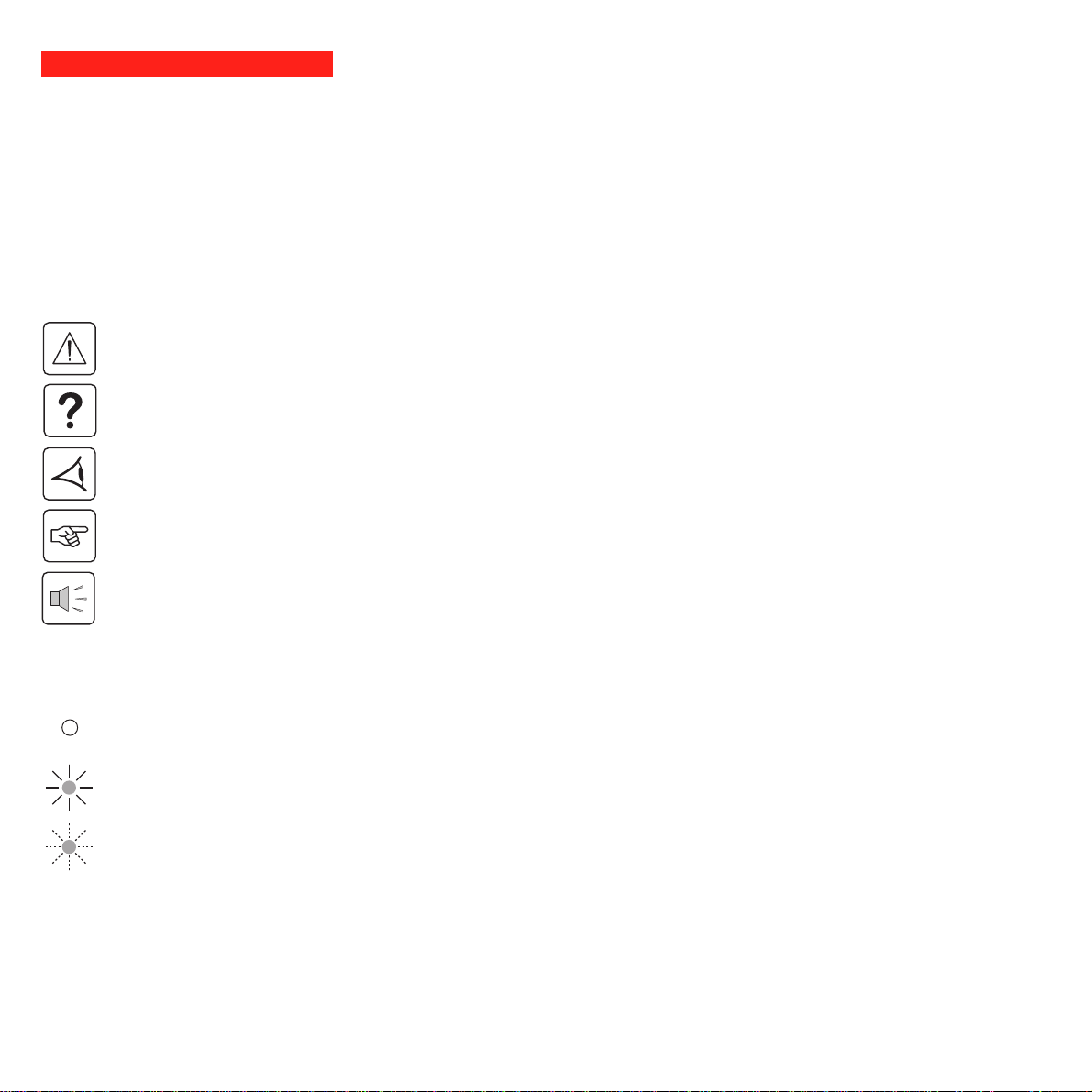
Using this document
Important instructions that must always be followed.
Information, advice, help.
Visual indication.
Action.
Audio indication.
In the illustrations on the following pages, the symbols below are used:
LED off.
LED on.
LED flashing.
Information may be found primarily by consulting:
◗ the contents,
◗ the index.
Pictograms

51031604EN/AA - Page 5
Contents
1. Presentation
1.1 Pulsar EX range .......................................................................................................................... 7
Tower model.................................................................................................................................... 7
Rack model ..................................................................................................................................... 7
1.2 Back ............................................................................................................................................. 8
Tower model.................................................................................................................................... 8
Rack model ..................................................................................................................................... 9
1.3 Control panel ............................................................................................................................... 10
2. Installation
2.1 Unpacking and checks ............................................................................................................... 11
Tower model.................................................................................................................................. 11
Rack model ................................................................................................................................... 12
2.2 Installation of the rack version .................................................................................................. 13
2.3 Connection to the RS 232 or USB communications port (optional)........................................ 14
2.4 Installation of the communications-card option ...................................................................... 15
Tower model.................................................................................................................................. 15
Rack model ................................................................................................................................... 15
2.5 Connections ................................................................................................................................ 16
Tower model.................................................................................................................................. 16
Rack model ................................................................................................................................... 16
3. Operation
3.1 Start-up ........................................................................................................................................ 17
3.2 Bargraph indications .................................................................................................................. 17
3.3 Operation on battery power (following failure of AC input power) ............................................. 18
Transfer to battery power .............................................................................................................. 18
Threshold for the low-battery warning...........................................................................................18
End of backup time ....................................................................................................................... 18
Sleep mode ................................................................................................................................... 18

Page 6 - 51031604EN/AA
Contents
3.4 Personalisation (optional) ........................................................................................................... 19
Function ........................................................................................................................................ 19
"ON / OFF conditions" tab............................................................................................................. 19
"Battery" tab .................................................................................................................................. 19
"Output" tab ................................................................................................................................... 20
"Bypass" tab .................................................................................................................................. 20
3.5 Shutdown..................................................................................................................................... 20
4. Maintenance
4.1 Troubleshooting.......................................................................................................................... 21
4.2 Replacement of the battery module .......................................................................................... 22
Tower model.................................................................................................................................. 22
Rack model ................................................................................................................................... 23
5. Environment ............................................................................................................. 24
6. Appendices
6.1 Technical characteristics ........................................................................................................... 25
Simplified diagram ........................................................................................................................ 25
Operating conditions ..................................................................................................................... 25
6.2 Glossary....................................................................................................................................... 26
6.3 Index............................................................................................................................................. 27
51031604EN/AA - Page 7
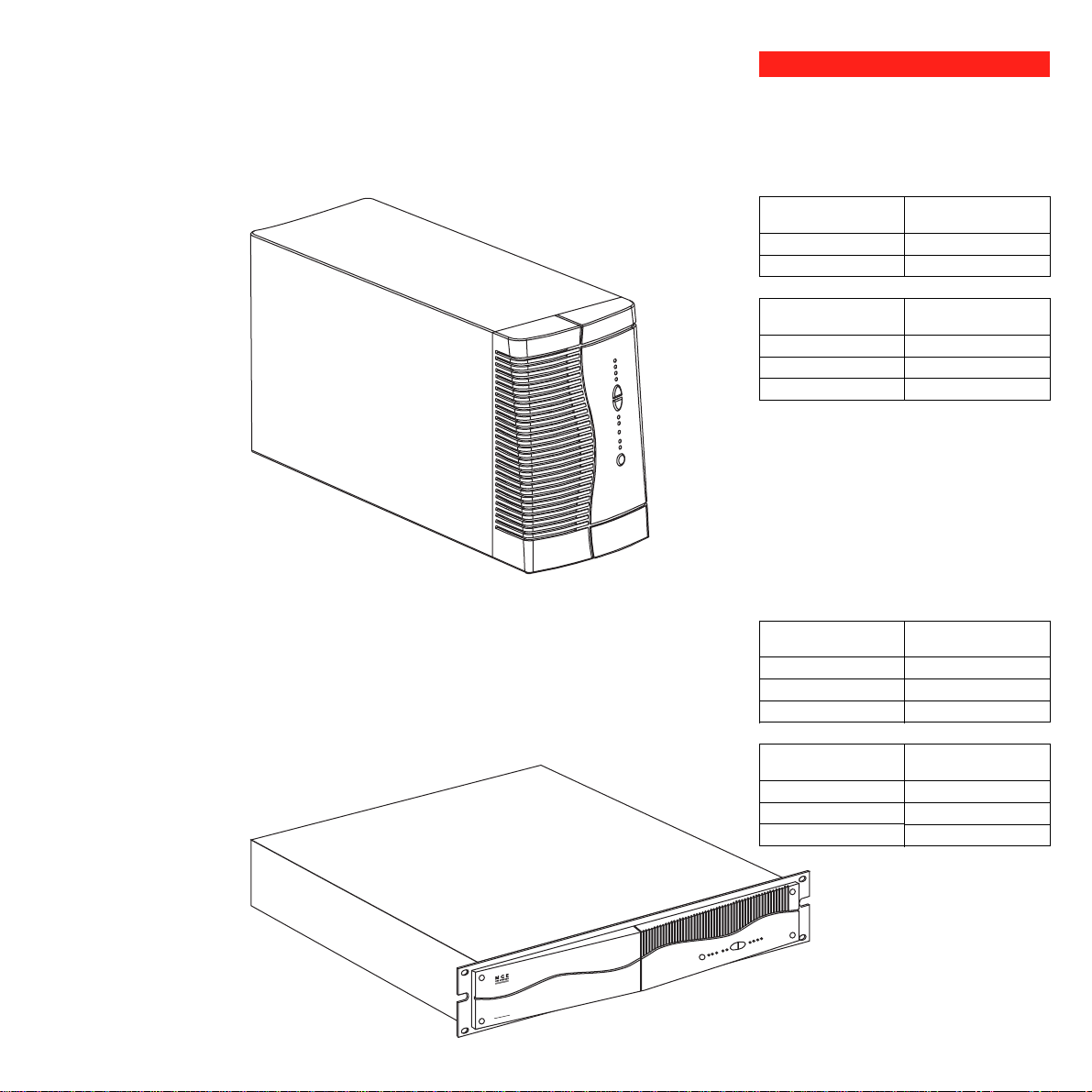
1. Presentation
1.1 Pulsar EX range
Tower model
Rack model
EX 700 / EX 1000
EX 1500
EX 700
EX 1000
EX 1500
Dimensions in mm
(H x W x D)
235.5 x 145 x 400
235.5 x 145 x 505
Weight in kg
10
12
15
EX 700 Rack
EX 1000 Rack
EX 1500 Rack
EX 700 Rack
EX 1000 Rack
EX 1500 Rack
Dimensions in mm
(H x W x D)
88 (2U) x 482.6 x 430
88 (2U) x 482.6 x 430
88 (2U) x 482.6 x 493
Weight in kg
14
16
20
EX1000 Rack
Page 8 - 51031604EN/AA
1
2
RS232
USB
1
2
RS232
USB
5
1. Presentation
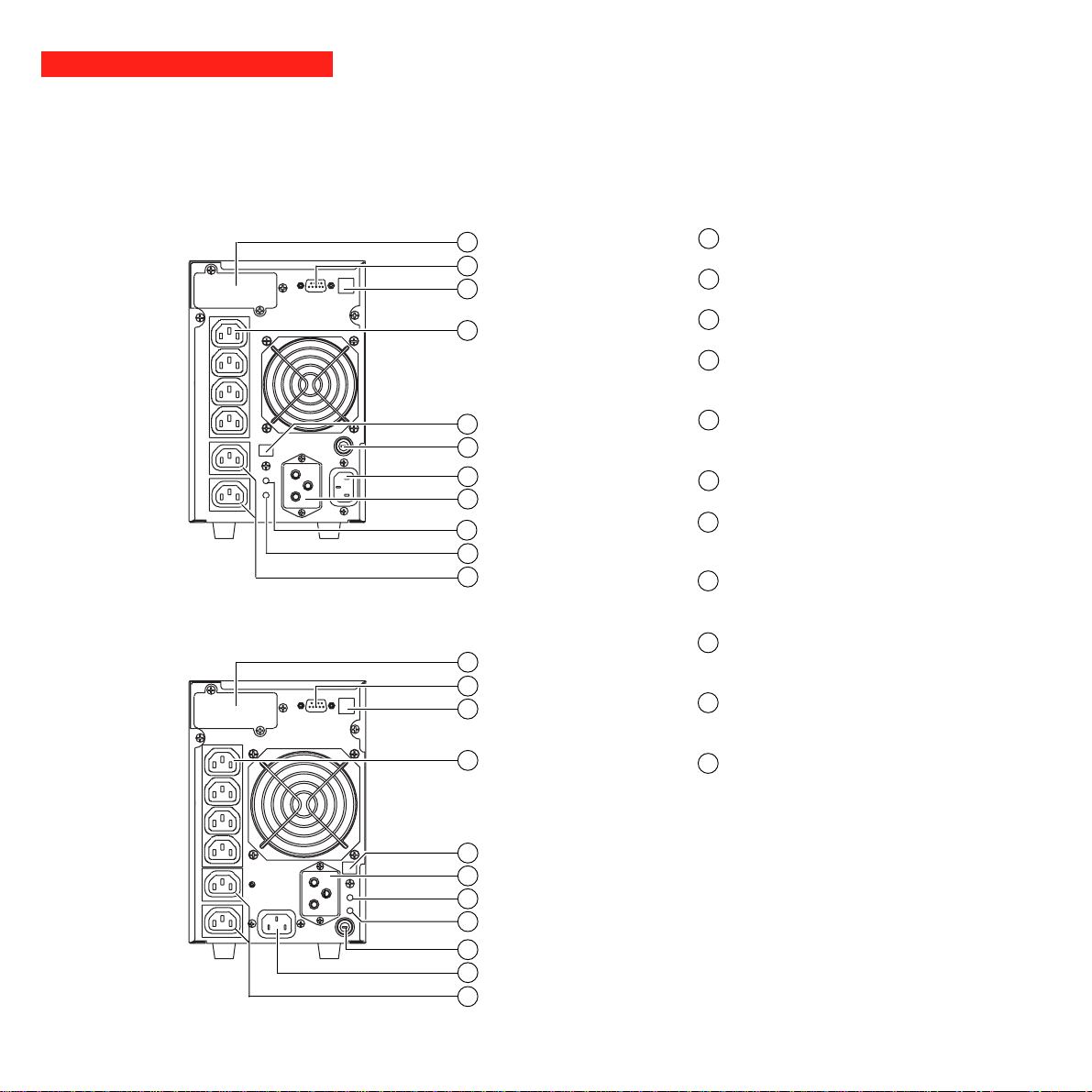
1.2 Back
Pulsar EX 1500
Pulsar EX 700 / Pulsar EX 1000
slot for communications-card option.
RS232 communications port.
USB communications port.
four outlets for direct connection of
protected equipment.
connector for automatic detection of an
additional battery module.
input circuit breaker.
socket for connection to AC-power
source.
connector for an additional battery
module.
pushbutton to test phase/neutral
inversion of AC-power source.
LED indicating phase/neutral inversion
of AC-power source.
two programmable outlets (outlet 1 and
2).
1
2
3
4
5
6
7
9
8
10
11
6
7
8
11
1
5
2
3
10
4
9
1
2
3
10
4
8
9
Tower model
6
7
11
51031604EN/AA - Page 9
1
2
RS232
USB
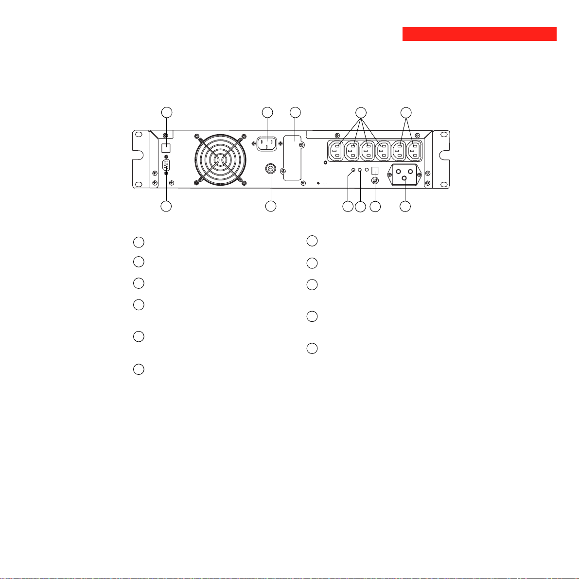
1. Presentation
Pulsar EX 700 Rack / Pulsar EX 1000 Rack / Pulsar EX 1500 Rack
7
6
1
4 11
8
3
9
10
Rack model
slot for communications-card option.
RS232 communications port.
USB communications port.
four outlets for direct connection of
protected equipment.
connector for automatic detection of an
additional battery module.
input circuit breaker.
1
2
3
4
5
6
7
9
8
10
11
socket for connection to AC-power source.
connector for an additional battery module.
pushbutton to test phase/neutral inversion of
AC-power source.
LED indicating phase/neutral inversion of
AC-power source.
two programmable outlets (outlet 1 and 2).
2
5
 Loading...