


POWER-SURE 700
Three Phase
Power Conditioners
Installation and User Manual
www.mgeups.com
Power-
Sure
™

IMPORTANT SAFETY INSTRUCTIONS
SAVE THESE INSTRUCTIONS – This manual contains important instructions for Power-Sure™ 700 that must be
followed during operation of the equipment.
WARNING Opening enclosures expose hazardous voltages. Always refer service to
qualified personnel only.
ATTENTION L'ouverture des cabinets expose des tensions dangereuses. Assurez-vous
toujours que le service ne soit fait que par des personnes qualifiees.
WARNUNG! Das öffnen der Gehäuse legen gefährliche Spannungen bloss. Service
sollte immer nur von qualifizierten Personal durchgeführt werden.
WARNING As standards, specifications, and designs are subject to change, please
ask for confirmation of the information given in this publication.
ATTENTION Comme les normes, spécifications et produits peuvent changer, veuillez
demander confirmation des informations contenues dans cette publication.
WARNUNG! Normen, Spezifizierungen und Pläne unterliegen Anderungen. Bitte verlan-
gen Sie eine Bestätigung über alle Informationen, die in dieser Ausgabe
gemacht wurden.
NOTE This equipment has been tested and found to comply with the limits for a
Class A digital device, pursuant to part 15 of the FCC rules. These limits
are designed to provide reasonable protection against harmful interference
when the equipment is operated in a commercial environment.
This equipment generates, uses, and can radiate radio frequency energy
and, if not installed and used in accordance with the instruction manual,
may cause harmful interference to radio communications. Operation of this
equipment in a residential area is likely to cause harmful interference in
which case the user will be required to correct the interference at user's
own expense.
Certification Standards
◗ ANSI/IEEE C57.12.91 Standards
◗ IEEE C62.41 cat.A3
◗ NFPA 70 – National Electrical Code
◗ FCC rules and regulations of Part 15, Subpart J, Class A
◗ UL listed under 1012, Power Supplies - General Purpose
◗ NEMA PE 1 (National Electrical Manufacturers Association)
◗ NEMA 250 (National Electrical Manufacturers Association)
– Enclosures for Electrical Equipment (1000 Volts Maximum)
◗ ISO 9001
◗ Occupational Safety & Health Administration (OSHA)
Important Safety information
Power-Sure™ 700 —
Three Phase Power Conditioners
ii
86-108814-00 B01

86-108814-00 B01
WARNING To reduce the risk of fire or electric shock, install in a temperature and
humidity controlled indoor area free of conductive contaminants.
This equipment is intended only for installations in a RESTRICTED
ACCESS LOCATION.
ATTENTION Pour réduire le riske d'inccendie ou d'électrocution, installer dans une
enciente intérieure contrôlée en température et humidité et sans
contaminants conducteurs.
Ce matériel est destiné seulement pour des installations dans un
EMPLACEMENT RESTREINT d'cAccès.
WARNUNG! Um die Gefahr von Feuer und elektrischem Schock zu reduzieren, muss
das Gerät in einem temperatur – und feuchtigkeitskontrollierten Raum, frei
von leitungsfähigen Verunreinigungen, installiert werden. Dieses Gerät ist
nur für die Installation an einem Ort mit eingeschränkter Zugangserlaubnis
vorgesehen.
Diese Ausrüstung ist nur für Anlagen in einem EINGESCHRäNKTEN
ZUGRIFF STANDORT bestimmti.
WARNING HIGH LEAKAGE CURRENT. Earth connection essential before connecting
supply.
ATTENTION COURANT DE FUITE ELEVE. Raccordement a la terre indispensable avant le
raccordement au reseau.
WARNUNG! Hoher Ableitstrom Vor Inbetriebnahme Schutzleiterverbindung herstellen.
How to use this manual and Symbol Usage
This manual is designed for ease of use and easy location of information.
Locate specific topics in the Table of Contents.
Typographical conventions use single quote marks in procedures to denote a prompt for user action:
For example:
1. After the selections are complete, click on the “Save” button.
This manual uses four icon symbols with text to convey important information and tips.
WARNING indicates information provided to protect the user and service personnel against
safety hazards and/or possible equipment damage.
CAUTION indicates information provided to protect the user and service personnel against
possible equipment damage.
IMPORTANT indicates information provided as an operating instruction, or as an operating tip.
NOTE indicates information provided as an operating tip or an equipment feature.
How To Use This Manual
iii
Installation and User Manual

86-108814-00 B01
Power-Sure™ 700 —
Three Phase Power Conditioners
iv
CAUTION: Record All Serial Numbers
CAUTION: Record All Serial Numbers!
RECORD ALL SERIAL NUMBERS FOR THE POWER-SURE™ 700 AND COMPONENTS.
THESE SERIAL NUMBERS WILL BE REQUIRED IF YOUR SYSTEM NEEDS SERVICE.
KEEP THIS MANUAL IN A PLACE WHERE YOU CAN REFERENCE THE SERIAL
NUMBERS IF SERVICE IS REQUIRED!
POWER-SURE™ 700 SERIAL NUMBER: _______________________________________________
ADDITIONAL SERIAL NUMBERS:
____________________________ ______________________________
____________________________ ______________________________
____________________________ ______________________________
____________________________ ______________________________
____________________________ ______________________________
____________________________ ______________________________
____________________________ ______________________________
____________________________ ______________________________
____________________________ ______________________________
____________________________ ______________________________

v
Installation and User Manual
86-108814-00 B01
Power-Sure™ 700
Three Phase
Power Conditioners
Installation and User Manual
Revision History
Power-Sure™ 700 Three Phase Power Conditioners
Installation and User Manual
86-108814-00
Revision: A00 Initial Release 09/2003
A01 ECN#: 003787 02/2004
B00 ECN#: 004681 08/2006
B01 ECN#: 005088 12/2006
For service call
1-800-523-0142
Copyright © 2006 MGE UPS SYSTEMS, INC.
All rights reserved. Printed in U.S.A.
MGE UPS SYSTEMS, INC.
1660 Scenic Avenue
Costa Mesa, CA 92626
(714) 557-1636

(This page left blank intentionally)
Power-Sure™ 700 —
Three Phase Power Conditioners
vi 86-108814-00 B01

86-108814-00 B01
c i
Installation and User Manual
Contents
section description . . . . . . . . . . . . . . . . . . . . . . . . . . . . . . . . . . . . . . . . . . .page
IMPORTANT SAFETY INSTRUCTIONS . . . . . . . . . . . . . . . . . . . . . . .ii
Certification Standards . . . . . . . . . . . . . . . . . . . . . . . . . . . . . . . . . . . . .ii
How to Use This Manual and Symbol Usage . . . . . . . . . . . . . . . . . . .iii
CAUTION: Record All Serial Numbers! . . . . . . . . . . . . . . . . . . . . . . . .iv
Revision History . . . . . . . . . . . . . . . . . . . . . . . . . . . . . . . . . . . . . . . . . .v
Section 1 Introduction
section description . . . . . . . . . . . . . . . . . . . . . . . . . . . . . . . . . . . . . . . . . . .page
1.0 Scope . . . . . . . . . . . . . . . . . . . . . . . . . . . . . . . . . . . . . . . . . . . . . .1 — 1
1.1 Reference Manuals . . . . . . . . . . . . . . . . . . . . . . . . . . . . . . . . . . .1 — 1
1.2 Section Descriptions . . . . . . . . . . . . . . . . . . . . . . . . . . . . . . . . . . .1 — 1
1.3 Receiving and Inspection Notes . . . . . . . . . . . . . . . . . . . . . . . . . .1 — 2
1.3.1 Location and Storage . . . . . . . . . . . . . . . . . . . . . . . . . . . . . . . . . .1 — 2
1.4 General Description . . . . . . . . . . . . . . . . . . . . . . . . . . . . . . . . . . .1 — 2
1.4.1 Electrical and Performance Specifications . . . . . . . . . . . . . . . . . 1 — 3
1.4.2 Main Transformer Specification . . . . . . . . . . . . . . . . . . . . . . . . . .1 — 3
1.4.3 Input Breaker . . . . . . . . . . . . . . . . . . . . . . . . . . . . . . . . . . . . . . . .1 — 4
1.5 Monitoring the Power-Sure™ 700 . . . . . . . . . . . . . . . . . . . . . . . .1 — 4
1.6 Protection for the Power-Sure™ 700 . . . . . . . . . . . . . . . . . . . . . .1 — 4
Section 2 Installation and Operation
section description . . . . . . . . . . . . . . . . . . . . . . . . . . . . . . . . . . . . . . . . . . .page
2.0 Scope . . . . . . . . . . . . . . . . . . . . . . . . . . . . . . . . . . . . . . . . . . . . . .2 — 1
2.1 Installation Notes . . . . . . . . . . . . . . . . . . . . . . . . . . . . . . . . . . . . .2 — 1
2.2 MGE UPS Systems Power-Sure™ 700 . . . . . . . . . . . . . . . . . . . .2 — 1
2.3 Power-Sure™ 700 Installation Drawings and
Cabinet Dimensions . . . . . . . . . . . . . . . . . . . . . . . . . . . . . . . . . . .2 — 2
2.4 General Operation Notes . . . . . . . . . . . . . . . . . . . . . . . . . . . . . . .2 — 5
2.5 Power-Sure™ 700 Cable Connections . . . . . . . . . . . . . . . . . . . .2 — 6
2.5.1 Input Wire Size, Grounding and Output Wiring . . . . . . . . . . . . . .2 — 6
2.6 Start-up Sequence . . . . . . . . . . . . . . . . . . . . . . . . . . . . . . . . . . . .2 — 8
Contents

Section 3 Maintenance
section description . . . . . . . . . . . . . . . . . . . . . . . . . . . . . . . . . . . . . . . . . . .page
3.0 Scope . . . . . . . . . . . . . . . . . . . . . . . . . . . . . . . . . . . . . . . . . . . . . .3 — 1
3.1 Preventive Maintenance . . . . . . . . . . . . . . . . . . . . . . . . . . . . . . . .3 — 1
Power-Sure™ 700 Performance Checklist . . . . . . . . . . . . . . . . . .3 — 2
3.2 Troubleshooting Guide . . . . . . . . . . . . . . . . . . . . . . . . . . . . . . . . 3 — 4
3.3 Troubleshooting Power Line and Electrical Connections . . . . . . .3 — 5
3.3.1 Step 1. Disassembling the Power Conditioners . . . . . . . . . . . . . .3 — 5
3.3.2 Step 2. Electrical Connections, Fuses . . . . . . . . . . . . . . . . . . . . .3 — 5
3.4 Checking the Power Modules (SCR) . . . . . . . . . . . . . . . . . . . . . .3 — 5
3.5 Check SCR Snubber Card . . . . . . . . . . . . . . . . . . . . . . . . . . . . . .3 — 6
3.5.1 Check Control Card and Filter Card . . . . . . . . . . . . . . . . . . . . . . .3 — 7
3.6 Final Testing and Adjustments . . . . . . . . . . . . . . . . . . . . . . . . . . .3 — 8
3.7 Unit Component Location Diagrams . . . . . . . . . . . . . . . . . . . . . .3 — 9
3.8 SCR Heat Sink Assemblies . . . . . . . . . . . . . . . . . . . . . . . . . . . .3 — 12
3.9 Field Adjustments of Circuit Cards . . . . . . . . . . . . . . . . . . . . . . .3 — 15
3.9.1 Power-Sure™ 700 Control Card #49120/407415 . . . . . . . . . . .3 — 15
3.9.2 Control Card Adjustment Procedure . . . . . . . . . . . . . . . . . . . . . .3 — 16
3.9.3 Over/Under Voltage Detection Board #35867 . . . . . . . . . . . . . .3 — 17
3.9.3.1 Undervoltage Adjustment . . . . . . . . . . . . . . . . . . . . . . .3 — 17
3.9.3.2 Overvoltage Adjustment . . . . . . . . . . . . . . . . . . . . . . . .3 — 17
3.9.3.3 Delay Adjustment . . . . . . . . . . . . . . . . . . . . . . . . . . . . .3 — 18
3.10 Manual Bypass Switch Option . . . . . . . . . . . . . . . . . . . . . . . . . .3 — 18
3.10.1 Normal Mode . . . . . . . . . . . . . . . . . . . . . . . . . . . . . . . . . . . . . . .3 — 18
3.10.2 Bypass Mode . . . . . . . . . . . . . . . . . . . . . . . . . . . . . . . . . . . . . . .3 — 18
3.10.3 Remote Emergency Power OFF (REPO) (Optional) . . . . . . . . .3 — 18
3.11 Replacement Parts . . . . . . . . . . . . . . . . . . . . . . . . . . . . . . . . . .3 — 19
3.12 Parts Numbers . . . . . . . . . . . . . . . . . . . . . . . . . . . . . . . . . . . . . .3 — 19
Appendices
Appendix A
A-1: 10-50kVA Wiring Diagram . . . . . . . . . . . . . . . . . . . . . . . . . . . . . .A — 1
A-2: 75-150kVA Wiring Diagram . . . . . . . . . . . . . . . . . . . . . . . . . . . . .A — 2
A-3: 125-300kVA Wiring Diagram . . . . . . . . . . . . . . . . . . . . . . . . . . . .A — 3
MGE Warranty & Propriety Rights . . . . . . . . . . . . . . . . . . . . . . . . . . . . . . . . . . . . . . . .W — 1
MGE Warranty
Proprietary Rights Statement
Technical Support and Field Service . . . . . . . . . . . . . . . . . . . . . . . . . . . . . . . . . . . . . .W — 3
MGE Service and Repair
Who to Contact
Scheduling Field Service Engineer Support
Return for Repair (RMA)
Contents
Power-Sure™ 700 —
Three Phase Power Conditioners
c ii
86-108814-00 B01

Contents
c iii
Installation and User Manual
Figures
figure description . . . . . . . . . . . . . . . . . . . . . . . . . . . . . . . . . . . . . . . . . . . . . . . . .page
2-1: Power-Sure™ 700 — 10-15kVA Mechanical Cabinet Measurements . . .2 — 2
2-2: Power-Sure™ 700 — 25-30kVA Mechanical Cabinet Measurements . . .2 — 3
2-3: Power-Sure™ 700 — 45-150kVA Mechanical Cabinet Measurements . .2 — 4
2-4: Power-Sure™ 700 — 225-300kVA Mechanical Cabinet Measurements .2 — 5
3-1: Power Module . . . . . . . . . . . . . . . . . . . . . . . . . . . . . . . . . . . . . . . . . . . . .3 — 5
3-2: Test Wire Diagram . . . . . . . . . . . . . . . . . . . . . . . . . . . . . . . . . . . . . . . . . .3 — 6
3-3: Power-Sure™ 700 — 10-15kVA Major Components . . . . . . . . . . . . . . . .3 — 9
3-4: Power-Sure™ 700 — 25-30kVA Major Components (Rear View) . . . . . .3 — 9
3-5: Power-Sure™ 700 — 45-150kVA Major Components (Rear View) . . . .3 — 10
3-6: Power-Sure™ 700 — 225-300kVA Cable Connections,
Input Output Locations. . . . . . . . . . . . . . . . . . . . . . . . . . . . . . . . . . . . . .3 — 11
3-7: Power-Sure™ 700 — 10-30kVA SCR Heatsink Assembly . . . . . . . . . .3 — 12
3-8: Power-Sure™ 700 — 45-50kVA SCR Heatsink Assembly . . . . . . . . . .3 — 13
3-9: Power-Sure™ 700 — 75-150kVA SCR Heatsink Assembly . . . . . . . . .3 — 14
3-10: Power-Sure™ 700 — 225-300kVA SCR Heatsink Assembly . . . . . . . .3 — 15
3-11: Power-Sure™ 700 Controller Card (Top View) . . . . . . . . . . . . . . . . . . .3 — 16
Tables
table description . . . . . . . . . . . . . . . . . . . . . . . . . . . . . . . . . . . . . . . . . . . . . . . . .page
2-1: 480 VAC Input and 208 VAC Output Wire Size Chart . . . . . . . . . . . . . . .2 — 7
2-2: 208 VAC Input and 208 VAC Output Wire Size Chart . . . . . . . . . . . . . . .2 — 7
3-1: Power-Sure™ 700 Power Conditioners Part Numbers . . . . . . . . . . . . .3 — 19
86-108814-00 B01

(This page left blank intentionally)
Power-Sure™ 700 —
Three Phase Power Conditioners
c iv 86-108814-00 B01

1.0 Scope
This section is a general description of the Power-Sure™ 700 Three Phase Power Conditioners. Includes receiving,
location and storage, electrical, mechanical specifications, monitoring, and internal protection for components.
1.1 Reference Manuals
N/A
1.2 Section Descriptions
This manual is divided into three sections:
Section 1: Introduction
This section is a general description of the Power-Sure™ 700 Three Phase Power Conditioners. It includes receiving,
location and storage, electrical and mechanical specifications, monitoring and internal protection for components.
Section 2: Installation and Operation
This section describes installation requirements, system dimensions, cable connections, and start-up procedures
for the Power-Sure™ 700 Three Phase Power Conditioners.
Section 3: Maintenance
This section contains preventive maintenance for the Power-Sure™ 700, electrical connection troubleshooting,
checking power modules (SCR), voltage adjustments, and PCB card troubleshooting to assist the user with commu-
nication and configuration connections.
Installation and User Manual
Introduction
Introduction
1 — 1
86-108814-00 B01

1.3 Receiving and Inspection Notes
Before accepting the shipment from the freight carrier, inspect the exterior surfaces of all shipping containers or
packaging used, and the equipment, for damage that may have occurred during transit. If the shipping containers
or equipment shows evidence of damage, note the damage on the receiving document (bill of lading) prior to signing
for receipt of equipment.
ALL CLAIMS FOR SHIPPING DAMAGE MUST BE FILED DIRECTLY WITH THE CARRIER. Replacements for
damaged components should be ordered through MGE UPS SYSTEMS.
Check by thorough inspection if any electrical connections have become loose because of vibration during
shipment. Remove top and side panels (Not applicable on 225kVA and larger).
Check the nameplate to be sure that the voltage and frequency match the available power supply. Under no circum-
stance should the unit be connected to a power source which does not conform to the nameplate rating.
1.3.1 Location and Storage
The unit has been completely inspected and extensively tested under various load conditions prior to shipment.
Care to install it at a proper location will assure long trouble free operation. The unit is forced air cooled with the air
intake at the bottom, front or sides and exhausts out at the top or rear. Therefore, it should be installed in a clean,
dry place with enough clearance to allow a free flow of air.
Allow at least 4 inches of space between the unit and the wall or other equipment for portable units.
Allow enough space for maintenance as indicated on the cabinet outlines. See Section 2.0, Figures 2-1 thru 2-4. If
the equipment is to be stored prior to installation, it should be stored in a cool, dry, well-ventilated location that is
protected from rain, splashing water, chemical agents, etc. The equipment should be covered with a tarpaulin or
plastic wrapper to protect it against dust, dirt, paint, or other foreign materials.
1.4 General Description
The Power-Sure™ 700 is a continuous duty power conditioner designed to supply reliable, clean regulated power to
critical loads. An efficient design with state of the art micro-processor controlled solid state devices provide immunity
to all line disturbances. The cabinet is a heavy gauge industrial steel throughout. Metal is anti-corrosive phosphate
treated prior to paint. Paint is a baked finish.
The basic design consists of a three phase triple shielded isolation transformer with seven separate voltage taps
per phase. Output regulation is achieved by monitoring the input and automatically switching taps anytime the input
line sags or surges. The use of a triple shielded isolation transformer provides superior common mode and trans-
verse mode noise attenuation. Automatic switching occurs during current zero allowing noise free switches for both
leading and lagging power factor loads that are connected to the Power-Sure™ 700.
The Power-Sure™ 700 Power Conditioner is operated by simply turning on the main AC input circuit breaker. As an
option, units may have a bypass switch. This is a no load switch and MUST only be operated when the unit is OFF.
The bypass switch should be in the “NORMAL” position unless a problem occurs with the system. If a problem
occurs, turn OFF the main AC circuit breaker and turn the bypass switch to the “BYPASS” position. Re-energize the
system by turning on the AC circuit breaker and contact the Customer Care Center for repairs.
Any ‘ALERT” condition requires the main AC input breaker to be turned off in order to reset the “ALERT” light.
Introduction - Description
Power-Sure™ 700 —
Three Phase Power Conditioners
1 — 2
86-108814-00 B01

Introduction - Specifications
1 — 3
Installation and User Manual
1.4.1 Electrical and Performance Specifications
*Output Maintained to within ± 3% of nominal.
*Input +10% to -20% of the nominal rated input.
*Frequency 60 Hertz ± 3 Hertz.
Efficiency 95% Minimum.
Line Regulation Output is ± 3% of nominal for input variations of +10% to -20% of nominal.
Load Regulation Output maintained within 3% from no load to full load.
Response Time 1/2 Cycle.
Correction Time Output will correct in one step to within ±3% of nominal in 1.5 cycles or less.
Harmonic Distortion Adds less than 1.0% THD.
Transverse-Mode 3 dB down at 1000 Hertz, 40 dB decade to below 50 dB with resistive load.
Noise Attenuation
Common-Mode 120 dB or greater.
Noise Attenuation
Audible Noise 45 dB to 55 dB, depending on kVA rating.
Turn On Characteristics When energized voltage overshoot will be less than 5% of nominal for 1 cycle
or less.
Overload Rating 1000% for 1 cycle and 200% for 10 seconds.
Ambient Rating -10 to +40 degrees Celsius.
*Optional extended input regulation range provided on some units. If provided, reference description next to the
units specification tag. 50 Hz models available.
Listed to UL1012, Standard for “power units other than Class 2”.
1.4.2 Main Transformer Specification
Windings All copper.
Magnetics Grain orientated, M6 grade, stress relieved transformer steel is utilized for
minimum losses and maximum efficiency.
Insulation Class (N) 200 all sizes.
Shielding Multiple triple copper shield to minimize interwinding capacitance, transient,
and noise coupling between primary and secondary windings.
Cooling Convection, operating temp is 130 degrees Celsius maximum rise
above ambient.
Isolation Output is fully isolated from input.
86-108814-00 B01

1.4.3 Input Breaker
Main input molded case circuit breaker, rated at 125% of full load input current.
1.5 Monitoring the Power-Sure™ 700
Monitoring of the Power-Sure™ 700 is simple, clean, and effective. Three green light indicators are utilized to
display “POWER ON” (output line to neutral for each phase) and one red light indicator to display “ALERT”. The
“POWER ON” display is connected directly to the output that indicates the Power-Sure™ 700 is operating properly
with just a quick glance. The “ALERT” display represents an overtemp problem or output voltage loss (optional)
when illuminated, and will shut down the output, but cooling fans remain on. Overtemp thermal sensors are strate-
gically located at critical points on the regulator assemblies and transformer. The main AC input circuit breaker must
be turned off in order to reset the “ALERT” light.
1.6 Protection for the Power-Sure™ 700
Protection is accomplished very effectively to minimize failures and the cost of repairs by the four major methods
listed below:
1. The input is protected with a integrally mounted AC circuit breaker for abnormal current overloads and provides
a convenient means of disconnecting utility power.
As an option, the input breaker may be equipped with a shunt trip device that is interfaced with a REMOTE
EMERGENCY POWER OFF PUSH BUTTON. By pressing this button, the input breaker will trip and
disable the Power-Sure™ 700 completely. The input breaker must be physically reset before unit will
turn on again.
2. The electronic regulating devices are protected with fast acting semi-conductor fuses. These fuses are
designed to clear before damage occurs to the more expensive SCR regulating devices. The main transformer
is protected by fuse links connecting the SCR regulators together, and are designed to clear in the event that
two or more SCRs should fail. This will prevent a transformer tap short and the possibility of transformer failure.
3. When provided with the optional Under/Over Voltage Shutdown Card (UOV2020), the output of the
Power-Sure™ 700 is constantly monitored for extreme over and under voltage conditions. This card monitors
each output phase and will electronically disable the Power-Sure™ 700 when any phase exceeds +10% or
-10% of nominal output voltage.
4. Overtemp sensing devices are mounted at critical points on the SCR regulating assembly and the main trans-
former. When an overtemp condition exists the “ALERT” light will illuminate and hold until the overtemp is
corrected. There are no automatic shutoff circuits for the “ALERT” condition. The main AC input breaker must
be turned off in order to reset the “ALERT” light.
Introduction - Protection
Power-Sure™ 700 —
Three Phase Power Conditioners
1 — 4
86-108814-00 B01

2.0 Scope
This section describes installation requirements, system dimensions, cable connections, and start-up procedures
for the Power-Sure™ 700 Three Phase Power Conditioners.
WARNING: HIGH VOLTAGE, ONLY QUALIFIED ELECTRICIANS SHOULD INSTALL OR
PERFORM MAINTENANCE.
2.1 Installation Notes
◗ The Power-Sure™ 700 requires ventilation. Reference Section 1.3.1 for cabinet placement for each model.
◗ After installation is complete, verify the output voltage is within its rated specifications.
◗ Provide overcurrent protection per article NFPA 70 latest revision article 450-3(b).
◗ Optional output cables must be specified in lengths of 10 feet, cables may have receptacles on the termi-
nating end.
◗ For installation of conduit, reference NEC Article 348 and 350 and any applicable local electrical codes.
Refer to the following installation diagrams for electrical hookup.
2.2 MGE UPS Systems Power-Sure™ 700
An efficient installation depends on careful planning and site preparation. Installation of the equipment must be
handled by skilled technicians and electricians familiar with the special requirements of high-voltage electrical
equipment. The installation must comply with the requirements of the National Electrical Code (ANSI/NFPA 70,
latest issue) and local codes as applicable, and safety standard, UL1012 listed; UL1449 compliant; meets FCC Cat. A.
We strongly recommend contacting MGE for system start-up. Do not allow unqualified personnel to handle, install,
or operate the Power-Sure™ 700.
A good way to insure that the Power-Sure™ 700 is sized properly is to use the following guide lines:
◗ List each piece of equipment, include Model, Voltage, Current and kVA.
◗ Calculate kVA of load plus a safety margin.
◗ When this is not possible, gather the data by reading the specification plate of the equipment you plan on
backing up.
◗ One method is to ask the vendor of the computer equipment to supply you with the information you need.
◗ Be sure to verify the input supply voltage and the output requirements of the Power-Sure™ 700.
Installation and User Manual
Installation and Operation
Installation and Operation
2 — 1
86-108814-00 B01
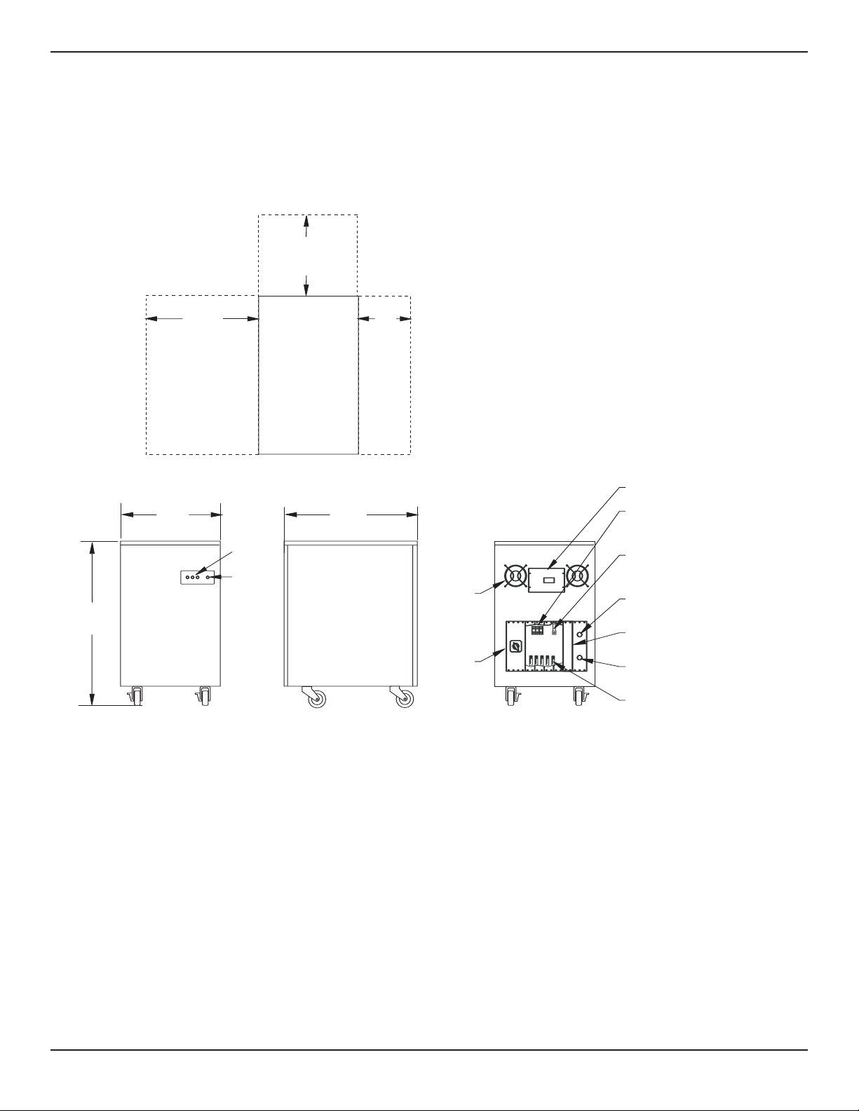
2.3 Power-Sure™ 700 Installation Drawings and Cabinet Dimensions
When sizing the Power-Sure™ 700, be sure to take into consideration all loads and circuits the Power-Sure™ 700 is
to supply.
Figure 2-1: Power-Sure™ 700 — 10-15kVA Mechanical Cabinet Measurements.
24"
(609.60m)
CLEARANCE FOR
SERVICEABILITY
30"
(762m)
21.5"
(546.10m)
“ON”
LIGHTS
“ALERT”
LIGHTS
FRONT VIEW RIGHT SIDE VIEW
29"
(736.60m)
TOP VIEW
12"
(304.80m)
FOR INSTALLATION
PURPOSES ONLY
12"
(304.80m)
FOR INSTALLATION
PURPOSES ONLY
ENVIRONMENTAL
CLEARNESS
TO REMOVE TOP: REMOVE RETAINING SCREW
IN REAR OF TOP, LIFT REAR
AND SLIDE FORWARD
TO REMOVE SIDE: REMOVE RETAINING SCREW
IN TOP OF PANEL, LIFT PANEL
STRAIGHT UP
A
OUTPUT
BC
CONDITIONED POWER
ALERT
G
N
L3
L2
L1
H3
H2
H1
INPUT TERMINALS
ALLEN BRADLEY #1492-CE2
#12-I/O WIRE
REAR VIEW
COOLING
FANS
OPTIONAL
BYPASS
OUTPUT TERMINALS CONSISTS OF
PK9 GROUNDING BAR
WIRE: 14 ga. - 4 ga. &
ta 2/0 lug
WIRE: 14 ga - 2/0
INPUT BREAKER
INPUT GROUND TERMINAL
ILSCO #TA-2
#2-#14 WIRE
OUTPUT DISTRIBUTION
(OPTIONAL)
HOLE PROVIDED FOR
1 INPUT CONDUIT
HOLE PROVIDED
1 OUTPUT CONDUIT
Installation and Operation
Power-Sure™ 700 —
Three Phase Power Conditioners
2 — 2
86-108814-00 B01
 Loading...