


Galaxy PW
Galaxy PW™
100 to 225 kVA
User’s Manual
www.mgeups.com


Galaxy PW™
User ’s Manual
For service call
1-800-438-7373
86-133060-00 X1 08/02
Copyright © 2002 MGE UPS Systems, Inc..
All rights reserved. Printed in U.S.A.
MGE UPS Systems
1660 Scenic Avenue
Costa Mesa, CA 92626
(714) 557-1636
www.mgeups.com
800/523-0142

ii Chapter name
Galaxy PW 100 to 225 kVA User’s Manual
This page intentionally left blank

iiiImportant Safety Instructions
IMPORTANT SAFETY INSTRUCTIONS
SAVE THESE INSTRUCTIONS — This manual contains important instructions for EPS 6000
inverters that must be followed during installation, operation and maintenance of the equipment.
WARNING
Opening enclosures expose hazardous voltages. Always refer service to qualified personnel only.
ATTENTION
L'ouverture des cabinets expose des tensions dangereuses. Assurez-vous toujours que le service ne
soit fait que par des personnes qualifiees.
WARNUNG!
Offene Raeume entladen gefaehrliche Stromspannungen. Bitte wenden sie sich an qualifiziertes Dienstpersonal.
WARNING
To reduce the risk of fire or electric shock, install in a temperature and humidity controlled indoor area
free of conductive contaminants.
ATTENTION
Pour réduire le riske d'inccendie ou d'électrocution, installer dans une enciente intérieure contrôlée en
température et humidité et sans contaminants conducteurs.
WARNUNG!
Um die Gefahr von Feuer und elektrischem Schock zu reduzieren, muss das Geraet in einem temperatur und feuchtigkeitskontrolliertem Raum, frei von leitungsfaehigen Verunreinigungen, installiert werden.
WARNING
As standards, specifications, and designs are subject to change, please ask for confirmation of the
information given in this publication.
ATTENTION
Comme les normes, spécifications et produits peuvent changer, veuillez demander confirmation
des informations contenues dans cette publication.
WARNUNG!
Normen, Spezifizierungen und Plaene unterliegen Aenderungen. Bitte beantragen Sie schriftliche
Bestaetigung ueber Informationen die in dieser Herausgabe gemacht wurden.
NOTE
This equipment generates, uses, and can radiate radio frequency energy and, if not
installed and used in accordance with the instruction manual, may cause harmful
interference to radio communications. Operation of this equipment in a residential area
is likely to cause harmful interference in which case the user will be required to correct
the interference at his own expense.

This page intentionally left blank
iv

vWarranty
Galaxy PW™
User ’s Manual
Warranty
Seller warrants to the Ultimate Purchaser (the purchaser who buys for use, and not for resale) that all products furnished under this order and which are manufactured by Seller will conform to final specifications, drawings, samples and other written descriptions approved in writing by Seller, and will be free from defects in
materials and workmanship. These warranties shall remain in effect for period of twelve (12) months after delivery to the Ultimate Purchaser. But if the Seller installs
the equipment or supplies technical direction of installation by contract, said one year shall run from the completion of installation, provided installation is not unreasonably delayed by Ultimate Purchaser. Parts replaced or repaired in the warrant period shall carry the unexpired portion of the original warranty. Aunit placed with
the Purchaser on consignment and then later purchased will be warranted for twelve (12) months from the time the Seller receives notification of the Purchaser’s
intent to purchase said consigned item. The foregoing in its entirety is subject to the provision that in no case will the total warranty period extend beyond 18 months
from date Seller ships equipment from point of manufacture.
The liability of Seller hereunder is limited to replacing or repairing at Seller’s factory or on the job site at Seller’s option, any part or parts which have been returned to
the Seller and which are defective or do not conform to such specifications, drawings or other written descriptions; provided that such part or parts are returned by
the Ultimate Purchaser within ninety (90) days after such defect is discovered. The Seller shall have the sole right to determine if the parts are to be repaired at the
job site or whether they are to be returned to the factory for repair or replacement. All items returned to Seller for repair or replacement must be sent freight prepaid
to its factory. Purchaser must obtain Seller’s Return Goods Authorization prior to returning items. The above conditions must be met if warranty is to be valid. Seller
will not be liable for any damage done by unauthorized repair work, unauthorized replacement parts, from any misapplication of the item, or for damage due to accident, abuse, or Act of God.
In no event shall the Seller be liable for loss, damage, or expense directly or indirectly arising from the use of the units, or from any other cause, except as expressly
stated in this warranty. Seller makes no warranties, express or implied, including any warranty as to merchantability or fitness for a particular purpose or use. Seller is
not liable for and Purchaser waives any right of action it has or may have against Seller for any consequential or special damages arising out of any breach of warranty, and for any damages Purchaser may claim for damage to any property or injury or death to any person arising out of its purchase of the use, operation or
maintenance of the product. Seller will not be liable for any labor subcontracted or performed by Purchaser for preparation of warranted item for return to Seller’s factory or for preparation work for field repair or replacement. Invoicing of Seller for labor either performed or subcontracted by Purchaser will not be considered as a liability by the Seller.
This warranty shall be exclusive of any and all other warranties express or implied and may be modified only by a writing signed by an officer of the Seller. This warranty shall extend to the Ultimate Purchaser but to no one else. Accessories supplied by Seller, but manufactured by others, carry any warranty the manufacturers
have made to Seller and which can be passed on to Ultimate Purchaser.
Seller makes no warranty with respect to whether the products sold hereunder infringe any patent, U.S. or foreign, and Buyer represents that any specially ordered
products do not infringe any patent. Buyer agrees to indemnify and hold Seller harmless from any liability by virtue of any patent claims where Buyer has ordered a
product conforming to Buyer’s specifications, or conforming to Buyer’s specific design.
Buyer has not relied and shall not rely on any oral representation regarding the Product sold hereunder and any oral representation shall not bind Seller and shall not
be part of any warranty.
There are no warranties which extend beyond the description on the face hereof. In no event shall MGE UPS SYSTEMS, Inc. be responsible for consequential damages or for any damages except as expressly stated herein.
Service and Factory Repair - Call 1 - 800 - 438 - 7373
Direct questions about the operation, repair, or servicing of this equipment to MGE UPS SYSTEMS, Inc. Customer Support Services. Include the part number,
assembly number, and serial number of the unit in any correspondence. Should you require factory service for your equipment, contact MGE UPS SYSTEMS, Inc.
Customer Support Services and obtain a Return Goods Authorization (RGA) prior to shipping your unit. Never ship equipment to MGE UPS SYSTEMS, Inc. without
first obtaining an RGA.
Proprietary Rights Statement
The information in this manual is the property of MGE UPS SYSTEMS, Inc., and represents a proprietary article in which MGE UPS SYSTEMS, Inc., retains any and
all patent rights, including exclusive rights of use and/or manufacture and/or sale. Possession of this information does not convey any permission to reproduce, print,
or manufacture the article or articles shown herein. Such permission may be granted only by specific written authorization, signed by an officer of MGE UPS SYSTEMS, Inc.
IBM, PC-AT, ES/9000, and AS/400 are trademarks of International Business Machines Corporation. MGE and MGE UPS SYSTEMS are trademarks of MGE UPS
SYSTEMS, Inc. Other trademarks that may be used herein are owned by their respective companies and are referred to in an editorial fashion only.
Revision History
Galaxy PW™ User's Manual
86-133060-00
Copyright © 2002 MGE UPS SYSTEMS. All rights reserved. Printed in U.S.A.
Revision: X1 08/02
Galaxy PWTM100 to 225 kVA user’s manual

This page intentionally left blank
vi

1Contents
contents
safety instructions ......................................................................................................iii
warranty .....................................................................................................................v
how to use this manual .............................................................................................2
introduction
general characteristics of Galaxy PW™ UPS ..........................................................3
system description ..................................................................................................4
different types of Galaxy PW™ systems ..................................................................5
isolation and protection devices ..............................................................................5
operation in on-line mode ........................................................................................6
inverter shutdown or overload ..................................................................................8
operation with an engine generator set......................................................................9
output voltage quality and continuity ........................................................................9
description of Galaxy PW™ cabinets
UPS ........................................................................................................................10
battery ......................................................................................................................10
control panel
general ....................................................................................................................11
indications ................................................................................................................11
start-up
system start-up ........................................................................................................13
start-up of a module ..............................................................................................13
shutdown
shutdown of the inverter ..........................................................................................14
shutdown of a rectifier/charger ..............................................................................14
control-panel display
general organization ................................................................................................15
display of messages ................................................................................................15
measurement system ..............................................................................................19
voltage measurements ............................................................................................19
current measurements ............................................................................................19
power and frequency measurements ....................................................................19
battery measurements ..........................................................................................20
selections and settings ..........................................................................................20
alarms
general ....................................................................................................................22
maintenance bypass ..............................................................................................22
environment information
signal reception ......................................................................................................23
signal transmission ................................................................................................23
logging and time-stamping
presentation of event time-stamping by Galaxy PW™............................................24
utilization via the Galaxy PW™ display ..................................................................24
utilization via Teleservice ........................................................................................27
maintenance
maintenance configuration........................................................................................28
battery maintenance ................................................................................................30
visual check..............................................................................................................30
functional check ......................................................................................................30
options
galvanic and voltage matching transformers
maintenance bypass ................................................................................................31
electrical supervision ..............................................................................................31
2 How to Use this Manual
This manual is designed for ease of use and easy location of information.
To quickly find the meaning of terms used within the text, look in the Glossary.
This manual uses Noteboxes to convey important information. Noteboxes come in four varieties:
A WARNING notebox
indicates information
provided to protect the
user and service
personnel against safety
hazards and/or possible
equipment damage
WARNING
A CAUTION notebox
indicates information
provided to protect the
user and service
personnel against
possible equipment
damage.
CAUTION
An IMPORTANT notebox
indicates information
provided as an operating
instruction, or as an
operating tip.
IMPORTANT
A NOTE notebox
indicates information
provided as an
operating tip or an
equipment feature.
NOTE
All products in the Galaxy PW™ range are protected by patents. They implement original technology not available to competitors of MGE UPS SYSTEMS.
To take into account evolving standards and technology, equipment may be modified
without notice. Indications concerning technical characteristics and dimensions are not
binding unless confirmed by MGE UPS SYSTEMS.
This document may be copied only with the written consent of MGE UPS SYSTEMS.
Galaxy PWTM100 to 225 kVA
how to use this manual
3
introduction
Introduction
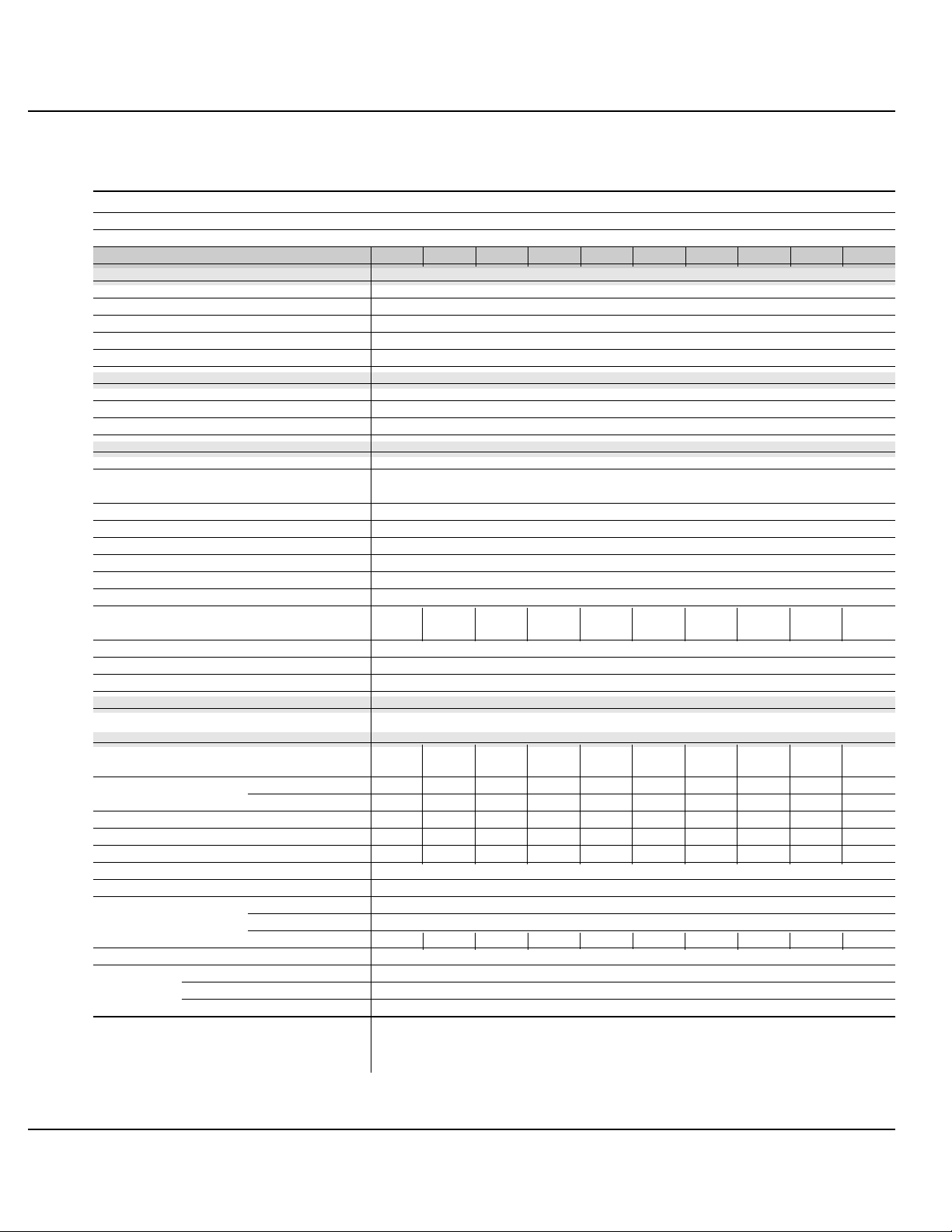
general characteristics of Galaxy PW™ UPS
UPS power rating in kVA 100 130 150 180 200 225
Normal AC input
number of conductors 3 phases
rated voltage and tolerances 480 V ± 10% (adjustable to ± 15%)
rated frequency and tolerances 60 Hz / ± 10%
THDI < 14% < 11% < 10% < 8% < 7.6% < 7.5%
power factor up to 0,9
Bypass AC input
number of conductors 3 phases 3 phases + neutral
rated voltage and tolerances 480 V / ± 10%
rated frequency and tolerances 60 Hz / ± 10%
Load
number of conductors 3 phases 3 phases + neutral
Ph/Ph voltages 480 V
Ph/N voltages 277 V
voltage fluctuations ± 1%
adjustable frequency and tolerances
(on battery power) 60 Hz ± 0,05 Hz
synchronization with bypass ± 0.5 Hz (adjustable from ± 0.25 Hz to ± 2 Hz)
voltage variation for 0 to 100% load step change ± 2% (with battery)
permissible overloads 150% for 1 minute, 125% for 10 minutes
Isc Ph/Ph (% of I rated) 4.7 3.6 3.2 2.6 2.4 2.1
Isc Ph/N (% of I rated) 7.4 5.7 5 4.1 3.7 3.3
THDU Ph/Ph and Ph/N for linear load < 1,5% Ph/Ph, < 2% Ph/N
THDU Ph/Ph and Ph/N for non-linear load < 2% Ph/Ph, < 3% Ph/N
(at 80% of Pn)
Battery
standard battery type gas-recombination sealed lead-acid battery
UPS characteristics
active power (kW) 100 130 150 180 200 225
efficiency at 50% load (%) 90.5 91 92 92.5 92.5 93
(values ± 1%)
efficiency at 100% load (%) 92.5 93 93 93 93.5 93.5
(values ± 1%)
heat losses (1) in KW 8.1 9.8 11.3 13.5 13.9 14.1
in cal./s 1940 2350 2700 3240 3340 3380
storage temperature range -25 °C to +70 °C
operating temperature range 0 °C to 35 °C (40 °C for 8 hours)
relative humidity 95% maximum
maximum operating altitude without derating < 1000 meters
noise level (dBA) 62 63 64 65 67 68
dimensions (mm) width 1215
depth 840
height 1900 ± 10
weight (lbs/kg) 3050/1388
standards design NFPA/ NEC / NEMA / OSMA
product and safety UL 1778 - ULC
electromagnetic compatibility FCC Part 15, Subport J, Class A - IEEE587 / ANSI 62.41
(1): The losses indicated are those produced at full rated load with the battery float charging. They must be taken into account when sizing the ventilation system.
User’s Manual

4
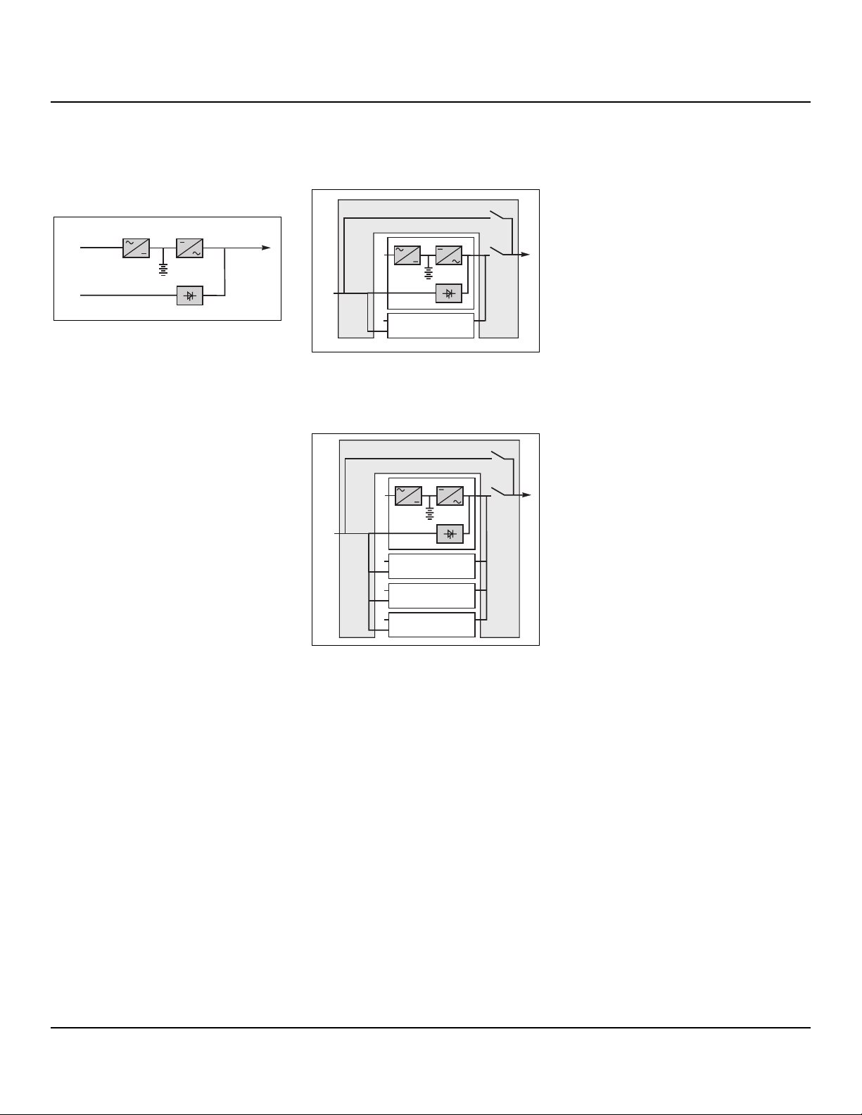
system description
(see figure 1)
■ a rectifier/charger module (A) converts
3-phase AC power from the normal AC
source supply (1) into DC power for the
normal inverter input and float charges or
recharges the battery;
■ a battery unit (D) provides backup
power for the inverter in the event of a
voltage drop or a normal AC source failure;
■ an inverter module (B) converts the DC
power supplied by the rectifier/charger
module or the battery unit into 3-phase AC
power for the load;
■ a static bypass module (C) ensures the
instantaneous transfer of the load to the
bypass AC source input in the event of an
inverter shutdown (initiated by the user or
by a protective device) or a sudden overload;
■ a maintenance bypass isolates the UPS
for maintenance and transfers the load to
bypass AC source input without interrupting the supply of power. The maintenance
bypass is made up of three manual
switches (Q3BP, Q4S and Q5N).
Note
■ the normal AC input and the bypass AC
input have different functions and,
depending on the installation, may be protected differently upstream and/or come
from different sources.
■ when increased power is required, sev-
eral Galaxy PW™ units may be connected in parallel (up to four). In this configuration, an "isolation" function is added for
the UPS system as a whole for maintenance purposes, without interrupting the
supply of power to the load.
The system may also include:
■ Isolation or auto transformers on both
input and output.
■ 2 CB or 3 CB maintenance bypass
■ different remote control, indication and
display systems.
Introduction
Fig. 1 *The Fuse is to protect against catastrophic rectifier/inverter
semiconductor failure.
Schematic diagram of the Galaxy PW™ system
maintenance bypass:
Q3BP
inverter (B):
DC to AC
power
isolation:
Q4S
isolation and
protection:
Q5N
rectifier/
charger (A):
AC to DC
power
QF1: isolation
and protection
normal
AC input
load
battery (D):
backup power
static bypass (C):
bypass
AC input
Q1
isolation
and
protection
(1)
(2)
harmonic
fliter
*FUSE
*FUSE
Galaxy PWTM100 to 225 kVA
5
different types of Galaxy
PW™ systems
single-UPS unit
Fig. 2
parallel UPS system
See figure 3 showing two parallel-connected (redundant) UPS units.
Fig. 3
When increased power is required (two to
four parallel units), an external bypass
must be added (see figure 4).
Fig. 4
isolation and protection
devices
(See figure 1 on previous page):
■ Q1 (Molded circuit breaker NA):
❏ isolation of the rectifier/charger (A) from
the normal AC source (1);
❏ rectifier/charger (A) start-up;
■ QF1 (circuit breaker):
❏ battery (D) protection and isolation;
■ Q5N (switch):
❏ isolation of the UPS (B) from the load;
■ Q4S (switch):
❏ isolation of the static bypass (C) from
the bypass AC source (2);
■ Q3BP (switch):
❏ bypass switch for maintenance;
■ FUE (fuses):
❏ protection of the rectifier/charger (A)
from the normal AC source;
■ FUS (fuses):
❏ protection of the inverter (B) from the
load.
Note:
■ switch Q3BP is lock on open position on
parallel UPS systems constituted to
increase available power.
external bypass for parallel
UPSs and the hot-swap
option
See figure 4.
■ Q5N: isolation of the inverters of all the
parallel UPS systems from the load;
■ Q3BP: bypass for maintenance.
2
1
Q3BP
Galaxy 1
Galaxy 2
2
1
Galaxy 3
2
1
Galaxy 4
2
2
Q5N
1
2
1
Q3BP
S
Galaxy 1
Galaxy 2
2
2
Q5N
1
1
2
AB
C
D
User’s Manual
Introduction
6 Introduction
operation in on-line
mode
normal operation
Normal AC source power is available (see
figure 5).
■ lights 1 , 4 and 5 shine green on
the control panel;
■ the power necessary for the load is pro-
vided by the normal AC source (1) through
the rectifier/charger (A) and the inverter
(B);
■ the rectifier/charger (A) also supplies
the power to float charge and recharge the
battery if any.
The rectifier/charger output voltage (DC) is
regulated to supply:
❏ the float-charging or the recharging volt-
age for vented lead-acid or Ni/Cd batteries,
❏ a single charge voltage for sealed lead-
acid batteries.
The voltages depend on the number of
battery cells and the battery manufacturer.
Factory set, they may also be adjusted by
after-sales support technicians.
An electronic board continuously measures the battery temperature and automatically adjusts the voltages.
Note:
In parallel Galaxy PW™ systems, the
power drawn by the load is equally shared
between the different units.
Fig. 5
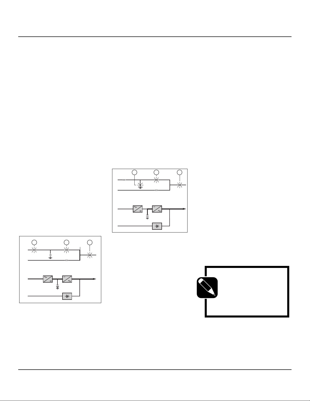
operation with the normal AC
source down
See figure 6.
In the event of a normal AC source failure
or voltage outside specified tolerances of
±10% in amplitude (±15% optionally), the
rectifier/charger (A) stops and the battery
(D) supplies the necessary backup power
to the load via the inverter (B). The battery, float-connected between the rectifier/charger and the inverter, discharges
during this operating mode.
Lights 2 , 4 and 5 shine green.
The user is warned of battery operation by
the slow beeping of the buzzer 6 (see
figure 16) and the message "LOAD PROTECTED, BATTERY DISCHARGING", followed by the remaining backup time and
the percent load.
This information is also available via voltfree changeover contacts for remote control devices.
Fig. 6
battery time
The available battery time during a normal
AC source outage depends on the:
■ rated capacity of the battery;
■ power consumed by the load;
■ temperature of the battery;
■ age of the battery.
The specified battery time corresponds to
a minimum duration at full rated load.
The actual backup time can therefore be
greater if the system operates below its
full rated load during the normal AC
source outage. Operation on battery
power can be extended beyond the specified time by reducing the load power consumption (by disconnecting non-critical
loads).
A "low battery" warning signal is sent via
volt-free changeover contacts for remote
control devices when the battery voltage
reaches a level slightly above the minimum level. This signal warns the user of
the imminent end of battery power. On the
device itself, the buzzer beeps rapidly.
The message "LOW-BATTERY SHUTDOWN WARNING" is displayed, followed
by the remaining backup time and the percent load. Light 2 turns red and flashes.
Battery power stops when the voltage
supplied by the battery reaches the minimum threshold. This results in inverter
shutdown and transfer of the load without
interruption to the bypass AC source. Light
2 shines red (not flashing). The message "LOAD NOT PROTECTED, ONLINE MODE" is displayed and the buzzer
sounds continuously.
If the bypass AC source also fails, the
load is no longer supplied. The inverter
automatically shuts down when the time
on battery power exceeds three times the
specified backup time.
NOTE
The "low battery shutdown" warning signal can
be sent with an adjustable
time delay prior to the
effective end of battery
power.
1
2
AB
C
D
2
1
4
5
1
Galaxy PWTM100 to 225 kVA
4 52
1
2
AB
1
D
C
2
 Loading...