


w w w . m g e u p s . c o m
EPS 7000
Single Module
Users Manual

EPS 7000 Single Module
IMPORTANT SAFETY INSTRUCTIONS
SAVE THESE INSTRUCTIONS – This manual contains important instructions for all EPS 7000 Single Module that must be followed during operation of the equipment.
WARNING: |
Opening enclosures expose hazardous voltages. Always refer |
|
service to qualified personnel only. |
ATTENTION: |
L'ouverture des cabinets expose des tensions dangereuses. |
|
Assurez-vous toujours que le service ne soit fait que par des |
|
personnes qualifiees. |
WARNUNG! |
Das öffnen der Gehäuse legen gefährliche Spannungen bloss. |
|
Service sollte immer nur von qualifizierten Personal durchgeführt |
|
werden. |
|
|
|
|
WARNING: |
As standards, specifications, and designs are subject to change, |
|
|
please ask for confirmation of the information given in this |
|
|
publication. |
|
ATTENTION: |
Comme les normes, spécifications et produits peuvent changer, |
|
|
veuillez demander confirmation des informations contenues dans |
|
|
cette publication. |
|
WARNUNG! |
Normen, Spezifizierungen und Pläne unterliegen Anderungen. |
|
|
Bitte verlangen Sie eine Bestätigung über alle Informationen, die in |
|
|
dieser Ausgabe gemacht wurden. |
|
|
|
|
|
|
|
NOTE: |
This equipment generates, uses, and can radiate radio |
|
frequency energy and, if not installed and used in accordance |
|
with installation manual, may cause harmful interference to |
|
radio communications. Operation of this equipment in a |
|
residential area is likely to cause harmful interference in which |
|
case the user will be required to correct the interference at his |
|
own expense. |
|
|
|
|
page ii |
Important Safety information |

Users Manual
EPS 7000
Single Module
Users Manual
For service call
1-800-523-0142
86-134004-00 X0 08/04
Copyright © 2004 MGE UPS SYSTEMS, Inc. All rights reserved. Printed in U.S.A.
MGE UPS SYSTEMS, Inc.
1660 Scenic Avenue Costa Mesa, CA 92626 (714) 557-1636
page iii

EPS 7000 Single Module
EPS 7000
Single Module Users Manual
Warranty
The liability of MGE UPS SYSTEMS, Inc. hereunder is limited to replacing or repairing at MGE UPS SYSTEMS, Inc.’s factory or on the job site at MGE UPS SYSTEMS, Inc.’s option, any part or parts which are defective, including labor, for a period of 12 months from the date of purchase. The MGE UPS SYSTEMS, Inc. shall have the sole right to determine if the parts are to be repaired at the job site or whether they are to be returned to the factory for repair or replacement. All items returned to MGE UPS SYSTEMS, Inc. for repair or replacement must be sent freight prepaid to its factory. Purchaser must obtain MGE UPS SYSTEMS, Inc.’s Return Materials Authorization prior to returning items. The above conditions must be met if warranty is to be valid. MGE UPS SYSTEMS, Inc. will not be liable for any damage done by unauthorized repair work, unauthorized replacement parts, from any misapplication of the item, or for damage due to accident, abuse, or Act of God.
In no event shall the MGE UPS SYSTEMS, Inc. be liable for loss, damage, or expense directly or indirectly arising from the use of the units, or from any other cause, except as expressly stated in this warranty. MGE UPS SYSTEMS, Inc. makes no warranties, express or implied, including any warranty as to merchantability or fitness for a particular purpose or use. MGE UPS SYSTEMS, Inc. is not liable for and Purchaser waives any right of action it has or may have against MGE UPS SYSTEMS, Inc. for any consequential or special damages arising out of any breach of warranty, and for any damages Purchaser may claim for damage to any property or injury or death to any person arising out of its purchase of the use, operation or maintenance of the product. MGE UPS SYSTEMS, Inc. will not be liable for any labor subcontracted or performed by Purchaser for preparation of warranted item for return to MGE UPS SYSTEMS, Inc.’s factory or for preparation work for field repair or replacement. Invoicing of MGE UPS SYSTEMS, Inc. for labor either performed or subcontracted by Purchaser will not be considered as a liability by the MGE UPS SYSTEMS, Inc.
This warranty shall be exclusive of any and all other warranties express or implied and may be modified only by a writing signed by an officer of the MGE UPS SYSTEMS, Inc. This warranty shall extend to the Purchaser but to no one else. Accessories supplied by MGE UPS SYSTEMS, Inc., but manufactured by others, carry any warranty the manufacturers have made to MGE UPS SYSTEMS, Inc. and which can be passed on to Purchaser.
MGE UPS SYSTEMS, Inc. makes no warranty with respect to whether the products sold hereunder infringe any patent, U.S. or foreign, and Purchaser represents that any specially ordered products do not infringe any patent. Purchaser agrees to indemnify and hold MGE UPS SYSTEMS, Inc. harmless from any liability by virtue of any patent claims where Purchaser has ordered a product conforming to Purchaser’s specifications, or conforming to Purchaser’s specific design.
Purchaser has not relied and shall not rely on any oral representation regarding the Product sold hereunder and any oral representation shall not bind MGE UPS SYSTEMS, Inc. and shall not be part of any warranty.
There are no warranties which extend beyond the description on the face hereof. In no event shall MGE UPS SYSTEMS, Inc. be responsible for consequential damages or for any damages except as expressly stated herein.
Service and Factory Repair - Call 1-800-523-0142
Direct questions about the operation, repair, or servicing of this equipment to MGE UPS SYSTEMS, Inc. Technical Support Services. Include the part number and serial number of the unit in any correspondence. Should you require factory service for your equipment, contact MGE UPS SYSTEMS, Inc. Technical Support Services and obtain a Return Materials Authorization (RMA) prior to shipping your unit. Never ship equipment to MGE UPS SYSTEMS, Inc. without first obtaining an RMA.
Proprietary Rights Statement
The information in this manual is the property of MGE UPS SYSTEMS, Inc., and represents a proprietary article in which MGE UPS SYSTEMS, Inc., retains any and all patent rights, including exclusive rights of use and/or manufacture and/or sale. Possession of this information does not convey any permission to reproduce, print, or manufacture the article or articles shown herein. Such permission may be granted only by specific written authorization, signed by an officer of MGE UPS SYSTEMS, Inc.
IBM, PC-AT, ES/9000, and AS/400 are trademarks of International Business Machines Corporation. MGE and MGE UPS SYSTEMS are trademarks of MGE UPS SYSTEMS, Inc. Other trademarks that may be used herein are owned by their respective companies and are referred to in an editorial fashion only.
Revision History
EPS 7000 Single Module Users Manual |
|
|
|
86-134004-00 |
|
|
|
Copyright © 2003 MGE UPS SYSTEMS, Inc. |
All rights reserved |
Printed in U.S.A. |
|
Revision: X0 |
R&D-001651 |
08/2004 |
|
page iv |
Warranty Information |
Users Manual
How To Use This Manual
This manual is designed for ease of use and easy location of information.
To quickly find the meaning of terms used within the text, look to the Glossary.
To quickly find a specific topic, look at the Table of Contents.
This manual uses Note lines and icons to convey important information.
Note lines and icons come in four variations.
WARNING: |
Indicates information provided to protect the User and |
|
service personnel against safety hazards and possible |
|
equipment damage. |
|
|
|
|
CAUTION: |
Indicates information provided to protect the User and |
|
service personnel against possible equipment damage. |
|
|
|
|
NOTE: |
Indicates information provided as an operating tip or an |
|
equipment feature. |
|
|
|
|
IMPORTANT: |
Indicates information provided as an operating instruction |
|
or as a tip. |
|
|
|
|
How To Use This Manual |
page v |

EPS 7000 Single Module
CAUTION
RECORD ALL SERIAL NUMBERS FOR THE SINGLE MODULE UPS SYSTEM.
THESE SERIAL NUMBERS WILL BE REQUIRED IF YOUR SYSTEM NEEDS SERVICE. KEEP THIS MANUAL IN A PLACE WHERE YOU CAN REFERENCE THE SERIAL NUMBERS IF SERVICE IS REQUIRED!
UPS UNIT SERIAL NUMBER: _____________________________________________
MBP CABINET SERIAL NUMBER: ________________________________________
ADDITIONAL SERIAL NUMBERS:
__________________________ ______________________________
__________________________ ______________________________
__________________________ ______________________________
__________________________ ______________________________
__________________________ ______________________________
__________________________ ______________________________
__________________________ ______________________________
__________________________ ______________________________
__________________________ ______________________________
__________________________ ______________________________
CAUTION: Record All Serial Numbers |
page vi |

Users Manual
C o n t e n t
section |
description . . . . . . . . . . . . . . . . . . . . . . . . . . . . . . |
. . . . . . . . . . .page |
|
Important Safety Instructions . . . . . . . . . . . . . . . . . |
Inside Front Cover |
|
Warranty . . . . . . . . . . . . . . . . . . . . . . . . . . . . . . . . |
. . . . . . . . . . . . .ivi |
|
Revision History . . . . . . . . . . . . . . . . . . . . . . . . . . . |
. . . . . . . . . . . . .iv |
|
How To Use This Manual . . . . . . . . . . . . . . . . . . . . |
. . . . . . . . . . . . .v |
|
CAUTION: Record All Serial Numbers . . . . . . . . . |
. . . . . . . . . . . .vi |
|
Table of Contents . . . . . . . . . . . . . . . . . . . . . . . . . . . |
. . . . . . . . . . .c-i |
Section 1 Introduction
section |
description |
. . . . . . . . . . . . . . . . . . . . . . . . . . . . . . . . . . . |
. . .page |
1.0 |
Scope . . . . |
. . . . . . . . . . . . . . . . . . . . . . . . . . . . . . . . . . . |
. . . .1-1 |
1.1 |
Reference Manuals . . . . . . . . . . . . . . . . . . . . . . . . . . . . . |
. . .1-1 |
|
1.2 |
Section Descriptions . . . . . . . . . . . . . . . . . . . . . . . . . . . . . |
. . .1-1 |
|
1.3 |
General Description . . . . . . . . . . . . . . . . . . . . . . . . . . . . . . |
. . .1-2 |
|
1.4 |
Specifications, Circuit Breakers and Powerflow Diagrams |
. . . .1-3 |
|
1.4.1 |
Circuit Breakers . . . . . . . . . . . . . . . . . . . . . . . . . . . . . . . . . |
. . .1-3 |
|
1.4.2 |
Power Flow Diagrams . . . . . . . . . . . . . . . . . . . . . . . . . . . . |
. . .1-5 |
|
|
1.4.2.1 |
Normal Operation . . . . . . . . . . . . . . . . . . . . . |
. . .1-5 |
|
1.4.2.2 |
On-Battery Operation . . . . . . . . . . . . . . . . . . . |
. . .1-5 |
1.5 |
Single Module Indicators and Controls . . . . . . . . . . . . . . . |
. . .1-6 |
|
1.5.1 |
Front Panel . |
. . . . . . . . . . . . . . . . . . . . . . . . . . . . . . . . . . . |
. . .1-7 |
1.5.2 |
Alphanumeric Display and Controls . . . . . . . . . . . . . . . . . . |
. . .1-8 |
|
|
1.5.2.1 |
Two-line Alphanumeric Display . . . . . . . . . . . |
. . .1-8 |
|
1.5.2.2 |
Alphanumeric Display Pushbuttons Descriptions .1-9 |
|
|
1.5.2.3 |
Numbered Lights . . . . . . . . . . . . . . . . . . . . . . |
. .1-10 |
1.5.3 |
Hidden Panel Indicators . . . . . . . . . . . . . . . . . . . . . . . . . . . |
. .1-10 |
|
|
1.5.3.1 |
LED Alphanumeric Indicator . . . . . . . . . . . . . |
. .1-11 |
|
1.5.3.2 Hidden Panel Lower Pushbuttons . . . . . . . . . |
. .1-12 |
|
Contents |
page c i |

EPS 7000 Single Module
Section 2 Operation |
|
|
section |
description . . . . . . . . . . . . . . . . . . . . . . . . . . . . . . . . . . . |
. . .page |
2.0 |
Scope . . . . . . . . . . . . . . . . . . . . . . . . . . . . . . . . . . . . . . . |
. . . .2-1 |
2.1 |
Status Screen Display . . . . . . . . . . . . . . . . . . . . . . . . . . . . |
. . .2-1 |
2.2 |
Settings Selection Screen . . . . . . . . . . . . . . . . . . . . . . . . . |
. . .2-2 |
2.3 |
Alarms . . . . . . . . . . . . . . . . . . . . . . . . . . . . . . . . . . . . . . . . |
. . .2-2 |
2.4 |
Sensor Measurements . . . . . . . . . . . . . . . . . . . . . . . . . . . . |
. . .2-3 |
2.5 |
Voltage Measurements . . . . . . . . . . . . . . . . . . . . . . . . . . . |
. . .2-4 |
2.6 |
Current Measurements . . . . . . . . . . . . . . . . . . . . . . . . . . . |
. . .2-5 |
2.7 |
Power Frequency Measurements . . . . . . . . . . . . . . . . . . . |
. . .2-6 |
2.8 |
Battery Measurements . . . . . . . . . . . . . . . . . . . . . . . . . . . . |
. . .2-7 |
2.9 |
LCD Messages . . . . . . . . . . . . . . . . . . . . . . . . . . . . . . . . . |
. . .2-8 |
2.9.1 |
General Alarms . . . . . . . . . . . . . . . . . . . . . . . . . . . . . . . . . |
. . .2-8 |
2.9.2 |
Secondary Alarms . . . . . . . . . . . . . . . . . . . . . . . . . . . . . . . |
. . .2-8 |
2.10 |
Preparations Before Start-up . . . . . . . . . . . . . . . . . . . . . . . |
. .2-12 |
2.10.1 |
Checks Before Start-up . . . . . . . . . . . . . . . . . . . . . . . . . . . |
. .2-12 |
2.10.2 |
Start-up . . . . . . . . . . . . . . . . . . . . . . . . . . . . . . . . . . . . . . . |
. .2-12 |
2.10.3 |
Checks After Start-up . . . . . . . . . . . . . . . . . . . . . . . . . . . . . |
. .2-13 |
2.11 |
Shutdown . . . . . . . . . . . . . . . . . . . . . . . . . . . . . . . . . . . . . |
. .2-13 |
2.11.1 |
Emergency Shutdown Using EPO . . . . . . . . . . . . . . . . . . . |
. .2-14 |
2.11.2 |
Normal Shutdown . . . . . . . . . . . . . . . . . . . . . . . . . . . . . . . |
. .2-14 |
2.11.3 |
With Maintenance Bypass . . . . . . . . . . . . . . . . . . . . . . . . . |
. .2-14 |
2.11.4 |
Without Maintenance Bypass . . . . . . . . . . . . . . . . . . . . . . |
. .2-15 |
2.12 |
Forced Transfers . . . . . . . . . . . . . . . . . . . . . . . . . . . . . . . . |
. .2-16 |
2.12.1 |
Uninterrupted Transfer Conditions . . . . . . . . . . . . . . . . . . . |
. .2-16 |
2.12.2 |
Forced Transfer from Bypass AC Input Source to Inverter |
. . .2-16 |
2.12.3 |
Forced Transfer from Inverter to Bypass AC Input . . . . . . . |
. .2-16 |
Section 3 |
Maintenance |
|
|
|
section |
description . . . . . . . . . . . . . . . . . . . . . . . . . . . . . . . . . . . . . . |
page |
|
3.0 |
Scope . . . . . . . . . . . . . . . . . . . . . . . . . . . . . . . . . . . . . . . . . . |
.3-1 |
|
3.1 |
Safety Instructions . . . . . . . . . . . . . . . . . . . . . . . . . . . . . . . . . |
.3-1 |
|
3.2 |
Important Safety Instructions for Servicing Batteries . . . . . . . . |
.3-1 |
|
3.3 |
Preventive Maintenance . . . . . . . . . . . . . . . . . . . . . . . . . . . . |
.3-2 |
|
3.4 |
Replacement Parts . . . . . . . . . . . . . . . . . . . . . . . . . . . . . . . . |
.3-2 |
Glossary |
g-1 |
|
|
page c ii |
Contents |

Users Manual
Figures
figure |
description . . . . . . . . . . . . . . . . . . . . . . . . . . . . . . . . . . . . . . |
. . .page |
1-1 |
EPS 7000 System, Single-Module Configuration, |
|
|
1 GCC per Module . . . . . . . . . . . . . . . . . . . . . . . . . . . . . . |
. . . .1-2 |
1-2 |
Circuit Breaker Locations on the EPS 7000. (Q4S not shown) |
. . . .1-3 |
1-3 |
Circuit Breaker Locations on the Maintenance Bypass Cabinet |
. . .1-4 |
1-4 |
Normal Operation, Power Flow Diagram . . . . . . . . . . . . . . . . . |
. . .1-5 |
1-5 |
On-Battery Operation, Power Flow Diagram . . . . . . . . . . . . . . . |
. . .1-5 |
1-6 |
EPS 7000 Front Panel Indicators and Controls. . . . . . . . . . . . . . . .1-6 |
|
1-7 |
Front Panel Indicators and Control Display . . . . . . . . . . . . . . . |
. . .1-7 |
1-8 |
Alphanumeric Display and Controls . . . . . . . . . . . . . . . . . . . . . |
. . .1-8 |
1-9 |
Hidden Panel Indicator Controls . . . . . . . . . . . . . . . . . . . . . . . . |
. .1-10 |
2-1 |
Default Status Screen Alphanumerical Display Configuration. . . |
. . .2-1 |
2-2 |
Settings Selection Display Screen. . . . . . . . . . . . . . . . . . . . . . . . .2-2 |
|
2-3 |
Sequential Alarm Messages for Viewing the Fault Log . . . . . . . |
. . .2-3 |
2-4 |
Measurement Sensors Located throughout the EPS 7000 |
|
|
Single-Module UPS . . . . . . . . . . . . . . . . . . . . . . . . . . . . . . . . . |
. . .2-3 |
2-5 |
Voltage Measurement Displays . . . . . . . . . . . . . . . . . . . . . . . . |
. . .2-4 |
2-6 |
Current Measurements Displays . . . . . . . . . . . . . . . . . . . . . . . |
. . .2-5 |
2-7 |
Power and Frequency Measurements Displays . . . . . . . . . . . . |
. . .2-6 |
2-8 |
Battery Measurements Displays . . . . . . . . . . . . . . . . . . . . . . . . |
. . .2-7 |
Contents |
page c iii |

EPS 7000 Single Module
(This page left blank intentionally)
page c iv
Users Manual
I n t r o d u c t i o n
1.0Scope
This manual provides User instructions for operating the EPS 7000 Single Module system (S-M). Descriptions include section descriptions, a general overview of system internal components, circuit breaker diagrams, descriptions for front panel displays and control indicators.
Please read this manual before installing the EPS 7000 equipment. Please retain this manual for future reference.
1.1Reference Manuals
The EPS 7000 Installation Manual (MGE part number 86-134003-00) provides technical information required for installation and maintenance of EPS 7000 Single Module and Shared Systems. The EPS 7000 Shared Systems Users Manual, (MGE part number 86-134005-00) provides detailed operating instructions for shared systems.
86-134005-00 EPS 7000 Users Manual, Shared System
86-134003-00 EPS 7000 Installation Manual, Single Module and Shared Systems 86-132204-00 Graphical Command Center, User Manual
1.2Section Descriptions
This manual is divided into four sections:
Section 1 Introduction
This section provides User instructions for operating the EPS 7000 Single Module system. Descriptions include section descriptions, a general overview of system internal components, circuit breaker diagrams, descriptions for front panel displays and control indicators.
Section 2 Operation
This section describes procedures for normal operation of EPS 7000 Single Module systems. Including interactive front panel display, settings for language configuration, alarms message displays, voltage, current, battery measurements, with before and after start-up checks, emergency shutdown using EPO disconnects, and normal conditions for using forced transfers.
Section 3 Maintenance
This section describes maintenance of the EPS 7000, including troubleshooting LCD alarm message, safety instructions, preventive maintenance, isolation for maintenance, and information about replacement parts.
A Glossary in the rear of this manual provides definitions of terms used within the text.
Introduction |
page 1 — 1 |
EPS 7000 Single Module
1.3General Description
EPS 7000 is a family of compact, high-efficiency uninterruptible power systems. Standard power ratings for singlemodule systems range from 300 to 500 kVA. EPS 7000 are optimized for compatibility with non-linear computer-type loads. Computer-aided UPS diagnostics and modular construction assures that any required service on the UPS can be identified and completed rapidly. Remote system monitoring, remote annunciation of UPS performance signals, and telecommunication capabilities allow total control of the UPS by the user.
The EPS 7000, SSC, battery, and all auxiliary equipment is listed for safety by Underwriter’s Laboratories, Inc. (UL) under UL Standard 1778 and under Canadian Standards Association (CSA) standard C22.107.
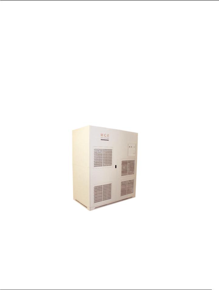
Major components of the EPS 7000 Single Module include:
UPS Single Module
UPS maintenance bypass cabinet
UPS bypass cabinet
Battery disconnect
Each of these cabinets is described below. Figure 1-1 shows a single-module UPS.
Figure 1-1: EPS 7000 System, Single-Module Configuration, 1 GCC per Module.
page 1 — 2 |
Introduction |
Users Manual
1.4 Specifications, Circuit Breakers and Powerflow Diagrams
1.4.1 Circuit Breakers
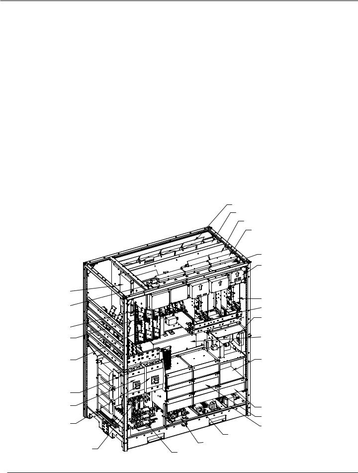
EPS 7000 circuit breakers (except the battery disconnect circuit breaker QF1) are located behind the doors of the Input/Output cabinet. Following is a brief description of the available circuit breakers and contacts, and their function (Figures 1-2, 1-3, and 1-4).
Q1 |
Input isolation circuit breaker, used to isolate the UPS from the main AC input (mains 1) and provide |
|
input current protection. |
QF1 |
Battery disconnect circuit breaker, external to the UPS, used to disconnect the battery from the UPS. |
|
QF1 provides isolation and protection between the UPS and its battery system. |
Q3BP |
(optional) Maintenance bypass circuit breaker, used to supply the attached load via the bypass source |
|
while the UPS is being serviced. |
Q5N |
Optional UPS isolation circuit breaker, used to isolate the UPS module from the attached load. |
Q4S |
Bypass input circuit breaker; it is used to isolate the UPS from the bypass input (mains 2) source and |
|
provide back-feed protection. |
Figure 1-2: Circuit Breaker Locations on the EPS 7000.
MULTI-SLOT (OPTION)
MODEM AND PWR
SUPPLY (OPTION)
BYPASS
STATIC
SWITCH
RECTIFIER
OUTPUT
STATIC
SWITCH
SERIES
FILTER
CHOKES 
CONTROL
FUSES
Q1
INPUT CB
Q4S
BYPASS CB
INPUT
FUSES
BLOWERS (4X)
BLOWERS (4X)
BLOWERS (3X)
RAUZ2 PCA (OPT)
RAUZ PCA
IBEZ PCA
OBEZ PCA
BAIZ1 PCA
TREZ PCA
SSSZ PCA
ALBZ PCA
EPOZ PCA
INVERTERS (6X)
DC CAPS
ACOZ PCA
ACUZ PCA
ARUZ PCA
OUTPUT XFMR (BEHIND PANEL)
CARD CAGE
ALEZ PCA
AROZ—US PCA
CROZ—US PCA
CRIZ—US PCA
SRIZ PCA
GTCZ—7000 PCA
GT2Z—7000 PCA (OPT.)
INPUT FILTER (3X)
OUTPUT FILTER (4X)
FAN XFMRS GUI POWER SUPPLY
OUTPUT FUSES INPUT FILTER FUSES
Introduction |
page 1 — 3 |

EPS 7000 Single Module
Figure 1-3: Circuit Breaker Locations on the Maintenance Bypass Cabinet.
page 1 — 4 |
Introduction |
Users Manual
1.4.2 Power Flow Diagrams
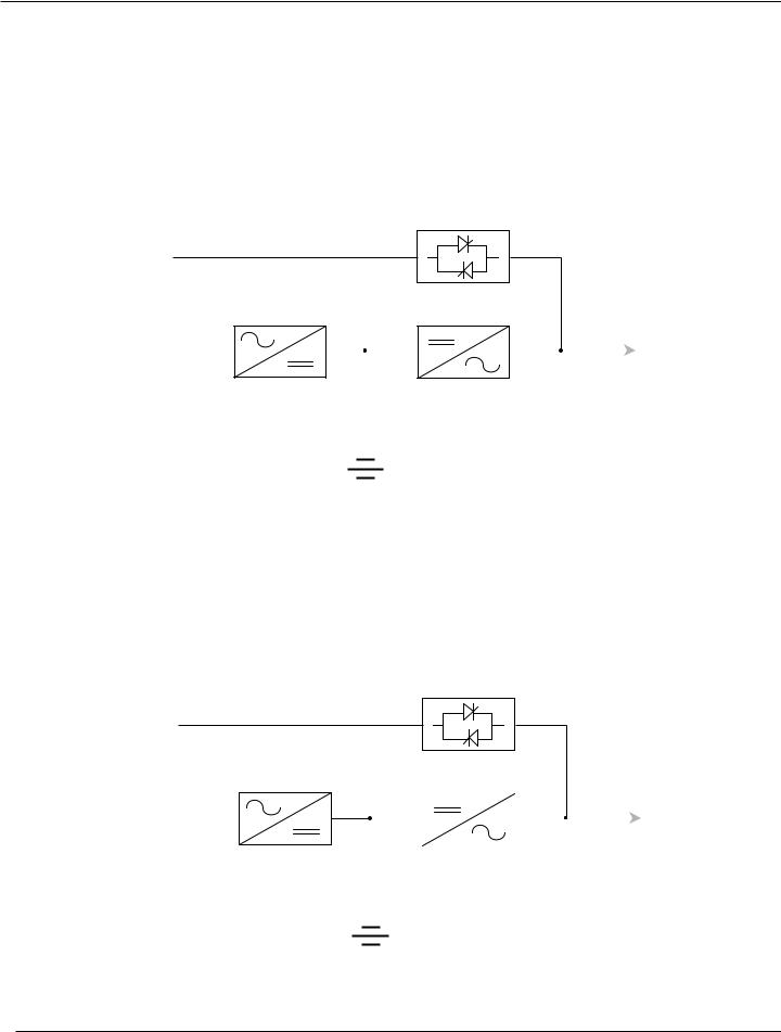
1.4.2.1 Normal Operation
During normal operation, power flows from the main AC input source (mains 1) into the UPS rectifier/battery charger section. The rectifier/battery charger converts the AC voltage to DC, maintains the charge of the battery, and feeds the DC power to the inverter. The inverter regenerates AC voltage, and supplies the attached load. See Figure 1-5.
Figure 1-4: Normal Operation, Power Flow Diagram.
Static switch
Bypass AC input (mains 2)
|
|
Rectifier/battery |
|
|
Inverter |
||||
|
|
charger |
|
|
|||||
Main AC input |
|
|
|
|
Attached |
||||
(mains 1) |
|
|
|
|
|
|
|
|
load(s) |
|
|
|
|
|
|
|
|||
|
|
|
|
|
|
|
|
|
|
|
|
|
|
|
|
|
|
|
|
Battery
1.4.2.2 On-Battery Operation
If the main AC input source (mains 1) fails or goes out of tolerance, the charger stops. Power flows from the battery to the UPS inverter, which in turn supplies the attached load. When the main AC input source (mains 1) returns, the charger restarts automatically and the UPS resumes its normal operation. See Figure 1-6.
If the battery becomes depleted before the main AC input source (mains 1) returns, the inverter stops and the attached load is transferred to the bypass AC input source (mains 2) if it is available.
Figure 1-5: On-Battery Operation, Power Flow Diagram.
Static switch
Bypass AC input (mains 2)
|
|
Rectifier/battery |
|
|
|
Inverter |
|||
|
|
charger |
|
|
|
||||
Main AC input |
|
|
|
|
|
Attached |
|||
|
|
|
|
|
|||||
(mains 1) |
|
|
|
|
|
|
|
|
load(s) |
|
|
|
|
|
|
|
|
||
|
|
|
|
|
|
|
|
|
|
|
|
|
|
|
|
|
|
|
|
|
|
|
|
|
|
|
|
|
|
Battery
Introduction |
page 1 — 5 |
EPS 7000 Single Module
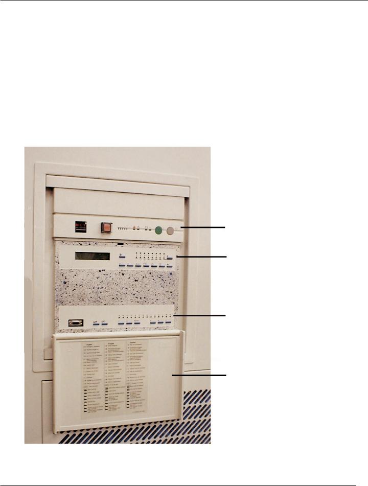
1.5Single Module Indicators and Controls
Single Module indicators and controls are located in three places on the UPS cabinet: on the front panel, behind a drop-down cover just below the front panel, and inside the cabinet doors, see Figure 1-7. In battery cabinets and auxiliary cabinets, the controls are located behind the cabinet doors.
The following display descriptions:
Front Panel
Alphanumeric Display
Hidden Panel
Figure 1-6: EPS 7000 Front Panel Indicators and Controls.
Front Panel
Alphanumeric
Display
Hidden Panel
Cover Plate
page 1 — 6 |
Introduction |
 Loading...