


www.mgeups.com |
MGE UPS SYSTEMS |
Comet
EX 5 RT 3:1
EX 7 RT 3:1
EX 11 RT 3:1
R
E
T
N
I
N
U
E
H
T
R
U
P
T
I
B
L
P |
O |
|
E
E
W
Installation and user manual
|
|
|
|
I |
D |
E |
R |
|
|
|
V |
|
|||
|
|
|
|
|
|||
|
|
O |
|
|
|
||
|
R |
|
|
|
|
||
|
|
|
|
|
|
||
P |
|
|
|
|
|
|
|
|
|
|
|
|
|
|
R
34007724EN/AA - Page 1

Introduction
Thank you for selecting an MGE UPS SYSTEMS product to protect your equipment.
The Comet EX RT range has been designed with the utmost care.
We recommend that you take the time to read this manual to take full advantage of the many features of your UPS.
Warning: this is a class A UPS product. In a domestic environment, this product may cause radio interference, in which case, the user may be required to take additional measures.
If the device must be installed in overvoltage category III or IV environments, additional upstream overvoltage protection must be provided for.
To discover the entire range of MGE UPS SYSTEMS products and the options available for the Comet EX RT range, we invite you to visit our web site at www.mgeups.com or contact your MGE UPS SYSTEMS representative.
Environmental protection
MGE UPS SYSTEMS cares about the environmental impact of its products and has therefore implemented an eco-design process for the entire life cycle of the Comet EX RT product: design, usage and recycling.
Using this document
Information may be found primarily by checking:the contents,
the index.
Icons
Important instructions that must always be followed.
Information, tips, help.
Visual indication.
Action.
Audible alarm.
In the illustrations on the following pages, the symbols below are used:
LED off.
LED on.
LED flashing.
Page 2 - 34007724EN/AA
Contents
1.Presentation
1.1 |
Standard configurations .............................................................................................................. |
5 |
|
Tower configuration ......................................................................................................................... |
5 |
|
Rack configuration .......................................................................................................................... |
5 |
1.2 |
Rear panels.................................................................................................................................... |
6 |
|
Power module Comet EX 5 RT / EX 7 RT / EX 11 RT .................................................................... |
6 |
|
Battery module Comet EXB 7 RT / EXB 11 RT ............................................................................... |
6 |
1.3 |
Display and control panel ............................................................................................................ |
7 |
1.4 |
Options .......................................................................................................................................... |
7 |
|
Rack mounting kits .......................................................................................................................... |
7 |
|
Transformer for galvanic isolation or earthing arrangement change .............................................. |
8 |
|
Battery extensions for UPS backup times up to 60 minutes ........................................................... |
9 |
|
CLA module (Long backup time charger) for backup times from 2 to 8 hours ................................ |
9 |
|
Modules integration system .......................................................................................................... |
10 |
|
Battery module with Remote Emergency Power Off function (REPO) ......................................... |
10 |
|
Battery extension cable (1,8 m / 6 ft) ............................................................................................ |
10 |
2.Installation
2.1 |
Unpacking and parts check ....................................................................................................... |
11 |
|
Power module ............................................................................................................................... |
11 |
|
Battery module .............................................................................................................................. |
11 |
2.2 |
Installation in tower configuration ............................................................................................ |
12 |
2.3 |
Installation in rack configuration .............................................................................................. |
13 |
|
Adjustment of the orientation of the logo and control panels ........................................................ |
13 |
|
Battery module rack mounting (optional rail required) .................................................................. |
13 |
|
Power or battery module rack mounting (optional rail required) ................................................... |
14 |
2.4 |
Communication ports ................................................................................................................. |
16 |
|
Connection to the RS232 communication port ............................................................................. |
16 |
|
Connection to the communications port by relays ........................................................................ |
16 |
|
Remote Power Off communication port ........................................................................................ |
17 |
|
Installation of communication cards (optional, standard with the Network Pack version)............. |
17 |
2.5 |
Installation depending on the system earthing arrangement (SEA) ...................................... |
18 |
|
UPS with common Normal and Bypass AC inputs........................................................................ |
18 |
|
UPS with separate Normal and Bypass AC inputs ....................................................................... |
18 |
|
UPS with separate Normal and Bypass AC inputs, supplied by separate sources....................... |
19 |
|
Frequency converter (without Bypass AC input) ........................................................................... |
19 |
|
Hot standby ................................................................................................................................... |
19 |
2.6 |
Required protective devices and cable cross-sections .......................................................... |
20 |
|
Recommended upstream protection ............................................................................................. |
20 |
|
Recommended downstream protection ........................................................................................ |
20 |
|
Required cable cross-section........................................................................................................ |
20 |
2.7 |
Connections of input/output power cables .............................................................................. |
21 |
|
UPS with common Normal and Bypass AC sources..................................................................... |
21 |
|
UPS with separate Normal and Bypass AC sources .................................................................... |
22 |
|
Frequency converter ..................................................................................................................... |
23 |
|
Connection of battery cables ........................................................................................................ |
24 |
|
Connection of galvanic isolation transformer ................................................................................ |
24 |
|
Connection of CLA module ........................................................................................................... |
25 |
34007724EN/AA - Page 3
Contents
3.Operation
3.1 |
Initial start up .............................................................................................................................. |
26 |
|
UPS personalisation ..................................................................................................................... |
26 |
|
Accessing personalisation with front panel buttons ...................................................................... |
26 |
|
Access to the personalisation through external software.............................................................. |
27 |
3.2 |
Final start up sequence .............................................................................................................. |
27 |
3.3 |
Operating modes ........................................................................................................................ |
28 |
|
Normal (double conversion) mode ................................................................................................ |
28 |
|
Eco mode ...................................................................................................................................... |
28 |
3.4 |
Operation on battery power ....................................................................................................... |
29 |
|
Transfer to battery power .............................................................................................................. |
29 |
|
Threshold for the low-battery warning........................................................................................... |
29 |
|
End of backup time ....................................................................................................................... |
29 |
3.5 |
Return of Normal AC source ...................................................................................................... |
29 |
3.6 |
Shut down.................................................................................................................................... |
30 |
4.Maintenance
4.1 |
Troubleshooting .......................................................................................................................... |
31 |
4.2 |
Hot-swapping the power module .............................................................................................. |
32 |
|
Disconnecting the power module .................................................................................................. |
32 |
|
Reconnecting the power module .................................................................................................. |
33 |
4.3 |
Hot-swapping the battery module ............................................................................................. |
33 |
|
Disconnecting the battery module................................................................................................. |
33 |
|
Reconnecting the battery module ................................................................................................. |
33 |
4.4 |
Training center ............................................................................................................................ |
34 |
5.Appendices
5.1 |
Technical specifications ............................................................................................................. |
35 |
|
Electrical characteristics ............................................................................................................... |
35 |
|
Thermal characteristics ................................................................................................................. |
38 |
5.2 |
Glossary....................................................................................................................................... |
38 |
Page 4 - 34007724EN/AA
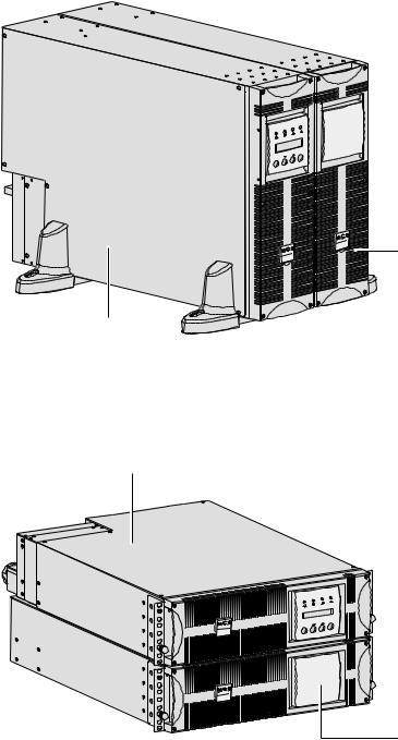
1.1 Standard configurations
Tower configuration
E X B |
R T |
|
E X |
1 |
1 |
R T |
|
|
||
|
|
|
ON |
OFF |
|
|
|
Power module
(Comet EX 5 RT / EX 7 RT / EX11 RT)
Rack configuration
Power module (Comet EX 5 RT / EX 7 RT / EX11 RT)
E X |
1 1 |
R T |
|
|
ON |
OFF |
|
|
E X B |
R T |
1. Presentation
|
Dimensions in mm/inches |
|
(H x W x D) |
Comet EX 5 RT |
444 x 131 x 635 |
Comet EX 7 RT |
17.49" x 5.16" x 25" |
Comet EX 11 RT |
|
Comet EXB 7 RT |
|
Comet EXB 11 RT |
|
|
|
|
Weight in kg/lbs |
Comet EX 5 RT |
22.5 / 49.6 |
Comet EX 7 RT |
|
Comet EX 11 RT |
27.5 / 60.6 |
Comet EXB 7 RT |
64.5 / 142 |
Comet EXB 11 RT |
68.5 / 151 |
Battery module
(Comet EXB 7 RT / EXB 11 RT)
|
Dimensions in mm/inches |
|
(H x W x D) |
Comet EX 5 RT |
131 (3U) x 444 x 635 |
Comet EX 7 RT |
5.16" (3U) x 17.49" x 25" |
Comet EX 11 RT |
|
Comet EXB 7 RT |
|
Comet EXB 11 RT |
|
|
|
|
Weight in kg/lbs |
Comet EX 5 RT |
22.5 / 49.6 |
Comet EX 7 RT |
|
|
|
Comet EX 11 RT |
27.5 / 60.6 |
Comet EXB 7 RT |
64.5 / 142 |
Comet EXB 11 RT |
68.5 / 151 |
Battery module
(Comet EXB 7 RT / EXB 11 RT)
34007724EN/AA - Page 5
1. Presentation
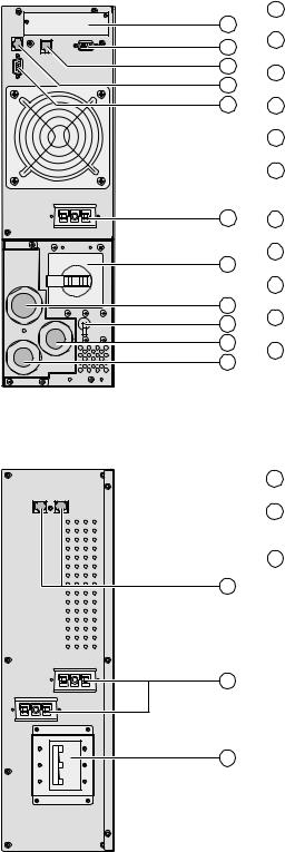
1.2 Rear panels
Power module Comet EX 5 RT / EX 7 RT / EX 11 RT
1 Slot for communication cards.
1
2 Communication port by relays.
2
3
3 Remote Emergency Power Off communication port (REPO).
4
54 Connectors for automatic detection of battery module(s).
5 RS232 communications port.
6 Battery module connectors (to the UPS or to other battery modules).
NORMAL
BY
PASS
6
7
10
9
8
11
7Manual Bypass switch.
8Output terminal block.
9Normal AC source circuit-breaker.
10Normal AC source terminal block.
11Bypass AC source terminal block.
Battery module Comet EXB 7 RT / EXB 11 RT
4 |
Connectors for automatic detection of battery module(s). |
6 |
Battery module connectors (to the UPS or to other battery |
|
modules). |
12 |
Battery circuit breaker. |
4
6
12
Page 6 - 34007724EN/AA
1. Presentation
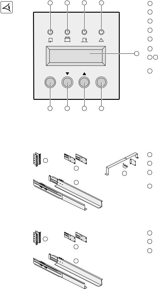
1.3 Display and control panel
13 |
14 |
15 |
16 |
13 |
Load protected LED. |
|
|
|
|
14 |
Operation on battery LED. |
E X 1 1 R T 3:1 |
|
15 |
Operation on bypass LED. |
||
|
|
|
|
||
|
|
|
|
16 |
Fault LED. |
|
|
|
|
17 |
Alphanumeric display. |
|
|
|
|
18 |
UPS OFF button. |
|
LOAD LEVEL |
|
17 |
|
|
|
4 kW / 5 kVA |
|
19 |
20 Function buttons (scroll up / scroll |
|
|
|
|
down). |
||
|
|
|
|
|
|
OFF |
|
|
ON |
21 |
UPS ON button (or function button in |
|
|
|
personalisation mode). |
||
|
|
|
|
|
|
18 |
19 |
20 |
21 |
1.4 Options
Rack mounting kits
Telescopic rails for Power module mounting in 19" enclosure with mounting hardware
(Part number 68001)
|
22 |
Ear hangup. |
22 |
23 |
|
|
Rear bracket system for transportation. |
|
23 |
|
|
25 |
24 |
Telescopic rails, 639 mm to 1005 mm |
|
|
|
|
|
length (27.36" to 39.96"). |
24 |
|
|
|
25 |
Input/Output box bracket system. |
Telescopic rails for Battery module mounting in 19" enclosure with mounting hardware
(Part number 68002)
22 Ear hangup.
22
23 Rear bracket system for transportation.
23
24 Telescopic rails, 639 mm to 1005 mm length (27.36" to 39.96").
25
34007724EN/AA - Page 7
1. Presentation
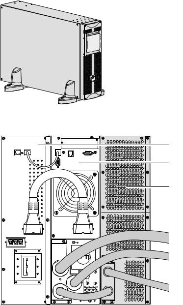
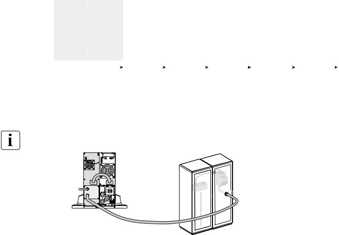
Transformer for galvanic isolation or earthing arrangement change
(Part number 68003)
This module is necessary either when a downstream neutral system from the UPS upstream is required, or when a different power source connects the automatic bypass for higher availability.
|
|
Transform |
er |
|
R T |
|
|
E X |
|
|
Example of EX RT transformer connected upstream for Comet EX RT galvanic isolation
NORMAL
BY
PASS
Battery module (Comet EXB RT)
Power module
(Comet EX 5 RT / EX 7 RT / EX 11 RT)
Transformer module (Comet EX RT)
Normal AC input
UPS output to load
Bypass AC input
Page 8 - 34007724EN/AA
1. Presentation
Battery extensions for UPS backup times up to 60 minutes (at full load)
Comet EX RT offers a standard backup time of 5/9 minutes at full load.
To increase backup time, it is possible to connect Comet EXB 7 RT / EXB 11 RT modules to the UPSs.
Battery extensions for Comet EX 5 RT, Comet EX 7 RT or Comet EX 11 RT
|
|
|
|
|
|
|
Comet |
|
|
Comet |
|
|
Comet |
|
|
Comet |
|
|
Comet |
Comet |
EX 5/7 RT |
|
|
|
|
|
|
|
|
|
|
|
|||||||
+ EXB 7 |
RT |
|
+ |
EXB 7 RT |
+ |
EXB 7 RT |
+ |
EXB 7 RT |
+ |
EXB 7 RT |
+ |
EXB 7 RT |
|||||||
|
/ |
|
/ |
/ |
/ |
/ |
/ |
||||||||||||
Comet |
EX 11 RT |
|
Comet |
Comet |
Comet |
Comet |
Comet |
||||||||||||
+ EXB 11 RT |
|
|
|
EXB 11 RT |
|
|
EXB 11 RT |
|
|
EXB 11 RT |
|
|
EXB 11 RT |
|
|
EXB 11 RT |
|||
|
|
|
|
|
|
|
|
|
|
|
|
|
|
|
|
|
|
|
|
|
|
|
|
|
|
|
|
|
|
|
|
|
|
|
|
|
|
|
|
|
|
|
|
|
|
|
|
|
|
|
|
|
|
|
|
|
|
|
|
5 kVA: |
9 min |
26 min |
42 min |
60 min |
72 min |
87 min |
7 kVA: |
7 min |
20 min |
32 min |
45 min |
57 min |
70 min |
11 kVA: |
5 min |
14 min |
22 min |
30 min |
42 min |
53 min |
CLA module (Long backup time charger) for backup times from 2 to 8 hours
(Part number 68004)
Very long backup times, from 2 to 8 hours at full load, require a Comet EX RT CLA module.
Comet |
Comet |
EX RT CLA |
EX 5 RT / |
|
EX 7 RT / |
|
EX 11 RT |
50A
~
Battery backup time |
Recommended batteries for: |
|
|
|
Comet EX5 RT |
Comet EX7 RT |
Comet EX11 RT |
|
|
|
|
2 hours |
50 Ah |
65 Ah |
100 Ah |
|
|
|
|
4 hours |
100 Ah |
130 Ah |
200 Ah |
|
|
|
|
8 hours |
200 Ah |
260 Ah |
400 Ah |
|
|
|
|
Total battery voltage : 240 V DC (20 x 12V DC).
The battery capacity must be set within the UPS (5 Ah increment possible, see UPS Personalisation section).
34007724EN/AA - Page 9
1. Presentation
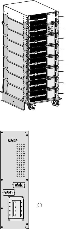
Modules integration system (Part number 68005)
Transformer module
Power module
Batteries modules
Modules integration system for extended backup time configurations to conveniently stack and secure up to 8 modules on the same cart (swivel wheels with brakes, leveling feet, seismic side panels, plates to lock modules and screws included).
Battery module with Remote Emergency Power Off function (REPO)
Part number:
EXB 7 RT EPO: 68079.
EXB 11 RT EPO: 68119.
 12 Battery circuit breaker with Remote Emergency Power OFF shunt trip.
Battery extension cable (1,8 m / 6 ft, Part number 68006)
This extended battery cable will be used instead of the standard battery cable when battery modules are distant from each other (located in two different enclosures, for instance).
Page 10 - 34007724EN/AA
2. Installation
2.1 Unpacking and parts check
Power module
E X |
1 1 |
R T |
22 |
23 |
|
|
24 |
|
|
30 |
25 |
31 |
26 |
Battery module
32
22Two sets of tower stands.
23RS232 communications cable.
24Product documentation.
25Telescopic rails for rack enclosure with mounting hardware (optional, or standard with
Network Pack version).
26Solution-Pac power management suite CDROM.
E X B |
R T |
27 |
28 |
29
24
25
27Tower stand expanders.
28Battery cable.
29Battery communication cable.
30Input/Output junction box (with 11 insulated ferrules).
31Network Management card (optional, or standard in Network Pack version).
32Bezel screw driver.
Packaging must be destroyed according to waste management standards. Recycling icons are displayed for easy selection.
A dangerous voltage is present inside the power module and the battery module. Any operations to be carried out on these modules must be done so by qualified staff.
34007724EN/AA - Page 11
2. Installation
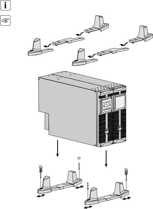
2.2 Installation in tower configuration
Use the tower stand template provided with the battery module.
2
1 |
2 |
|
1
E X B |
R T |
|
E X |
1 |
1 |
R T |
|
|
||
|
|
|
ON |
OFF |
|
|
|
3
3
 4
4
4 |
4 |
|
 4
4
Follow steps 1 to 4 to adjust the tower stands for the upright position.
Page 12 - 34007724EN/AA
 Loading...