


www.mgeups.com |
MGE UPS SYSTEMS,INC. |
|
Pulsar EX
2200RT / 3200RT EXB 2200/3200 RT
Installation and User
Manual
Introduction
Important safety instructions
Read before installing product
SAVE THESE INSTRUCTIONS. This manual contains important instructions that should be followed during installation and maintenance of the UPS and batteries.
Thank you for selecting an MGE UPS SYSTEMS, Inc. product to protect your electrical equipment.
The Pulsar EX RT range has been designed with the utmost care.
We recommend that you take the time to read this manual to take full advantage of your UPS’s many fratures.
MGE UPS SYSTEMS, Inc. pays great attention to the environmental impact of its products.
Measures that have made Pulsar EX RT a reference in environmental protection include:
The eco-design approach used in product development,
Recycling of Pulsar EX RT at the end of its service life.
To discover the entire range of MGE UPS SYSTEMS, Inc. products and the options available for the Pulsar EX RT range, we invite you to visit our web site at www.mgeups.com or contact your MGE UPS SYSTEMS, Inc. representative.
This manual contains important instructions for Pulsar EX RT Models that must be followed during installation, operation and maintenance of the UPS and batteries.
The Pulsar EX RT Models that are covered in this manual are listed below.
Pulsar EX 2200RT, Pulsar EX 3200RT.
The normal battery voltage for all models is as follows:
Pulsar EXB 2200/3200 RT: 72 Vdc.
The Pulsar UPS is intended for installation in a temperature within 0 to 40º C, free of conductive contaminant.
This equipment has been tested and found to comply with the limits for a Class A digital device, pursuant to Part 15 of the FCC Rules. These limits are designed to provide reasonable protection against harmful interference when the equipment is operated in a commercial environment. This equipment generates, uses, and can radiate radio frequency energy and, if not installed and used in accordance with the instruction manual, may cause harmful interference to radio communications. Operation of this equipment in a residential area is likely to cause harmful interference in which case the user will be required to correct the interference at his own expense.
Page 2 - 3400753300/AE
Introduction
CAUTION: Safety of persons
The UPS has its own internal power source (the battery). Consequently, the power outlets may be energized even if the UPS is disconnected from the AC-power source.
Dangerous voltage levels are present within the UPS. It should be opened exclusively by qualified service personnel.
The UPS must be properly earthed. Measurements are required to ensure that the total leakage current of the UPS and the protected equipment does not exceed 3.5 mA by checking their characteristics (maximum leakage current of the UPS = 2 mA).
The battery supplied with the UPS contains small amounts of toxic materials. To avoid accidents, the directives listed below must be observed:
-Never burn the battery (risk of explosion).
-Do not attempt to open the battery (the electrolyte is dangerous for the eyes and skin).
-Comply with all applicable regulations for the disposal of the battery.
-Batteries constitute a danger (electrical shock, burns). The short-circuit current may be very high. Precautions must be taken for all handling: remove watches, rings, bracelets and any other metal objects, use tools with insulated handles.
-Do not lay tools or metal parts on top of batteries.
CAUTION: Product Safety
The UPS connection instructions and operation described in the manual must be followed in the indicated order.
UPS must be connected to a nearby wall outlet that is easily accessible. The UPS can be disconnected from the AC-power source by removing the power cord.
Check that the indications on the rating plate correspond to your AC-power system and to the actual electrical consumption of all the equipment to be connected to the UPS.
Never install the UPS near liquids or in an excessively damp environment.
Never let a foreign body penetrate inside the UPS.
Never block the ventilation grates of the UPS.
Never expose the UPS to direct sunlight or source of heat.
If the UPS must be stored prior to installation, storage must be in a dry place.
The admissible storage temperature range is -25ºC to +55ºC.
Special Precautions
All handling operations will require at least two people (unpacking, installation in rack system).
Once installed and connected to the AC power source for the first time, the battery will start to charge. Full charging to obtain the rated battery backup time requires at least 8 hours.
Before and after the installation, if the UPS remains de-energized for a long period, the UPS must be energized for a period of 24 hours, at least once every 6 months (for a normal storage temperature less than 25°C). This charges the battery, thus avoiding possible irreversible damage. During the replacement of the battery module, it is imperative to use the same type and number of element previously mounted in the UPS, in order to maintain an identical level of performance and safety. In case of doubt, don’t hesitate to contact our after sales department (for more information, refer to the web site www.mgeups.com).
3400753300/AE - Page 3

How to use this document
Using this document
Information may be found primarily by consulting:
The contents,The index.
Icon Usage
WARNING: Eminent hazard to personnel or equipment, information must always be followed.
CAUTION: Hazard to personnel or equipment, information that must always be followed.
Notes, tips and information, help.
Important information, help.
Visual indication.
Action.
Audio indication.
In the illustrations on the following pages, the symbols below are used:
LED off.
LED on.
LED flashing.
Page 4 - 3400753300/AE
Contents
1.Presentation
1.1 |
System configurations ................................................................................................................ |
7 |
|
Rack setup ...................................................................................................................................... |
7 |
|
Tower setup .................................................................................................................................... |
7 |
1.2 |
Rear panel ...................................................................................................................................... |
8 |
|
Pulsar EX 2200RT ........................................................................................................................ |
8 |
|
Pulsar EX 3200RT ........................................................................................................................ |
8 |
|
Pulsar EXB 2200/3200 RT ............................................................................................................ |
8 |
1.3 |
Control panel ................................................................................................................................ |
9 |
2.Installation
2.1 |
Unpacking .................................................................................................................................... |
10 |
2.2 |
Installation in rack position ........................................................................................................ |
11 |
2.3 |
Installation in tower position .................................................................................................... |
12 |
2.4 |
Connection to the RS232 or USB communication port (optional) ........................................ |
13 |
2.5 |
Installation of the communication-card option ........................................................................ |
13 |
2.6 |
Connections ................................................................................................................................ |
14 |
3.Operation
3.1 |
Start-up ........................................................................................................................................ |
15 |
3.2 |
LED indicators ............................................................................................................................ |
15 |
3.3 |
Operation on battery power (following failure of AC input power) ............................................ |
16 |
|
Transfer to battery power .............................................................................................................. |
16 |
|
Threshold for the low-battery warning............................................................................................ |
16 |
|
End of backup time ........................................................................................................................ |
16 |
3.4 |
Personalization (optional) ............................................................................................................ |
17 |
|
Function.......................................................................................................................................... |
17 |
|
"ON / OFF conditions" tab.............................................................................................................. |
17 |
|
"Battery" tab .................................................................................................................................. |
17 |
|
"Output" tab.................................................................................................................................... |
18 |
|
"Bypass" tab .................................................................................................................................. |
18 |
3.5 |
UPS Shutdown ............................................................................................................................ |
18 |
3.6 |
UPS Remote Power Off .............................................................................................................. |
19 |
3400753300/AE - Page 5
Contents
4.Maintenance
4.1 |
Troubleshooting .......................................................................................................................... |
20 |
4.2 |
Replacement of the battery modules ........................................................................................ |
22 |
5. Environment .................................................................................................................................... |
24 |
|
6.Appendices
6.1 |
Technical characteristics |
..........................................................................................................25 |
6.2 |
Glossary ...................................................................................................................................... |
26 |
6.3 |
Index ............................................................................................................................................ |
27 |
Page 6 - 3400753300/AE

1.1 System configurations
Rack setup
17.24 inches (19" Rack mount)
P U L S A R
E X
www.mgeups.com
1. Presentation
25.75 inches (EX 2200RT)
26.00 inches (EX 3200RT)
3.75 inches
(2U)
2 |
1 |
Tower setup
Model |
Part |
Weight |
|
Number |
(Ibs/kg) |
Pulsar EX 2200RT |
85220 |
80.8 lbs (36.6 kg) |
Pulsar EX 3200RT |
85320 |
82.7 lbs (37.5 kg) |
Pulsar EXB 2200/3200 RT |
85000 |
92.8 Ibs (42.0 kg) |
1
2
P U L S A R
E X
www.mgeups.com
3400753300/AE - Page 7

1. Presentation
1.2 Rear panel
Pulsar EX 2200RT
1Slot for communication-card option.
3 |
8 |
9 |
10 |
11 |
12 |
4 |
|
5 |
1 |
2 |
RS232 communication port. |
|
|
|
|
|
|
|
|
|
|
||
|
|
|
|
|
|
|
|
|
|
3 |
USB communication port. |
|
|
|
|
|
|
|
|
|
|
4 |
Upper two receptacles for connection |
|
|
|
|
|
|
|
|
|
|
|
to AC-power source. |
|
|
|
|
|
|
|
|
|
|
5 |
Lower two programmable receptacles |
|
|
|
|
|
|
|
|
|
|
|
(1 and 2). |
|
L5-20P Plug |
|
|
|
|
|
|
|
|
6 |
Output circuit breakers. (EX 3200RT) |
|
|
|
|
|
|
|
|
|
|
||
2 |
INPUT CABLE |
|
|
|
|
L5-20R Receptacle |
|
|
|||
|
|
|
|
|
|
|
|||||
|
7 |
|
|
|
|
OUTPUT CABLE |
|
Input/Output power cords for direct |
|||
|
|
|
|
|
|
7 |
|||||
|
|
|
|
|
|
|
|
|
|
||
Pulsar EX 3200RT |
|
|
|
|
|
|
|
|
|
|
connection of protected equipment. |
|
|
|
|
|
|
|
|
|
|
EX 2200RT-L5-20P/L5-20R; and |
|
3 |
8 |
9 |
10 |
11 |
12 |
6 |
4 |
5 |
1 |
|
EX 3200RT-L5-30P/L5-30R. |
|
|
||||||||||
|
|
|
|
|
|
|
|
|
|
8 |
Connector for an additional battery |
|
|
|
|
|
|
|
|
|
|
|
module. |
|
|
|
|
|
|
|
|
|
|
9 |
Connector for automatic detection of an |
|
|
|
|
|
|
|
|
|
|
|
additional battery module. |
|
|
|
|
|
|
|
|
|
|
10 |
Pushbutton to test phase/neutral |
|
|
|
|
|
|
|
|
|
|
|
inversion of AC-power source. |
|
L5-30P (Plug) |
|
|
|
|
|
|
|
|
11 |
LED indicating Site Wiring Alarm |
|
|
|
|
|
|
|
|
|
|
Enable, with flashing and intermittent |
|
2 |
INPUT CABLE |
|
|
|
|
L5-30R (Receptacle) |
|
||||
|
|
|
|
|
buzzer. Reset fault with rear panel |
||||||
|
|
|
|
|
|
|
|||||
|
|
|
|
|
|
|
OUTPUT CABLE |
|
|||
|
|
7 |
|
|
|
|
|
button. |
|||
|
|
|
|
|
|
|
|
|
|
||
Pulsar EXB 2200/3200 RT
14 15
13 |
13 |
12Connector for remote power off (RPO).
13Battery module connectors (to the UPS or to other battery modules).
14Connectors for automatic detection of additional battery modules.
15Circuit breaker for battery ON/OFF and protection.
Page 8 - 3400753300/AE
1. Presentation
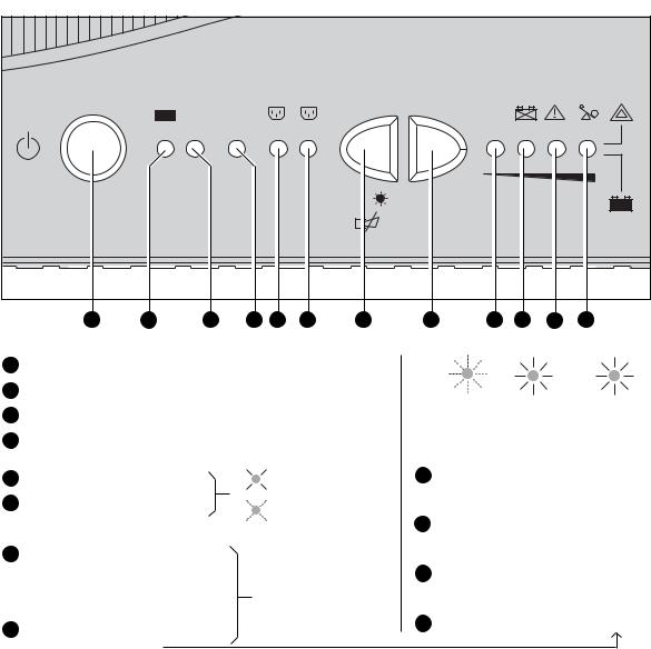
1.3 Control panel
BYPASS 2 1
test |
% |
100% |
% |
|
20% 50% 80% |
16 |
17 |
18 |
19 |
20 |
21 |
22 |
16ON / OFF.
17Operation on battery power.
18Operation in ON-LINE mode (backup power available).
19Operation on bypass (no backup power available).
20 Status of programmable outlet 2:
21Status of programmable outlet 1:
22Lamp test or buzzer OFF.
Forced transfer to bypass and back by pressing button 3 times in less than 5 seconds.
23Hold down to display percent load:
Supplied with power
Status change in progress.
Press simultaneously at least 3 seconds to reset the “End of battery life” alarm.
23 |
24 |
25 |
26 |
27 |
|
|
% |
% |
|
|
Alarms |
battery |
load |
|
|
|
remaining |
|
|
27 |
UPS |
100% |
100% |
|
|
overload |
|
|
|
26 |
Electronics |
80% |
80% |
|
|
fault |
|
|
|
25 |
Battery |
50% |
50% |
|
fault * |
||||
24 |
Site Wiring |
20% |
20% |
|
Fault |
||||
|
|
(*): flashing LED + buzzer: battery fault (battery must be replaced).
flashing LED + long buzzer (once per hour): theoretical end of battery life (replacement recommended).
3400753300/AE - Page 9
 Loading...