


 Loading...
NIRS
XDS MultiVial Analyzer
Manual
8.921.8002EN / 2013-12-19

Metrohm AG CH-9100 Herisau Switzerland
Phone +41 71 353 85 85 Fax +41 71 353 89 01 info@metrohm.com www.metrohm.com
NIRS
XDS MultiVial Analyzer
Manual
8.921.8002EN / 2013-12-19 |
fpe |
Teachware
Metrohm AG CH-9100 Herisau
teachware@metrohm.com
This documentation is protected by copyright. All rights reserved.
Although all the information given in this documentation has been checked with great care, errors cannot be entirely excluded. Should you notice any mistakes please send us your comments using the address given above.
Table of contents
1 |
Introduction ................................................................................................................... |
5 |
|
2 |
Site Readiness ................................................................................................................ |
8 |
|
|
2.1 |
Temperature and Humidity........................................................................... |
8 |
|
2.2 |
General Environment .................................................................................... |
8 |
|
2.3 |
Vibration....................................................................................................... |
8 |
|
2.4 |
Electrical Power ............................................................................................ |
8 |
|
2.5 |
Instrument Communication .......................................................................... |
8 |
|
2.6 |
Instrument Dimensions and Weight.............................................................. |
9 |
3 |
XDS Instrument Connection ......................................................................................... |
10 |
|
|
3.1 |
Network Connection, connected to an active network port as shown........ |
10 |
3.2Direct Connection, in a free-standing manner with no network connection 11
|
3.3 |
Overview of XDS Instrument Communication ............................................. |
11 |
|
3.4 |
Flowchart Diagram of XDS communication protocol .................................. |
12 |
|
3.4.1 |
Microsoft Windows Firewalls ................................................................................ |
13 |
|
3.4.2 |
Network Evolution Issues ...................................................................................... |
13 |
|
3.4.3 |
Quick Glossary of Terms:....................................................................................... |
13 |
|
3.5 |
Connection in Vision ................................................................................... |
14 |
|
3.6 |
Troubleshooting Connection Problems ....................................................... |
15 |
|
3.6.1 |
Network Troubleshooting Overview...................................................................... |
16 |
|
3.6.2 |
Direct Connection Troubleshooting Overview........................................................ |
20 |
4 Assembly of the Instrument ......................................................................................... |
22 |
||
5 |
XDS MultiVial Module .................................................................................................. |
27 |
|
|
5.1 |
Introduction to Vial Analysis....................................................................... |
27 |
|
5.2 |
Creation of a Custom Vial Size.................................................................... |
28 |
|
5.3 |
Spot Size Adjustment.................................................................................. |
30 |
|
5.4 |
Iris Adapter................................................................................................. |
33 |
|
5.4.1 |
Installation of Iris Adapter:.................................................................................... |
33 |
|
5.5 |
Use of the Sample Transport Mechanism.................................................... |
35 |
|
5.5.1 |
Use of the Iris Adapter: ......................................................................................... |
36 |
6 Vision Software: Connection to the Instrument............................................................ |
37 |
||
|
6.1 |
Entry into Vision ......................................................................................... |
37 |
|
6.2 |
Use of Vial Dialog Selection Menu .............................................................. |
43 |
|
6.2.1 |
Sample ID Entry .................................................................................................... |
45 |
|
6.2.2 |
Order of Sampling ................................................................................................ |
51 |
|
6.2.3 |
Additional Vial Dialog Functions............................................................................ |
53 |
7 |
Instrument Diagnostics................................................................................................. |
57 |
|
|
7.1 |
Setup Diagnostics ....................................................................................... |
57 |
|
7.1.1 |
Wavelength Linearization...................................................................................... |
58 |
|
7.1.2 |
Reference Standardization, “Use Tray” Position..................................................... |
60 |
|
7.1.3 |
Reference Standardization, “Use Iris” Position ....................................................... |
64 |
▪▪▪▪▪▪▪ 3
|
7.1.4 |
Instrument Calibration .......................................................................................... |
68 |
|
7.1.5 |
IPV Setup (Instrument Performance Verification) ................................................... |
71 |
|
7.2 |
Evaluation Diagnostics ............................................................................... |
73 |
|
7.2.1 |
Performance Test ................................................................................................. |
74 |
|
7.2.2 |
Wavelength Certification ...................................................................................... |
77 |
|
7.2.3 |
Photometric Test .................................................................................................. |
81 |
|
7.2.4 |
Gain Test.............................................................................................................. |
85 |
|
7.2.5 |
7.2.5 Low Flux Test .............................................................................................. |
86 |
8 |
Instrument Maintenance.............................................................................................. |
89 |
|
|
8.1 |
Overview.................................................................................................... |
89 |
|
8.2 |
Fan Filter Replacement............................................................................... |
90 |
|
8.3 |
Lamp Replacement..................................................................................... |
91 |
|
8.4 |
Fuse Replacement ...................................................................................... |
97 |
|
8.5 |
Maintenance Log ....................................................................................... |
99 |
|
8.6 |
Window Cleaning..................................................................................... |
100 |
9 |
Validation Tools......................................................................................................... |
102 |
|
|
9.1 |
Hardware Validation Tools....................................................................... |
103 |
|
9.1.1 |
Factory Instrument Test Guide and Results.......................................................... |
103 |
|
9.1.2 |
Installation and Operating Qualification Documents............................................ |
103 |
|
9.1.3 |
NIRStandards® for Instrument Performance Verification..................................... |
103 |
|
9.1.4 |
Instrument Performance Certification.................................................................. |
103 |
|
9.1.5 |
Metrohm NIRSystems Master Instrument Program.............................................. |
104 |
|
9.2 |
Software Validation Tools........................................................................ |
104 |
|
9.2.1 |
Installation and Operating Qualification Documents............................................ |
104 |
|
9.2.2 |
Vision Certificate of Validation............................................................................ |
104 |
|
9.2.3 |
21 CFR Part 11 Compliance ................................................................................ |
105 |
10 |
|
Safety and Electrical Certification............................................................. |
107 |
11 |
|
Troubleshooting....................................................................................... |
108 |
12 |
|
Lifting and transporting the Metrohm instrument: .................................. |
112 |
|
12.1 |
Instructions for MultiVial® Shipping Position........................................... |
113 |
|
12.1.1 |
Instructions follow.............................................................................................. |
113 |
13 |
|
Index........................................................................................................ |
115 |
4 ▪▪▪▪▪▪▪

1 Introduction
Thank you for selecting the XDS MultiVial Analyzer, manufactured by FOSS. This instrument is the third generation in a series of instruments designed for precision NIR measurement, characterization of organic materials, and qualification of known materials to allowable quality parameters.
The XDS MultiVial Analyzer is designed for stable operation in typical laboratory environments, while providing the precision and accuracy users have come to expect of FOSS near-infrared (NIR) instruments.
The MultiVial Analyzer comes with a choice of one vial tray. Others are optional.
The MultiVial Analyzer uses a proven monochromator design, employing a digitally-controlled dispersive grating, sensitive detection devices, and state-of-the-art circuitry to enhance signal output and minimize any extraneous noise that might influence performance. The XDS MultiVial Analyzer uses various patented algorithms to provide superior accuracy and transferability between like instruments. These software algorithms must be used to assure method transfer between instruments. See section 7.1 for full details.
The versatile sampling mechanism of the MultiVial Analyzer offers a movable sampling platform, suitable for handling multiple vials or other samples. The software supports acquisition of spectra in an unattended mode, freeing the operator to prepare other samples, analyze data, or perform unrelated tasks.
Vision supports four different default vial diameters, to speed set-up. For custom vial diameters, set-up is straightforward. The MultiVial Analyzer also offers variable spot size, to focus energy on small vials.
Horizontal orientation of the sample transport mechanism facilitates loading, and prevents material spills inside the sampling area of the instrument. The MultiVial Analyzer supports use of normal sampling accessories for the XDS Rapid Solids Analyzer.
Sampling may be performed on two different physical levels, either directly on the sample window (as with a normal XDS RCA) or on the vial tray, which is slightly raised from the glass. For this reason,
▪▪▪▪▪▪▪ 5
two sets of optical (“reference”) calibrations are stored in the instrument. It is important to Reference Standardize on the correct level, as prompted by Vision Software. This aids in method transfer, and is explained in the section on Reference Standardization.
This instrument uses near-infrared (NIR) spectral energy to illuminate the sample. By measuring the energy reflected off (or passing through) the sample, chemical information and composition may be determined. This information may be used for quantification of constituents, or for comparison to a library of known materials, providing identification and qualification of materials.
Vision Software™ offers an easy user interface, using the familiar interface provided with previous generations of NIR instrumentation. All functions required to perform identification, qualification, and quantitation are provided, with easy tools for interpretation of results. Vision offers full instrument diagnostics, with built-in acceptance specification tables for all tests. Vision stores all results in a diagnostic database for later lookup, with control chart views of results tracked over time.
The menu-driven, validated Vision Software package meets all requirements of CFR 21 Part 11, covering Electronic Records and Signatures. Vision comes with a full manual for operation and theory of operation, with complete instructions for analytical development.
The XDS Analyzer provides 0.5nm data points, and uses several innovative methods to assure wavelength accuracy and repeatability. Wavelength positions are traceable to NIST SRM-1920. Because SRM-1920 does not have certified wavelengths above 2000 nm, an additional wavelength absorber is included in the calibration standard, to provide stable wavelengths beyond 2000 nm. These additional wavelengths have been independently measured on calibrated instrumentation to ascertain the wavelength positions used.
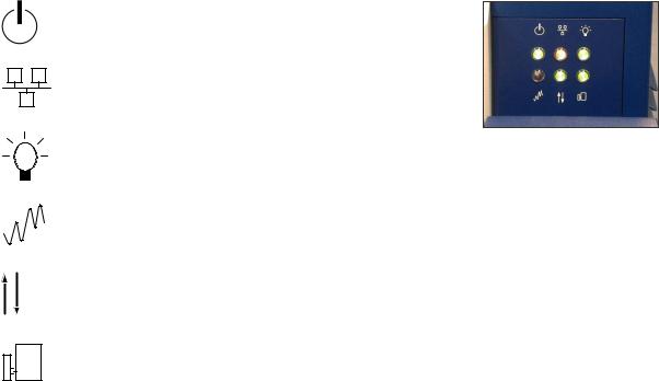
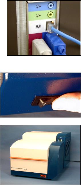
A panel of 6 LED indicators provides information to the user on these functions:
Icon Status
Green when power is ON
Amber when connected to network or direct connection
Green when instrument lamp is ON
Red when scanning reference or sample
Green when stable operating temperature is reached
Green when module is properly attached
Instrument communication uses RJ-45 network connections, to eliminate issues involved with long runs of RS-232 cable. An Internet Protocol (IP) address is dynamically requested upon connection.
6 ▪▪▪▪▪▪▪
This IP address may be permanently installed, if required for network purposes. RJ-45 connection also permits remote interrogation and diagnostics checks of the instrument, if necessary and authorized.
The instrument enclosure is completely sealed to prevent contamination by dust or other substances. The cooling fans operate outside the main enclosure, and are thermally linked to internal fans that maintain a constant temperature inside the instrument enclosure. There is no airflow drawn into the optics chamber instrument. An external fan-cooling loop is provided in the side chassis, with thermal conduction from the inside of the optics chamber. This avoids contamination of the instrument in dusty environments. An air filter is built into the door of this chamber. For cool environments, heaters are embedded in the thermal transfer block to raise temperature when required.
Lamp changes are performed through a single panel on the rear surface of the instrument. The lamp is easy to remove and replace, and requires no special tools or expertise.
▪▪▪▪▪▪▪ 7
2 Site Readiness
Like most precision instruments, the MultiVial Analyzer (RCA) is sensitive to environmental conditions that can affect its performance and useful life. Observe the following guidelines when selecting a site and installing the instrument:
2.1 Temperature and Humidity
The XDS Analyzer is designed to work in ambient air temperatures from 40-95°F (4.5-35°C).
Use the XDS Analyzer only in 10-90% relative humidity levels, non-condensing. Rapid changes in humidity can cause interferences by adding trace moisture absorptions to the spectra. In general, lower humidity levels are preferred.
The Performance Test (a comprehensive instrument diagnostic test in Vision software) is somewhat sensitive to changes in ambient humidity, and the Performance Test may fail under conditions of extreme humidity, or rapidly varying humidity.
2.2 General Environment
Minimize exposure of the monochromator to dust.
Inspect the fan filter at least monthly. If an accumulation of lint, dust, or other matter has accumulated, pull open the right-hand panel from the instrument. Replace the filter. If dust has accumulated on the fans, carefully wipe them clean with a moist soft cloth. Do not distort or damage the fan blades or fins, as this will impede cooling.
Do not place the instrument directly near any HVAC duct. The direct flow of heating or cooling air will cause the instrument to exhibit high noise during the Performance Test.
2.3 Vibration
Install the XDS Analyzer where it will not be affected by bench vibration from grinders, blenders, stirrers, or mixers.
Never permit hammering or other physical impact on the bench top supporting the XDS Analyzer or its computer.
2.4 Electrical Power
Power should be a single, separate, stable, transient-free filtered AC circuit. The circuit should have surge protection.
Operating voltage for the instrument is 100-240VAC, 50/60Hz. The power supply is self-switching and will provide the correct operating voltage to the instrument.
Maximum power consumption is 750W.
2.5 Instrument Communication
The XDS MultiVial Analyzer can communicate directly with the computer by use of a UTP Crossover Cable (gray cable) supplied with unit.
Alternatively, the instrument may be accessed directly through a network connection. This uses a standard RJ-45 type cable, such as CDW #074092, available from CDW Computer Centers, Inc. The
8 ▪▪▪▪▪▪▪
instrument detects network capability and optimizes communication speed.
The computer that operates the instrument must have clear access through the network, and be configured to communicate properly. This communication is the responsibility of your on-site network personnel.
Full instructions are given in section 3.0.
2.6 Instrument Dimensions and Weight
The XDS MultiVial Analyzer dimensions are:
• |
Width: |
18.0” |
(457 mm) |
• |
Height |
15.25” (387 mm) |
|
• |
Depth |
22.5” |
(572 mm) front to back |
Leave a minimum of 3” (76mm) around the instrument sides and back for airflow and access space. Leave as much space as possible in front for sample handling.
• Weight |
68.7 pounds (31.25 kg) |
Follow lifting instructions (on last page) when moving the instrument. Avoid injury.
▪▪▪▪▪▪▪ 9
3 XDS Instrument Connection
The XDS instrument may be connected to the host computer in one of two ways: If the XDS Instrument will be used as part of a network, use the Network Connection method shown immediately below. If there are not enough active network ports near the XDS instrument, a hub or router may be used.
This section assumes use of Windows® 2000, XP, or later versions of Windows Operating Systems. For computers using Windows 95, 98, or NT 4.0, we recommend upgrade of the computer and operating system to current specifications.
CAUTION: METROHM NIRSystems does not recommend the use of two network cards under any circumstances. Do not use Direct Connection to the instrument along with a network connection to the company network. The use of two network cards -- on one data bus in the computer – may result in lost commands, lost data, and unsatisfactory software operation. Metrohm cannot be responsible for software and instrument problems resulting from the use of two network cards in the host computer.
This information is correct as of the time of original publication. Changes to computers, operating systems, and network protocols may require revision of this information without notice.
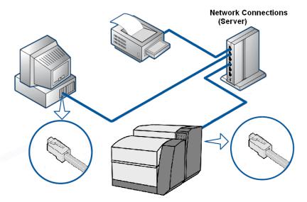
3.1Network Connection, connected to an active network port as shown
This is the preferred method of instrument communication when a connection to the company Local Area Network (LAN) is necessary. Specific information about this method follows:
•The XDS instrument should be connected -- with a “patch” cable – to the network port.
•Upon power-up, the XDS instrument will request a dynamic IP address from the network server. This is normally assigned in 5 to 10 seconds.
•The XDS instrument uses a proprietary, encrypted command language. It cannot be activated by any program except Vision, or Metrohm programs designed to operate the instrument. Therefore, the instrument maintains “Closed System” status under 21 CFR Part 11 rules. No hacking or support of viruses is possible with XDS instruments.
10 ▪▪▪▪▪▪▪
•The XDS instrument appears just like a network printer (or other peripheral device) on the LAN system. It generates no signals, and only responds when commanded by an authorized user, logged into Vision software.
•This is the easiest connection method for XDS instruments.
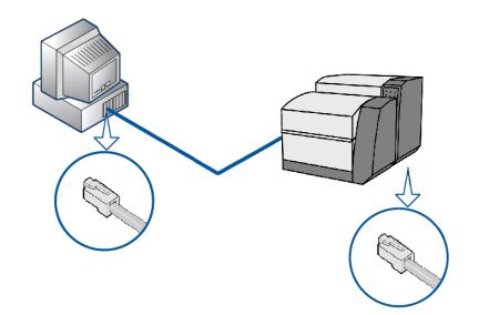
3.2 Direct Connection (without network)
This method allows users to connect to the instrument when there is no network present. In such cases, a “crossover cable” (provided) is used. The XDS instrument, upon power-up, requests a dynamic IP address. When none is supplied within 45 seconds, the XDS instrument concludes that no DHCP server is available. It then defaults to an internal IP address which the computer may use for “direct communication”.
This method of hookup should not be used when the computer is also connected to a network. Such connection may result in lost commands, lost data, and unsatisfactory software operation. Metrohm cannot be responsible for software and instrument problems resulting from the use of two network cards in the host computer.
For IT personnel, it may be helpful to understand the sequence of events used by the XDS instrument and Vision software when establishing an electronic connection. These are explained.
3.3 Overview of XDS Instrument Communication
The XDS instrument may be connected to LAN systems in the same manner as any printer or other peripheral Ethernet-enabled device. These key items will help understand the communication methods. See the flowchart diagram on next page.
1.The XDS instrument maintains “Closed System Status” under 21 CFR Part 11 guidelines. It uses a proprietary, encrypted command language. It is not susceptible to hacking or virus attacks.
2.The XDS system may only be addressed using proprietary software (usually “Vision”) which can only be entered by an authorized user, using the “two-token” method of entry. (Unique User ID and password)
3.Upon being powered up on a LAN, the XDS instrument requests a “dynamic” IP address from
▪▪▪▪▪▪▪ 11
the DHCP server which controls the LAN. This IP address is normally granted promptly (typically in 5-10 seconds) so the instrument can function on the LAN. Most DHCP servers track the XDS instrument by the “MAC” (Machine Access Code) to later re-assign that same IP address whenever the XDS instrument is on the LAN.
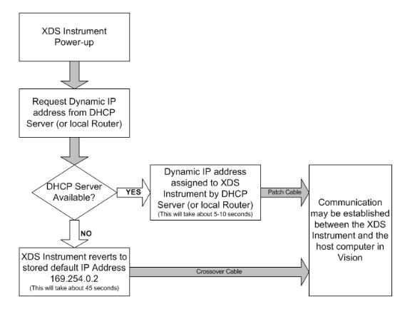
4.If there is no DHCP server available to assign an IP address (a free-standing router may serve the same DHCP function), the XDS instrument will “time out” in 45 seconds --and it will know that it is not attached to an active LAN. It will then default to an internally-stored default IP address. This address, 169.254.0.2, is used for local, free-standing communication only. In such cases, a crossover cable, or a hub with two patch cables, should be used to connect the computer and the XDS instrument.
5.Upon the next power-down and subsequent power-up of the XDS instrument, it will again request an IP address of the DHCP server. It will go through the same cycle, eventually reverting to the stored default IP address. This is intentional.
6.A dynamic IP address is the preferred method of XDS instrument connection. The default IP address is only used when no DHCP server is available to assign a dynamic IP address.
A short glossary of terms follows. See the flowchart diagram for XDS instrument communication which visually outlines the items explained above.
3.4 Flowchart Diagram of XDS communication protocol
12 ▪▪▪▪▪▪▪
3.4.1Microsoft Windows Firewalls
The Microsoft Windows® Firewall on the PC may interfere with Vision communication. To assure communication, follow these steps:
•Enter Control Panel, Security Center.
•On the “General” Tab, be sure that “exceptions” are allowed. (Un-click “Don’t allow exceptions”.)
•On the “Exceptions” Tab, click “Add Program”.
•Select Vision from the list of programs – click on it. (Vision must be installed to appear on the list.)
•Click on “OK” at each window to exit Control Panel.
3.4.2Network Evolution Issues
This document is as correct as possible at the time or writing. However, network management is an evolving discipline, and conditions will change. Some of the drivers for change include network security, authentication, and data integrity. Technology changes factor into all of these issues.
Because the network communication environment is complex and ever-changing, we have tried to provide the basic information needed for connection of the XDS instrument. 95% of users will have no connection problems, if these instructions are followed.
In the rest of the cases, there may be network issues, corporate restrictions, or other issues which inhibit easy connection. The troubleshooting section covers some of the most common problems.
In all cases, we recommend minimal tampering with computer settings. This can cause instability, and may be prohibited by company policies.
At this time, we recommend Microsoft Windows® XP as the easiest operating system by which to establish network communication. We strongly recommend that Windows 95, 98, and NT 4.0 be avoided, as they require considerable expertise in network configuration.
3.4.3Quick Glossary of Terms:
DHCP:
The Dynamic Host Configuration Protocol (DHCP) is an Internet protocol for automating the configuration of computers that use TCP/IP.
DNS Server:
A Domain Name Server. DNS Servers run special-purpose software, as part of the Domain Name System, for managing enterprise networks.
IP:
An Internet Protocol (IP) address is a numerical identification and logical address that is assigned to devices participating in a computer network utilizing the Internet Protocol for communication between its nodes.
IPv4:
IPv4 refers to “Internet Protocol version 4” which is the fourth revision in the development of the
▪▪▪▪▪▪▪ 13

Internet Protocol (IP) and it is the first version of the protocol to be widely deployed. Together with IPv6, it is at the core of standards-based internetworking methods of the Internet and is still by far the most widely deployed Internet Layer protocol. XDS Instruments use IPv4.
LAN:
A local area network (LAN) is a computer network covering a small physical area, like a home, office, or small group of buildings, such as a corporate site, a university, or an airport. These are often called “enterprises”.
Subnet Mask:
“Subnetting” is used to break a large network into smaller sections. This can enhance efficiency, raise speeds, and reduce “packet collisions” within the network. To accomplish subnetting, “Subnet Masks” may be applied to separate one section of the network from another. A subnet mask typically takes the form “255.255.255.0” or something similar. This scheme is becoming obsolete, as new network management methods are being implemented.
TCP/IP:
(Transmission Control Protocol/Internet Protocol) is the basic communication language or protocol of the Internet.
3.5Connection in Vision
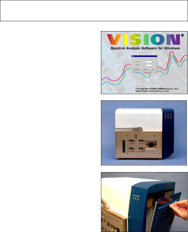
1.Log into Vision with your User ID and Password.
Click on Configure, Input as shown.
14 ▪▪▪▪▪▪▪
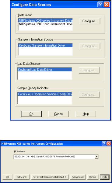
2.Highlight “NIRSystems XDSseries Instrument Driver” as shown, then click on “Configure”.
Information:
At this point, Vision requests any XDS instrument on the local area network (LAN) to report connection status. This may take a few moments.
If the instrument is not on a LAN, and instead is connected with a crossover cable, this will take a minute or more. Vision first requests a dynamic IP address, If no server or router is available to assign an IP address, Vision waits 45 seconds, then searches for the default instrument IP address, in the event of Direct Connection using a crossover cable.
3.When Vision “finds” the instrument on the LAN, it will be shown. The dynamic IP address (assigned by the server) is shown, along with the XDS Serial number. The instrument is shown as “Available” on port 2083.
Highlight the instrument and click “OK”.
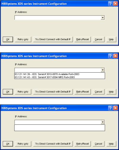
4.If the IP Address field is empty, the user should consult “Troubleshooting Connection Problems”.
3.6Troubleshooting Connection Problems
Many connection problems are easily solved, especially with Windows® XP operating systems. Windows XP is currently the preferred operating system, and has enhanced connectivity over other operating systems. Vista is good also, but may impose user security restrictions. Windows 2000 is almost as simple, but may require an extra step or two, as discussed.
▪▪▪▪▪▪▪ 15
If your computer uses Windows 95, 98, or NT 4.0 for the operating system, we strongly recommend upgrade to Windows XP for easiest connectivity. This may require a full computer upgrade, as older computers may not have the processor speed, memory, or connectivity required to run Windows XP with full Ethernet compatibility.
1.Vision cannot see any instrument on the connection path. Click on the “down arrow” at the right side of the empty field to see if instrument(s) are shown.
Solution: By expanding the field, Vision can display the instruments shown.
Note that only the top instrument, Serial #30100878, is “Available”. Highlight it and click “OK”.
2.Vision still sees no instrument(s) after expanding the field. This indicates connection or network issues.
Verify Cable Type:
Verify correct cable type for hookup. Most networks use “patch” cables. Free-standing systems use a “crossover cable”. Power down the XDS instrument, then power it back up. Wait 120 seconds for the XDS instrument to fully reset its communication. If an instrument is shown, proceed to “Acquire”, “Connect” in Vision.
If this does not resolve the problem, continue to the next section.
3.6.1Network Troubleshooting Overview
If no XDS instrument shows as “available”, there may be a setting which should be changed. It may be necessary to contact your IT department for assistance with these issues.
First, verify that the network has a DHCP Server. If no DHCP server is available, the instrument must be connected by Direct connection, using a crossover cable. If this is the case, proceed to the section entitled “Direct Connection Troubleshooting Overview”.
Network Solution 1:
16 ▪▪▪▪▪▪▪
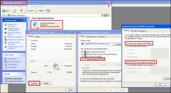
Check Internet Protocol (TCP/IP) Properties. (You may need to contact your IT department to follow these steps.)
•Click on Start, then Control Panel
•Double-click on Network Connections
•Double-click on Local Area Connection
•Click on Local Area Connection Properties
•Click on Internet Protocol (TCP/IP)
•Click on Properties
The full path, from Network Properties forward to Internet Protocol (TCP/IP) Properties, is shown:
▪▪▪▪▪▪▪ 17
Verify these settings:
•Obtain an IP address automatically
•Obtain DNS server address automatically
When finished, click “OK”. Close all other boxes opened for this verification.
If the settings were not set properly, it may be necessary to exit Windows XP, then re-enter XP, to have the correct settings take effect. If in doubt, do this and try XDS instrument communications again after this takes effect.
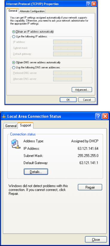
Network Solution 2:
Returning to the Local Area Connection Status dialog box, note these items for the computer:
•Address Type:
(should be “assigned by DHCP”)
•IP Address:
Write this address down for the next step
•Subnet Mask:
Write this down for the next step
If connection cannot be achieved, it may be necessary to verify that the XDS instrument is installed “within the IP address range” of the computer.
18 ▪▪▪▪▪▪▪
Network Solution 3:
Verify network has full IPv4 compatibility.
Some networks have moved to Ipv6 (Internet Protocol version 6) which uses different address formats.
Network Solution 4:
Verify that the Firewall on the computer has Vision loaded as an “exception”.
This is located under “Control Panel”, “Windows Firewall”.
If this is not enabled, click “Add Program” and select “Vision” from the list.
When finished, click “OK”
Network Retry, XP and
Vista:
Windows XP and Vista users should click on “Retry Only”. This command resets the communication port, and allows Vision to “find” the instrument, if connected properly.
The IT department at your company can verify if the network offers full Ipv4 compatibility. If the network has migrated to Ipv6 operation, a “compatibility pack” may need to be loaded to support Ipv4-enabled devices.
▪▪▪▪▪▪▪ 19
Network Retry, Windows 2000:
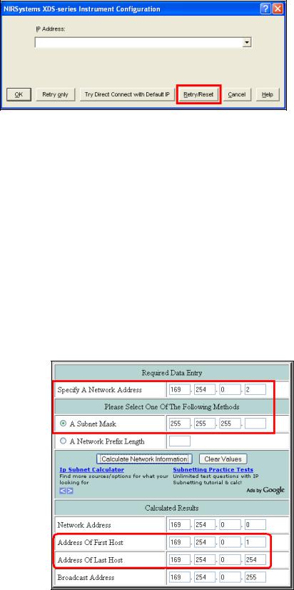
Windows 2000 users should click on “Retry/Reset”. This command resets the communication port, and also resets Windows 2000 to the proper state to connect using a dynamic IP address in the XDS instrument.
3.6.2Direct Connection Troubleshooting Overview
If no XDS instrument shows as “available”, the computer may need to be configured for the IP address range of the XDS instrument. It may be necessary to contact your IT department for assistance with these issues.
First, verify the following:
•The instrument is free-standing not connected to a network with DHCP server
•There is only one network card in the computer
•A crossover cable is used between the XDS instrument and the computer
If these conditions are met, please proceed.
Direct Connection Solution 1:
If using a crossover cable, verify that the computer is communicating in the same IP range as the XDS instrument.
The XDS instrument default IP address is 169.254.0.2, as shown. This address calculator gives the allowable computer IP address range as 169.254.0.1 through 169.254.2.254.
DO NOT use 169.254.0.2 in the computer!
Set the computer IP address to either:
•169.254.0.1, or
•169.254.0.3.
20 ▪▪▪▪▪▪▪
Direct Connection Solution 2:
Direct Connection
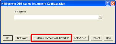
Solution 3:
Click on “Try Direct Connect with Default IP”. This searches for the default IP address stored in the instrument.
When the instrument is found, click “OK”
Power down the XDS Instrument, then power it back up. Wait 120 seconds, for the instrument to determine the correct method of Ethernet communication. Please do not click anything for this amount of time, or communication may be interrupted.
This should resolve the connection issue. Proceed to “Acquire” and “Connect” in Vision.
▪▪▪▪▪▪▪ 21

4 Assembly of the Instrument
The XDS Analyzer will be assembled and installed by a trained representative of Metrohm. This person will perform a full suite of diagnostics to verify correct operation, and will explain basic operating points. Assembly information is given as a guide for the user, should re-assembly ever be required due to an instrument move or for other reasons.
Verify that the following items have been received in good condition:
•Metrohm XDS Monochromator
•MultiVial module
•Vision Spectral Analysis Software (Vision Manual is on CD)
•Spare Lamp
•Accessory Kit, containing cords, cables, standard tray, and other required items
•Safety Manual for CE certification
•Instrument Test Results Packet
(Packaging of items may vary from that shown.)
The serial number of the instrument and module are located on serial plates on the left side, when facing the instrument. These serial numbers should match the serial numbers marked on the shipping papers.
When using Vision software, the software will automatically read the monochromator serial number. The module serial number must be entered manually, and is located on the module serial number plate on the left side of the module, facing the instrument.
22 ▪▪▪▪▪▪▪
DO NOT OPERATE OR TROUBLESHOOT WITH THE LID OPEN. SUNLIGHT MAY CONFUSE THE OPTICAL INTERRUPTERS USED TO POSITION THE SAMPLE CARRIAGE. THIS MAY CAUSE AN “X-Y POSITIONING ERROR” TO BE REPORTED.
Follow the assembly sequence that begins on the next page:
1Load Vision Spectral Analysis Software onto the computer designated to operate the XDS instrument.
2Place the monochromator on the lab bench in the position shown.
3Open the right-hand panel of the instrument. Pull it gently by a fin, until the catch releases. This panel opens to about a 45-degree angle for access to connectors, and for filter inspection. Avoid scratches or damage.
▪▪▪▪▪▪▪ 23

4Gently thread the AC power cable and network cable through the lower right corner of the instrument access area as shown.
The cables should snap into the black holder. The innermost position is large, to fit the power cord. If the power cord is in the wrong location, the door may not close fully.
The network cable may go into either of the other two locations.
5Insert the AC power cable into the AC power block as shown.
6Attach the RJ-45 cable to the network connector on the instrument. If using Direct Connection, use the gray cable from the instrument accessory kit.
If using network connection, do not use the gray cable, as it is a “UTP crossover” cable and will not work with a network. Use a network cable as described in section 3.0.
7Close the outer cover of the instrument. Push gently to the final closed position. It should latch securely.
24 ▪▪▪▪▪▪▪
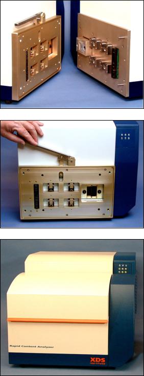
8Position the sampling module directly in front of the monochromator.
This photo shows the mating connection plates, prior to final alignment and assembly. The locating pins help find the final position.
The latches are used to lock the module in position.
9Lift the release handle on the monochromator and engage the module “catches” to the locking togs on the monochromator. (Module not shown to allow a good view of handle.)
Push monochromator and module together firmly (with handle up) then lower the release handle.
10When the catches are fully engaged to the locking togs, push the release handle down all the way.
This automatically engages the electrical connector and fiber optic interface, and maintains proper alignment of the module to the instrument.
The final assembly is as shown.
11Plug the AC power cord into a grounded AC outlet. A surge protector or Uninterruptible Power Supply (UPS) is recommended for best operation.
▪▪▪▪▪▪▪ 25
12If using a network, use a non-crossover type cable as listed in section 3.0. Plug the RJ-45 network connector into a functional network port.
If this requires approval from a network administrator, it should be properly approved for hookup.
For “Direct Connection” the gray cable from the instrument plugs directly to the computer network jack. (Use the cable supplied with the instrument.)
13When all the above assembly is finished, turn on the power switch on the monochromator. It is located on the lower surface, on the right-hand side as shown.
The monochromator performs some initialization tests, which take a moment. Some noises will be heard as items find their initial positions. This is normal.
14Prepare to establish communication from Vision to the XDS instrument. This is detailed in Section 6.0, Vision Software.
This completes assembly of the MultiVial Analyzer.
26 ▪▪▪▪▪▪▪
5 XDS MultiVial Module
The XDS MultiVial Analyzer is primarily designed for vial sampling, which is the focus of this manual. Optional sampling devices are available, and are also described following the vial information. For optional sampling accessories, please contact your Metrohm NIRSystems distributor.
5.1 Introduction to Vial Analysis
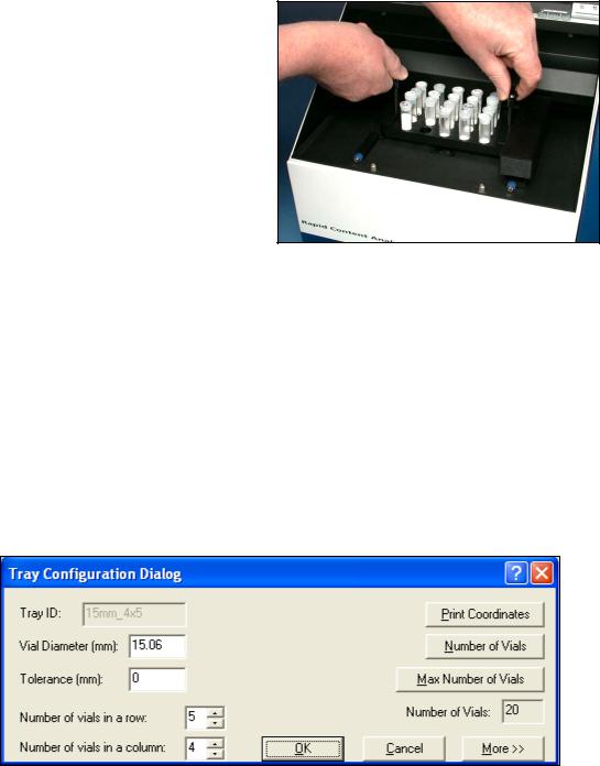
The MultiVial Analyzer is designed to provide sampling for trays of vials, like that shown at right. This provides for a greater degree of automation, and permits the operator to perform sample loading and other duties while one rack is being scanned by the instrument.
This extends the usefulness of the instrument into a routine analytical tool, since no operator input is required, once the sample information is entered and the rack is in place. Spectral information for each vial is acquired and stored, and the calibration or library identification is automatically applied.
Partial racks may be run, and the order of scanning determined by the user. Vision provides easy graphical tools to make setup easy and accurate. No special software skill is required to set up the instrument for routine analysis, once the calibration is in place.
Because the MultiVial may be used with different size vials, Vision accommodates setup by offering a screen to help define the tray dimensions, including vial spacing. The number of columns and rows of vials is entered, along with the manufacturer’s nominal diameter and tolerance. Vision takes this information and provides centerline data for each bored hole in the tray, which can be used for machining.
There are four default vial sizes set up in Vision, for commonly-used vials. The 15mm vial diameter is shown as an example:
The setup screen for sampling is straightforward and easy to use. An example is shown:
▪▪▪▪▪▪▪ 27

Step by step instructions are given later in this manual. Please see Section 6.2 for full information.
It is important that the “spot size” adjustment be set up properly for a given vial size. This is also covered in the section on Vision. Normally spot size should be no larger than 80% of vial size. However, this is not pre-set, as users may wish to scan a smaller area.
5.2 Creation of a Custom Vial Size
Most users will work with one of the standard vial sizes offered. However, for setup of custom sizes, this information is provided. To create a custom vial diameter, follow these steps:
From the menu bar, select Configure, Tray.
28 ▪▪▪▪▪▪▪
Loading...