


743
Table of contents
 Loading...
743 Rancimat
Manual
8.743.8003EN


Metrohm AG
CH-9100 Herisau
Switzerland
Phone +41 71 353 85 85
Fax +41 71 353 89 01
info@metrohm.com
www.metrohm.com
743 Rancimat
Manual
8.743.8003EN 03.2009 jb/ars

Teachware
Metrohm AG
CH-9100 Herisau
teachware@metrohm.com
This documentation is protected by copyright. All rights reserved.
Although all the information given in this documentation has been
checked with great care, errors cannot be entirely excluded. Should you
notice any mistakes please send us your comments using the address
given above.
Documentation in additional languages can be found on
http://products.metrohm.com under Literature/Technical documenta-
tion.

■■■■■■■■■■■■■■■■■■■■■■
Table of contents
1 Introduction 1
1.1 Instrument description ......................................................... 1
1.2 Rancimat method ................................................................. 2
1.3 About the documentation ................................................... 3
1.3.1 Symbols and conventions ........................................................ 3
1.4 Safety instructions ................................................................ 4
1.4.1 General notes on safety ........................................................... 4
1.4.2 Electrical safety ........................................................................ 5
1.4.3 Flammable solvents and chemicals ........................................... 6
1.4.4 Recycling and disposal ............................................................. 6
2 Overview of the instrument 7
3 Installation 10
Table of contents
3.1 Setting up the instrument .................................................. 10
3.1.1 Packaging .............................................................................. 10
3.1.2 Checks .................................................................................. 10
3.1.3 Location ................................................................................ 10
3.2 Mounting accessories ......................................................... 10
3.2.1 Mounting accessories for the internal air supply ..................... 10
3.2.2 Mounting accessories for the external air supply .................... 13
3.2.3 Equipping the reaction and measuring vessels ........................ 13
3.2.4 Inserting vessels / Establishing tubing connections ................. 16
3.2.5 Mounting the exhaust collection tube (optional accessories) .. 17
3.3 Mains connection ............................................................... 18
3.3.1 Checking the mains voltage ................................................... 18
3.3.2 Replacing fuses ...................................................................... 18
3.3.3 Mains cable and mains connection ........................................ 19
3.3.4 Switching the instrument on/off ............................................ 19
3.4 Connecting a PC ................................................................. 19
3.4.1 Connecting the 743 Rancimat and the PC .............................. 19
3.4.2 Installing the software ........................................................... 20
3.4.3 Carrying out basic settings ..................................................... 22
4 Operation 24
743 Rancimat
4.1 Fundamentals of operation ............................................... 24
4.1.1 Starting and exiting the program ........................................... 24
4.1.2 Terms .................................................................................... 25
4.1.3 Control window .................................................................... 25
4.1.4 Results window ..................................................................... 27
4.1.5 File types ............................................................................... 30
4.1.6 Context-sensitive menus ........................................................ 31
■■■■■■■■
III

Table of contents
■■■■■■■■■■■■■■■■■■■■■■
4.1.7 Mouse functions .................................................................... 31
4.1.8 Help ...................................................................................... 32
4.2 Instrument and Program Settings ..................................... 33
4.2.1 Establishing the instrument communication ........................... 33
4.2.2 Managing access rights ......................................................... 34
4.2.3 Timer ..................................................................................... 37
4.2.4 Gas flow control .................................................................... 39
4.2.5 Recording the temperature .................................................... 40
4.2.6 Optimizing program and database ......................................... 41
4.3 Program information ......................................................... 42
4.3.1 Instrument information .......................................................... 42
4.3.2 Status overview ..................................................................... 44
4.3.3 Displaying, filtering and deleting event overview .................... 45
4.4 Calibration functions .......................................................... 48
4.4.1 Determining cell constants ..................................................... 48
4.4.2 Determining Delta T .............................................................. 50
4.5 Methods .............................................................................. 55
4.5.1 Managing methods ............................................................... 55
4.5.2 Parameter description ............................................................ 60
4.6 Determinations ................................................................... 75
4.6.1 Preparing samples ................................................................. 76
4.6.2 Preparing the instrument and the accessories ......................... 79
4.6.3 Preparing the determination .................................................. 81
4.6.4 Starting the determination ..................................................... 83
4.6.5 Cleaning the instrument and accessories ................................ 83
4.6.6 Adjusting the method parameters during the determination .. 84
4.6.7 Stopping the determination manually .................................... 85
4.6.8 Status of the live curve ........................................................... 86
4.7 Results ................................................................................. 87
4.7.1 Determination overview ......................................................... 87
4.7.2 Determination and method data .......................................... 103
4.7.3 Graph and reevaluation ....................................................... 112
4.7.4 Extrapolation ....................................................................... 117
4.7.5 Recalculating a determination .............................................. 121
4.7.6 Printing and exporting data ................................................. 128
4.7.7 Program settings ................................................................. 135
4.7.8 Arranging windows ............................................................. 141
4.8 GLP functions .................................................................... 142
4.8.1 General information on GLP and validation .......................... 142
4.8.2 GLP monitoring ................................................................... 142
4.8.3 GLP status ........................................................................... 144
4.8.4 Carrying out GLP tests ......................................................... 145
4.8.5 GLP results .......................................................................... 156
■■■■■■■■
IV
743 Rancimat

■■■■■■■■■■■■■■■■■■■■■■
5 Handling and maintenance 160
6 Troubleshooting 164
7 Technical specifications 170
Table of contents
5.1 General information ......................................................... 160
5.1.1 Care .................................................................................... 160
5.1.2 Maintenance by Metrohm Service ........................................ 160
5.2 Replacing the dust filter .................................................. 161
5.3 Regenerating or replacing the molecular sieve ............. 161
5.4 Self test when switching on ............................................ 162
5.5 Quality Management and validation with Metrohm .... 163
6.1 Problems ........................................................................... 164
7.1 General data ..................................................................... 170
7.2 Temperature regulation and measurement ................... 170
7.3 Conductivity measurement .............................................. 171
7.4 Gas flow regulation .......................................................... 171
7.5 GLP test set ....................................................................... 172
7.6 RS-232 interface ............................................................... 172
7.7 Mains connection ............................................................. 172
7.8 Safety specification .......................................................... 173
7.9 Electromagnetic compatibility (EMC) ............................. 173
7.10 Ambient temperature ...................................................... 173
7.11 Housing ............................................................................. 174
8 Conformity and warranty 175
8.1 Declaration of Conformity ............................................... 175
8.2 Quality Management Principles ...................................... 176
8.3 Warranty (guarantee) ....................................................... 177
9 Accessories 178
9.1 Scope of delivery .............................................................. 178
9.2 Optional accessories ........................................................ 185
743 Rancimat
Index 188
■■■■■■■■
V

Table of figures
Table of figures
Figure 1 Measuring arrangement (schematic representation) ........................... 3
Figure 2 Front 743 Rancimat ........................................................................... 7
Figure 3 Rear 743 Rancimat ............................................................................ 8
Figure 4 Mounting accessories for the air supply (rear of the instrument) ...... 11
Figure 5 Equipping the reaction and measuring vessels ................................. 14
Figure 6 Equipping the reaction vessel for determining Delta T ...................... 51
Figure 7 Accessories for GLP test Temperature ............................................ 145
■■■■■■■■■■■■■■■■■■■■■■
■■■■■■■■
VI
743 Rancimat

■■■■■■■■■■■■■■■■■■■■■■
1 Introduction
1.1 Instrument description
The 743 Rancimat is a PC-controlled measuring device for determining the
oxidation stability of samples containing oil and fat.
It is equipped with two heating blocks each with 4 measuring positions
(channels). Every block can be heated individually, i.e. 4 samples can each
be measured at 2 different temperatures or 8 samples at the same temperature. The measurements at the individual measuring positions can be
started individually for this.
Operation of the 743 Rancimat is realized completely via a PC connected
to the RS-232 interface using the control and evaluation program 743
Rancimat. Up to 4 instruments can be connected to each PC, hence
allowing a maximum of 32 samples to be analyzed. The evaluation algorithm of the PC program determines the break point of the Rancimat
curve fully automatically and hence the induction time. Besides the induc-
tion time, the so-called stability time, i.e. the time duration until attaining a defined conductivity change, can also be determined. In the case of
conductivity changes (stages) which do not have anything to do with the
autoxidation, the evaluation can be interrupted for definite time intervals.
The results determined can be processed further by computer. In particular, the induction times can be converted to the default temperatures of
the corresponding standards.
1 Introduction
Each Rancimat curve can also be evaluated manually. A PC-supported
tangential method is available for this, in which you can position the tangents anywhere on your curves. This makes evaluations possible in
extreme cases as well.
The results of the determinations are saved in a database together with
all methods and determination data. Determinations can be searched for,
sorted, filtered, exported and printed in the program part for the results
display. Besides the graphic display of single and multiple curves, recalculation with altered parameters and extrapolation of the results to a definite temperature is also possible.
GLP (Good Laboratory Practice) and instrument validation are becoming
increasingly important. The 743 Rancimat enables GLP tests for temperature, conductivity and gas flow measurement. You determine whether
and which tests have to be carried out. You can also specify the time
interval between the tests as well as the requirements regarding accuracy.
If the GLP function has been selected, each result report will receive a
comment stating whether the GLP tests have been fulfilled. Metrohm
743 Rancimat
■■■■■■■■
1

1.2 Rancimat method
offers a GLP test set to carry out these tests (see Optional accessories,
page 185).
1.2 Rancimat method
The decay of vegetable and animal fats, which can be perceived in the initial stage through a deterioration of odor and taste (rancidity), is to a
great extent the result of chemical alterations caused by the effect of
atmospheric oxygen. These oxidation processes progressing slowly at
ambient temperatures are referred to as autoxidation. They start with
radical reactions on unsaturated fatty acids and undergo a process involving multiple stages resulting in diverse decomposition products, in particular peroxides as primary oxidation products and alcohols, aldehydes and
carboxylic acids as secondary oxidation products.
With the Rancimat method, the sample is exposed to an air flow at a
constant temperature between 50…220 °C (see Figure 1, page 3).
Highly volatile, secondary oxidation products (for the most part formic
acid) are transferred into the measuring vessel with the air flow, where
they are absorbed in the measuring solution (distilled water). Here the
conductivity is continuously registered. The organic acids can thus be
detected by increasing the conductivity. The time until occurrence of these
secondary reaction products is referred to as the induction time or induction period, which is a good indicator for the oxidation stability.
■■■■■■■■■■■■■■■■■■■■■■
The Rancimat method has been developed as an automated variant to the
extremely complex AOM (active oxygen method) for determining the
induction time of fats and oils. This method has become established
over the course of time and has been incorporated in various national and
international standards, e.g. AOCS Cd 12b-92 and ISO 6886.
■■■■■■■■
2
743 Rancimat
■■■■■■■■■■■■■■■■■■■■■■
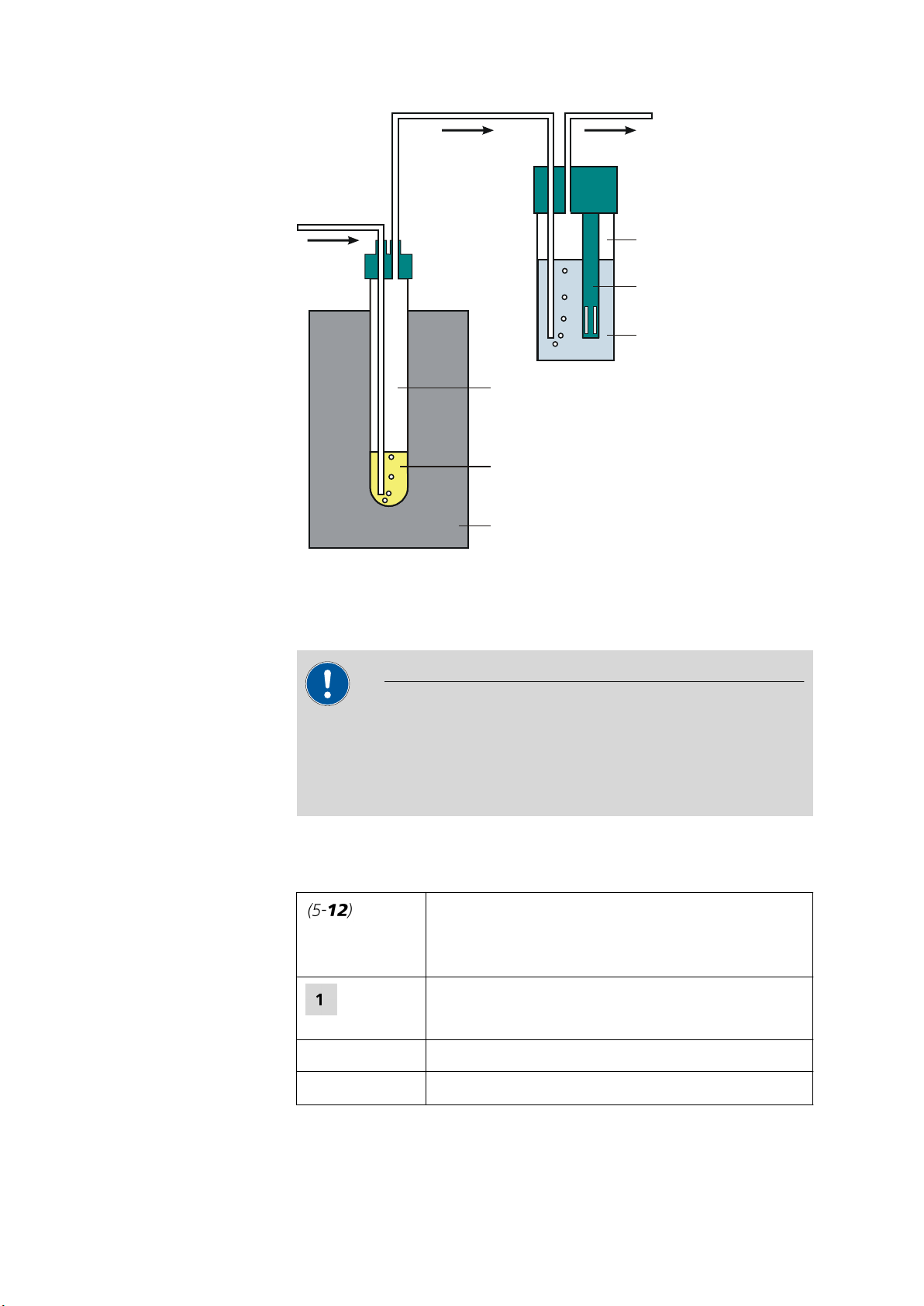
Reaction vessel
Sample
Heating block
Measuring
vessel
Conductivity
measuring cell
Measuring
solution
1 Introduction
Figure 1 Measuring arrangement (schematic representation)
1.3 About the documentation
Caution
Please read through this documentation carefully before putting the
instrument into operation. The documentation contains information
and warnings which have to be followed by the user in order to ensure
safe operation of the instrument.
1.3.1 Symbols and conventions
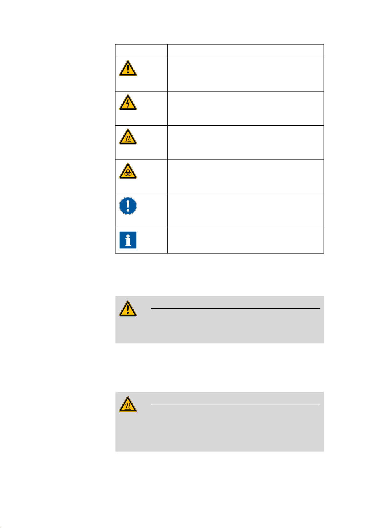
The following symbols and styles are used in this documentation:
Cross-reference to figure legend
The first number refers to the figure number, the
second to the instrument part in the figure.
Method Dialog text, parameter in the software
Instruction step
Carry out these steps in the sequence shown.
743 Rancimat
File ▶ New
Menu or menu item
■■■■■■■■
3
1.4 Safety instructions
■■■■■■■■■■■■■■■■■■■■■■
[Next] Button or key
Warning
This symbol draws attention to a possible life hazard
or risk of injury.
Warning
This symbol draws attention to a possible hazard due
to electrical current.
Warning
This symbol draws attention to a possible hazard due
to heat or hot instrument parts.
Warning
This symbol draws attention to a possible biological
hazard.
Caution
1.4 Safety instructions
1.4.1 General notes on safety
Warning
This instrument may only be operated in accordance with the specifications in this documentation.
This instrument has left the factory in a flawless state in terms of technical
safety. To maintain this state and ensure non-hazardous operation of the
instrument, the following instructions must be observed carefully.
Hot reaction vessels
This symbol draws attention to a possible damage of
instruments or instrument parts.
Note
This symbol marks additional information and tips.
■■■■■■■■
4
Warning
The reaction vessels can become very hot.
Avoid any contact with the hot reaction vessels. Place these in the vessel holders provided for cooling down.
743 Rancimat
■■■■■■■■■■■■■■■■■■■■■■
1 Introduction
Flammable substances
Warning
The oven of the 743 Rancimat can be heated to 220 °C.
Flammable substances may ignite at these temperatures.
Adjust the maximum heating temperature of the oven to the sample
being examined.
Defective glass vessels
Warning
Caution with defective glass vessels.
An overflow of flammable samples into the heating block can be dangerous.
Check the glass vessels before each use.
1.4.2 Electrical safety
The electrical safety when working with the instrument is ensured as part
of the regulations IEC 1010-1 (protection class 1, degree of protection
IP20).
Only personnel qualified by Metrohm are authorized to carry out service
work on electronic components.
Never open the housing of the instrument. The instrument could be
damaged by this. There is also a risk of serious injury if live components
are touched.
There are no parts inside the housing which can be serviced or replaced
by the user.
Warning
Warning
743 Rancimat
■■■■■■■■
5
1.4 Safety instructions
■■■■■■■■■■■■■■■■■■■■■■
Mains voltage
Warning
An incorrect mains voltage can damage the instrument.
Only operate this instrument with a mains voltage specified for it (see
rear panel of the instrument).
Protection against electrostatic charges
Warning
Electronic components are sensitive to electrostatic charges and can be
destroyed by discharges.
Always pull the mains cable out of the mains connection socket before
connecting or disconnecting electrical appliances on the rear panel of
the instrument.
1.4.3 Flammable solvents and chemicals
Warning
All relevant safety measures are to be observed when working with
flammable solvents and chemicals.
■ Set up the instrument in a well-ventilated location (e.g. laboratory
flue).
■ Keep all sources of flame far from the workplace.
■ Clean up spilled fluids and solids immediately.
■ Follow the safety instructions of the chemical manufacturer.
1.4.4 Recycling and disposal
This product is covered by European Directive 2002/96/EC, WEEE – Waste
from Electrical and Electronic Equipment.
The correct disposal of your old equipment will help to prevent negative
effects on the environment and public health.
More details about the disposal of your old equipment can be obtained
from your local authorities, from waste disposal companies or from your
local dealer.
■■■■■■■■
6
743 Rancimat
■■■■■■■■■■■■■■■■■■■■■■
743
Rancimat
11
10
9
8
7
6
5
4
3
2
1
2 Overview of the instrument
2 Overview of the instrument
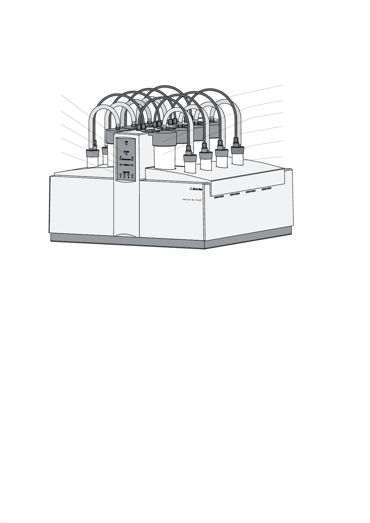
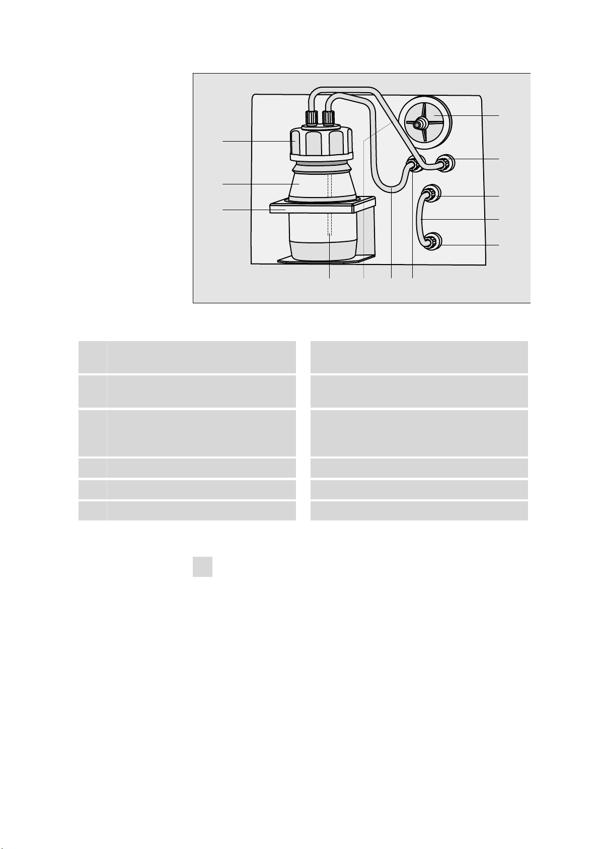
Figure 2 Front 743 Rancimat
743 Rancimat
■■■■■■■■
7
■■■■■■■■■■■■■■■■■■■■■■
Molecular sieve flask
Filter
Air out
2
Air/N in
Pt 100
RS 232
WARNING - Fire Hazard -
with the same type and rating of fuse
For continued protection replace only
100-115V: 4A(TH)
Fuse
Made by Metrohm Herisau Switzerland
From
flask
To
flask
220-240V: 2A(TH)
Type:
Nr.:
U:
f:
S:
14
3
4
5
6
8 9 10
13 15
16
18 19 20
1
2
Pilot lamp
1
Lights up when the instrument is switched
on.
Temperature display
3
Flashes when the heating is switched on.
Lights up when the temperature has been
reached.
Instrument number display
5
Indicates the number of the instrument.
Lights up if the instrument is registered.
Flashes (all LEDs) if the connection to the PC
is interrupted.
Measuring vessel cover (6.0913.130)
7
Contains an integrated conductivity measuring cell.
Silicone tubing (6.1816.010)
9
For connecting the reaction vessel to the
measuring vessel.
Reaction vessel (6.1429.040)
11
Gas flow display
2
Flashes when the gas flow is switched on.
Lights up when the gas flow has been
reached.
Error display (red)
4
Lights up or flashes when a fault has occurred in the instrument (see Troubleshooting
Chapter).
FEP tubing 250 mm (6.1805.080)
6
For supplying air into the reaction vessel.
Measuring vessel (6.1428.100)
8
Reaction vessel cover (6.2753.107)
10
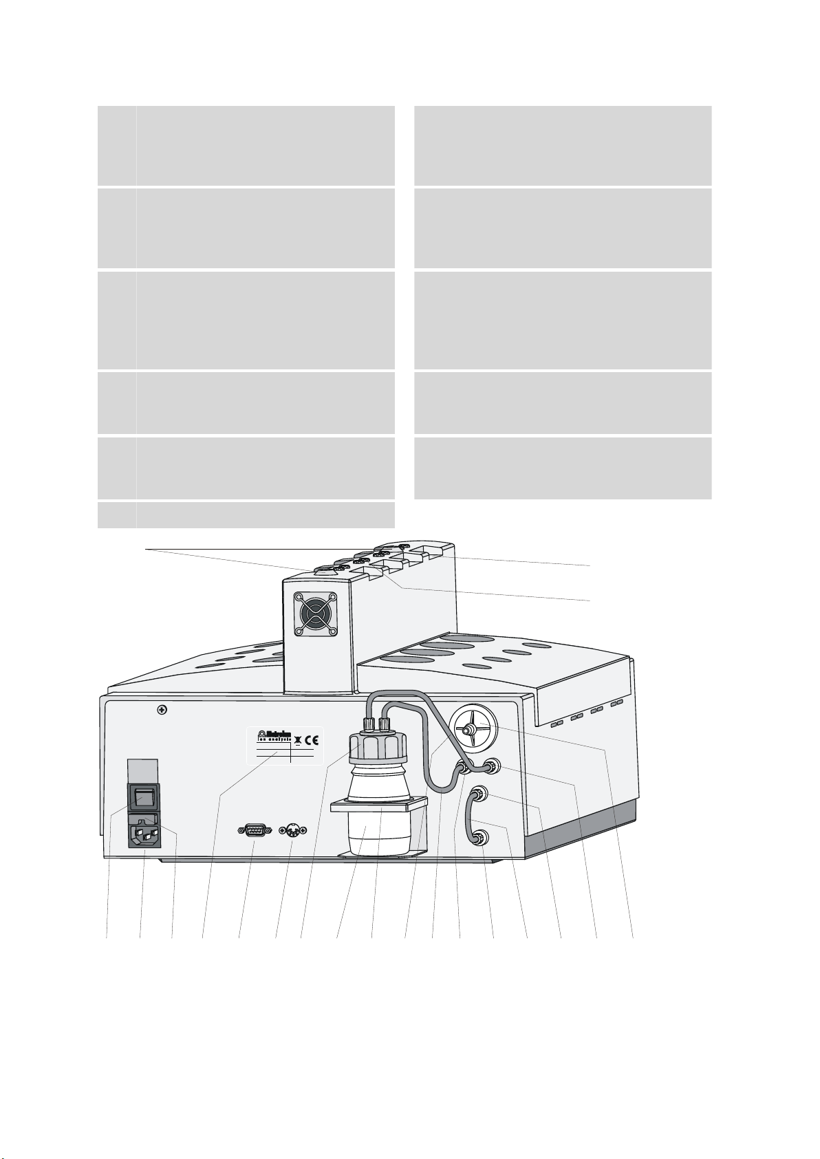
Figure 3 Rear 743 Rancimat
■■■■■■■■
8
743 Rancimat

■■■■■■■■■■■■■■■■■■■■■■
2 Overview of the instrument
Collection tube holder
1
For fastening the optional exhaust collection
tube (6.2757.000).
Air supply connection
3
For connecting the FEP tubing 250 mm
(2-6).
Mains connection socket
5
For important information on the mains connection, see Chapter 3.3.
Type plate
7
Contains specifications concerning mains
voltage and serial number.
Pt100 connector
9
For connecting an external temperature sensor.
Drying flask (6.1608.050)
11
FEP tubing 250 mm (6.1805.080)
13
For supplying the air from the internal pump
to the drying flask.
Electrode connector
2
For connecting the conductivity measuring
cell integrated in the measuring vessel cover
(2-7).
Mains switch
4
For turning the instrument on and off.
I = ON / 0 = OFF.
Fuse holder
6
Replacing fuses, see Chapter 3.3.2.
RS-232 connector
8
For connecting the PC.
Drying flask cover (6.1602.145)
10
Cover for the drying flask.
Flask holder
12
For fastening the drying flask.
FEP tubing 250 mm (6.1805.080)
14
For supplying the air from the drying flask to
the reaction vessel (2-11).
"From Flask" connection
15
FEP tubing 130 mm (6.1805.010)
17
For connecting the Air out connection to
the Air/N2 in connection during normal
operation with the internal air pump.
"To Flask" connection
19
"Air/N2 in" connection
16
"Air out" connection
18
Dust filter (6.2724.010)
20
743 Rancimat
■■■■■■■■
9
3.1 Setting up the instrument
3 Installation
3.1 Setting up the instrument
3.1.1 Packaging
The instrument is supplied in highly protective special packaging together
with the separately packed accessories. Keep this packaging, as only this
ensures safe transportation of the instrument.
3.1.2 Checks
Immediately after receipt, check whether the shipment has arrived complete and without damage by comparing it with the delivery note.
3.1.3 Location
The instrument has been developed for operation indoors and may not be
used in explosive environments.
■■■■■■■■■■■■■■■■■■■■■■
Place the instrument in a location of the laboratory suitable for operation
and free of vibrations, if possible protected from corrosive atmospheres
and contamination by chemicals.
The instrument should be protected against excessive temperature fluctuations and direct sunlight.
Note
In order to improve accessibility for the measuring positions, the instrument can be placed on the optionally available 6.2059.000 turning ring.
3.2 Mounting accessories
3.2.1 Mounting accessories for the internal air supply
The gas in the Rancimat is normally supplied using the internal air
pump, which sucks in laboratory air. For air supply and air purification,
the following accessories must be mounted on the rear of the Rancimat:
■■■■■■■■
10
743 Rancimat
■■■■■■■■■■■■■■■■■■■■■■
Molecular sieve flask
Filter
Air out
2
Air/N in
From
flask
To
flask
8
9
10
12
11
1
2
3
654 7
3 Installation
Figure 4 Mounting accessories for the air supply (rear of the instru-
ment)
Drying flask cover (6.1602.145)
1
Cover for the drying flask.
Flask holder
3
For fastening the drying flask.
FEP tubing 250 mm (6.1805.080)
5
For supplying the air from the internal pump
to the drying flask.
"From Flask" connection
7
"To Flask" connection
9
FEP tubing 130 mm (6.1805.010)
11
Mount the accessories for the air supply as follows:
1
Mount dust filter
■ Insert the dust filter (4-8) on the connection marked with Filter
■ If the laboratory air is heavily contaminated, a tubing for supply-
Drying flask (6.1608.050)
2
Filter tube (6.1821.040)
4
FEP tubing 250 mm (6.1805.080)
6
For supplying the air from the drying flask to
the reaction vessel (2-11).
Dust filter (6.2724.010)
8
"Air out" connection
10
"Air/N2 in" connection
12
on the rear of the Rancimat.
ing fresh air can be connected to the dust filter.
743 Rancimat
■■■■■■■■
11

3.2 Mounting accessories
■■■■■■■■■■■■■■■■■■■■■■
Note
The dust filter serves for filtering the air sucked through the air
pump and must be replaced at periodic intervals (see Chapter 5.2,
page 161).
2
Mount drying flask
Caution
Do not fill the hot molecular sieve directly into the drying flask
after regeneration, as otherwise the plastic filter on the filter tube
will melt.
Wait until the molecular sieve has cooled down before filling.
■ Fill the molecular sieve into the drying flask (4-2).
■ Screw the filter tube (4-4) on the lower side of the drying flask
cover (4-1) into the opening marked (above) with a dot.
■ Screw the drying flask cover with mounted filter tube onto the
drying flask and insert in the flask holder (4-3) on the rear of the
Rancimat.
■ Screw the one end of the FEP tubing 250 mm (4-6) onto that
opening on the drying flask cover at the bottom of which the filter tube is located.
■ Screw the other end of the FEP tubing onto the From flask con-
nection (4-7) on the rear of the Rancimat.
■ Screw the one end of the second FEP tubing 250 mm (4-5) onto
the second opening on the drying flask cover.
■ Screw the other end of the second FEP tubing onto the To flask
connection (4-9).
■■■■■■■■
12
Note
The molecular sieve serves for adsorbing interfering oxidizing gases
as well as water from the sucked in air. You can regenerate it in
the drying oven at +140…+180 °C for 24 to 48 h (see Chapter
5.3, page 161).
3
Mount the FEP tubing for the supply air
■ Screw the one end of the FEP tubing 130 mm (4-11) onto the Air
out connection (4-10).
743 Rancimat

■■■■■■■■■■■■■■■■■■■■■■
3 Installation
■ Screw the other end of the FEP tubing onto the Air/N
nection (4-12).
3.2.2 Mounting accessories for the external air supply
If the laboratory air is heavily contaminated, an external gas supply with
synthetic air can be provided. For this, the corresponding accessories must
be mounted on the rear of the Rancimat.
Mount the accessories for the external air supply as follows:
1
Mount the FEP tubing
■ Screw the one end of the FEP tubing 130 mm (4-11) onto the
Air/N2 in connection (4-12) on the rear of the Rancimat.
■ Screw the tubing adapter M6 / olive (6.1808.020) onto the other
end of the FEP tubing.
2
Connect the gas supply
■ Mount the gas supply from the bomb with synthetic air onto the
tubing adapter M6 / olive (6.1808.020).
in con-
2
Note
With an external gas supply, the gas flow cannot be regulated in the PC
program. The gas flow must be set manually using the reducing valve
and the gas flow display (see Chapter 4.2.4, page 39).
3.2.3 Equipping the reaction and measuring vessels
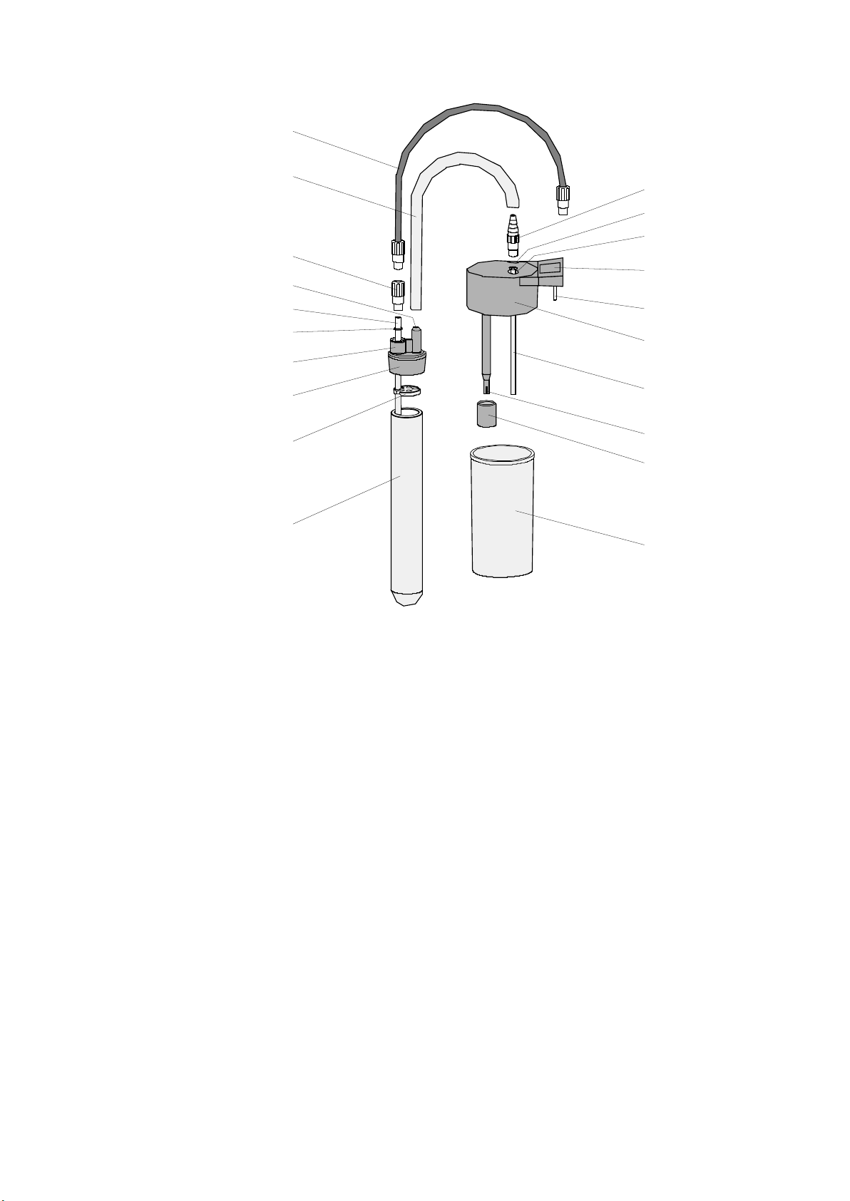
The following figure shows in detail, how the accessories parts for measuring the oxidation stability have to be mounted and connected to one
another.
743 Rancimat
■■■■■■■■
13
3.2 Mounting accessories
2
1
3
4
5
6
7
8
9
10
20
16
12
11
13
14
15
17
18
19
■■■■■■■■■■■■■■■■■■■■■■
Figure 5 Equipping the reaction and measuring vessels
■■■■■■■■
14
743 Rancimat

■■■■■■■■■■■■■■■■■■■■■■
3 Installation
FEP tubing 250 mm (6.1805.080)
1
For supplying air into the reaction vessel.
Thread adapter M8 / M6 (6.1808.090)
3
Air tube (6.2418.100)
5
Connection
7
For connecting the thread adapter M8 / M6.
Foam barrier (6.1451.010)
9
Tubing adapter M8 / olive (6.1808.050)
11
For connecting the silicone tubing to the
opening In (5-13).
Opening "In"
13
For supplying the air to the measuring vessel.
Connector plug
15
Silicone tubing (6.1816.010)
2
For connecting the reaction vessel to the
measuring vessel.
Tubing connector
4
For connecting the silicone tubing.
O-ring (6.1454.040)
6
Reaction vessel cover (6.2753.107)
8
Reaction vessel (6.1429.040)
10
Opening "Out"
12
For removing the air from the measuring
vessel.
Labeling field
14
For entering the cell constant.
Measuring vessel cover (6.0913.130)
16
Contains integrated conductivity measuring
cell.
PTFE tube (6.1819.080)
17
For supplying the air to the measuring solution.
Protection ring
19
Proceed as follows to mount the measuring and reaction vessel:
1
Mount the measuring vessel cover
■ Insert the PTFE tube (5-17) from above into the opening In (5-13)
■ Screw the tubing adapter M8 / olive (5-11) into the opening In of
■ Place the measuring vessel cover (5-16) on the measuring vessel
2
Mount the reaction vessel cover
■ Insert the air tube (5-5) from below into the connection (5-7) of
■ Place the O-ring (5-6) over the upper end of the air tube.
■ Screw the thread adapter M8 / M6 (5-3) gently into the connec-
Electrode
18
Measuring vessel (6.1428.100)
20
of the measuring vessel cover.
the measuring vessel cover.
(5-20).
the reaction vessel cover.
tion (5-7) and, at the same time, press the air tube against the
thread adapter M8 / M6.
743 Rancimat
■■■■■■■■
15

3.2 Mounting accessories
■ Now fix the air tube onto the reaction vessel cover by firmly pull-
■■■■■■■■■■■■■■■■■■■■■■
ing the thread adapter M8 / M6.
■ If determinations are carried out with highly foaming samples,
clamp the foam barrier (5-9) onto the air tube.
■ Place the reaction vessel cover on the reaction vessel.
Warning
The foam barrier can melt if it projects too deeply into the heating
block.
Ensure that the foam barrier (5-9) is at least 7 cm above the base of
the reaction vessel (5-10).
3.2.4 Inserting vessels / Establishing tubing connections
After you have assembled the reaction and measuring vessels, insert them
in the Rancimat and establish the tubing connections as follows:
1
Insert the measuring vessel
■ Fill the measuring vessel (5-20) with distilled water.
■ Place the measuring vessel cover on the measuring vessel.
■ Insert the measuring vessel into the openings provided on the
Rancimat. At the same time, carefully insert the connector plugs
(5-15) into the electrode connector (3-2).
■ Connect the white silicon tubing (5-2) to the tubing adapter
M8 / olive (5-11) of the measuring vessel cover.
2
Mount the tubings for the air supply
■ Screw the FEP tubings 250 mm onto the air supply connections
(3-3) of the Rancimat.
3
Insert the reaction vessel
■ Fill the reaction vessel (5-10) with the sample.
■ After reaching the required temperature, insert the reaction vessel
with the mounted reaction vessel cover in the openings provided
on the Rancimat.
4
Establish the tubing connections
■ Connect the white silicone tubing (5-2), which is fastened on the
measuring vessel cover, to the tubing connector (5-4) of the reaction vessel cover.
■■■■■■■■
16
743 Rancimat

■■■■■■■■■■■■■■■■■■■■■■
■ Screw the FEP tubing 250 mm (5-1), which is fastened on the
tubing adapter M8 / olive (5-11) of the Rancimat, onto the thread
adapter M8 / M6 (5-3) of the reaction vessel cover.
Note
Instead of the measuring vessel 6.1428.100 made from polycarbonate,
the optionally available measuring vessel 6.1428.020 made from clear
glass can be used. In contrast to the polycarbonate vessel, the measuring vessel 6.1428.020 can also be cleaned with acetone.
3.2.5 Mounting the exhaust collection tube (optional accessories)
The optionally available exhaust collection tube 6.2757.000 can be mounted on the 743 Rancimat for targeted removal of the exhaust air. In addition to the exhaust collection tube, 8 silicone tubings 6.1816.010
(220 mm) also have to be ordered.
Proceed as follows to mount the collection tube:
1
Mount the exhaust collection tube
■ Insert the exhaust collection tube with both nozzles into the col-
lection tube holders (3-1) on the Rancimat in such a way that the
connection to the exhaust air removal is located to the rear.
2
Connect the measuring vessels
3 Installation
■ Screw the tubing adapter M8 / olive (5-11) into the opening Out
(5-12) of the measuring vessel cover.
■ Connect the one end of the silicone tubing (5-2) to the tubing
adapter M8 / olive.
■ Insert the other end of the silicone tubing into the corresponding
opening on the collection tube.
■ Seal the unused openings on the collection tube with the
enclosed plugs E.400.0010.
3
Connect the exhaust collection tube
■ Connect a suitable tubing to the connection of the exhaust collec-
tion tube and connect this to an active suction device (e.g. water
jet pump).
743 Rancimat
■■■■■■■■
17
3.3 Mains connection
3.3 Mains connection
Warning
There is a risk of fire if the instrument is operated with an incorrect
mains fuse!
Follow the regulations below for the mains connection.
3.3.1 Checking the mains voltage
Before switching the 743 Rancimat on for the first time, check whether
the mains voltage indicated on the type plate (3-7) corresponds to the
mains voltage present. If this is not the case, please contact Metrohm
Service.
3.3.2 Replacing fuses
Two fuses 4 A (slow-acting) for 115 V or 2 A (slow-acting) for 230 V are
installed in the fuse holder (3-6) of the 743 Rancimat as standard.
■■■■■■■■■■■■■■■■■■■■■■
Warning
Ensure that the instrument is never put into operation with fuses of
another type, otherwise there is a risk of fire!
Proceed as follows to replace defective fuses:
1
Pull out the mains cable
■ Pull the mains cable out of the mains connection socket of the
Rancimat.
2
Remove the fuse holder
■ Use a screwdriver to loosen and completely pull out the fuse
holder (3-6) above the mains connection socket.
3
Replace fuses
■ Carefully take the defective fuses out of the fuse holder and
replace them with two new fuses suitable for the set mains voltage of the type TH (slow-acting, with high switching capacity):
– 115 V 4 A (TH) Metrohm No.: U.600.0022
– 230 V 2 A (TH) Metrohm No. U.600.0107
■■■■■■■■
18
743 Rancimat
■■■■■■■■■■■■■■■■■■■■■■
4
Insert the fuse holder
■ Push the fuse holder back into the instrument until it latches into
place.
3.3.3 Mains cable and mains connection
Mains cable
The mains cable optionally supplied for the instrument
■ 6.2122.020 with plug SEV 12 (Switzerland)
■ 6.2122.040 with plug CEE(7), VII (Germany, …)
■ 6.2122.070 with plug NEMA 5-15 (USA, …)
is three-core and provided with a plug with grounding pin. If another plug
has to be mounted, the yellow/green conductor (IEC standard) must be
connected to the protective ground (protection class I).
Warning
3 Installation
Any interruption to the grounding within or outside the instrument can
make it dangerous!
Mains connection
Plug the mains cable into the mains connection socket of the Rancimat.
3.3.4 Switching the instrument on/off
The Rancimat is switched on and off using the mains switch. When
switching the instrument on, the pilot lamp ON lights up on the front of
the instrument auf.
3.4 Connecting a PC
3.4.1 Connecting the 743 Rancimat and the PC
Caution
Always switch the Rancimat and PC off before you connect the two
devices with the RS-232 cable 6.2134.100.
743 Rancimat
The PC program 743 Rancimat allows control of max. 4 instruments.
The following options are available for connecting the instruments to
serial PC interfaces:
■ Connection to integrated COM interfaces of the PC
■ Connection to an additional integrated interface expansion card
■■■■■■■■
19

3.4 Connecting a PC
Connect the RS-232 interface of the Rancimat to the required serial COM
port on the PC using the RS-232 cable 6.2134.100 (9-pin/9-pin). For 25pin COM ports, the optional RS-232 cable 6.2125.110 (not in the scope of
delivery) or a commercially available adapter must be used.
3.4.2 Installing the software
3.4.2.1 System requirements
Operating system Windows 2000, Windows XP Professional, Win-
RAM 256 MB (Windows 2000 / Windows XP)
Processor Pentium III or higher
Memory approx. 20 MB for program files
RS-232 interface one free RS-232 interface (COM)
The windows user must have administrator rights in order to be able to
install 743 Rancimat.
■■■■■■■■■■■■■■■■■■■■■■
dows Vista
1 GB (Windows Vista)
3.4.2.2 Installing the program
Proceed as follows to install 743 Rancimat:
1
Start the installation program
■ Place the installation CD in the CD drive. The installation program
is started automatically.
If this option is deactivated on your computer, double click the file
Setup.exe.
Windows Vista: Select the option "Approve".
■ Click on 743.
2
Select the dialog language
■ Select the dialog language of the program.
■ Click on the [OK] button.
■ Click on the [Next >] button.
3
Accept the license agreement
■ Read through the license agreement and accept it with [Yes].
4
Define a target folder for the program
■ If required, choose another folder than the default target folder
for the program files. For that, click on the [Browse...] button.
■ Confirm the target folder with [Next >].
■■■■■■■■
20
743 Rancimat

■■■■■■■■■■■■■■■■■■■■■■
5
Define the components of the program
■ Click on the [Next >] button.
6
Define a target folder for the program icon
■ Choose or enter the program folder of the Start menu in which
The program will be installed.
7
Complete the installation
■ Click on the [Finish] button after the successfully completed
The installation program will be exited.
3.4.2.3 Windows Vista
3 Installation
the program icon is to be inserted and confirm with [Next >].
installation.
Caution
If you run the software 743 Rancimat on a computer with Windows
Vista, you need a special update in order to be able to display the help.
Due to licensing reasons you have to download this file from a Microsoft web page. On the installation CD the link "Download Win-
Help.url" to the corresponding Microsoft web page can be found in
the folder "Vista Update for HLP help". Download the necessary
installation file and save it.
Proceed as follows to install the update:
■ Exit 743 Rancimat if you have started the software after the instal-
1
lation.
■ Start the installation file by double-clicking and follow the instruc-
tions of the installation program.
743 Rancimat
■■■■■■■■
21
3.4 Connecting a PC
3.4.3 Carrying out basic settings
Setting the Administrator password
When starting the program for the first time, the Administrator password
must be set. Proceed as follows:
1
Switch on the instruments
■ Check whether the Rancimat is correctly connected to the PC (see
Chapter 3.4.1, page 19).
■ Switch on the Rancimat using the mains switch.
■ Switch on the PC.
2
Start program
■ In the Windows Start menu under Pro-
grams ▶ Metrohm ▶ Rancimat, click on the menu item Rancimat.
■■■■■■■■■■■■■■■■■■■■■■
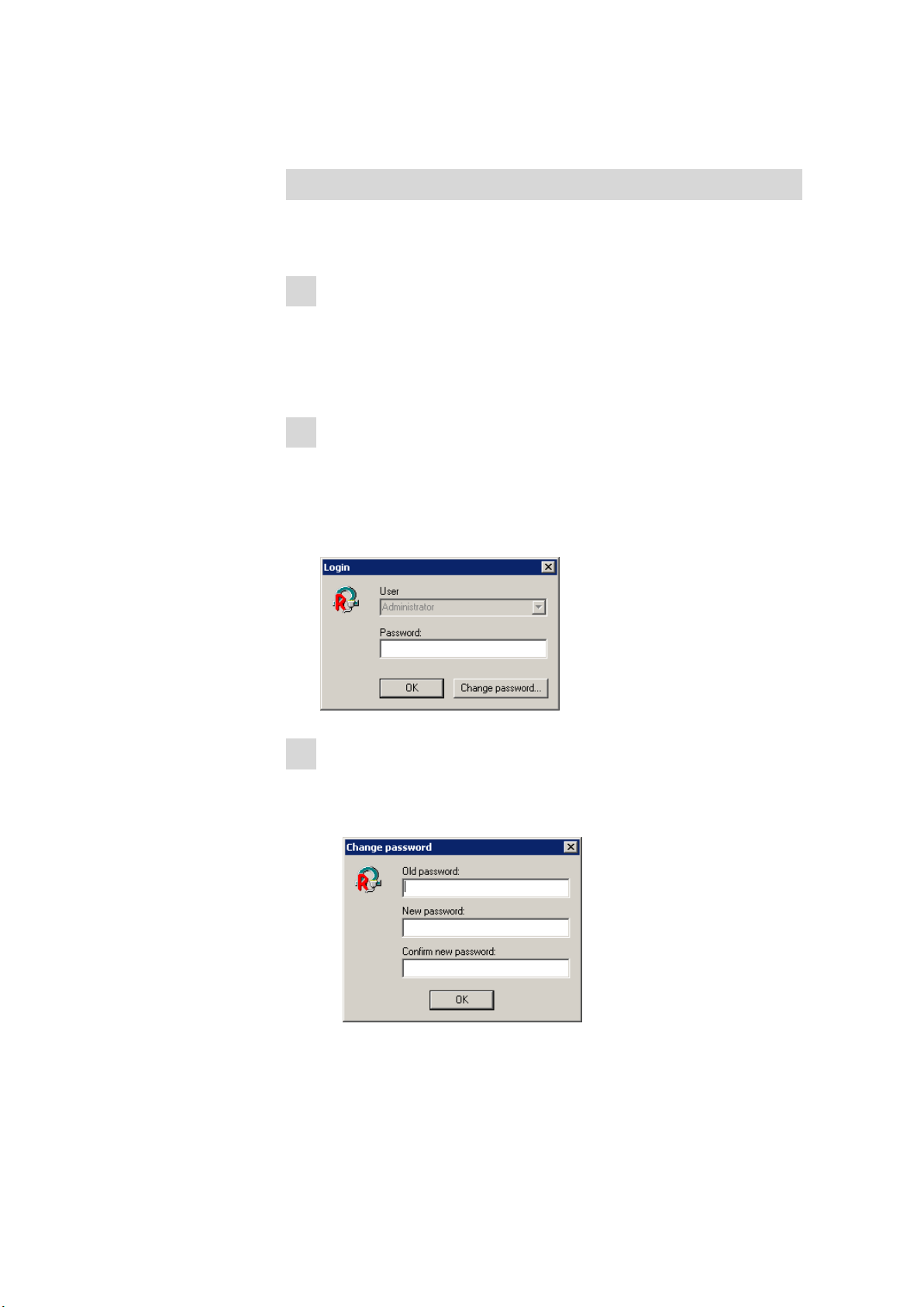
The login window for the Administrator opens:
3
Set Administrator password
■ Do not enter a password, instead click on [OK].
■ Confirm the displayed message with [OK].
The following dialog window appears:
■■■■■■■■
22
■ Leave the Old password field empty.
■ Enter a new password for the Administrator in the New pass-
word field.
743 Rancimat
Loading...