

Mercedes-Benz XENTRY Kit 2, XENTRY Kit MT 2, XENTRY Connect, XENTRY Tab 2 User Manual
User Guide
XENTRY Kit 2
XENTRY Kit MT 2
XENTRY Connect

2
Important: Read carefully before using! Retain for future reference
Version 1.3 last updated 09/2014
Copyright 2014 Daimler AG. All rights reserved. All texts, pictures, graphics, audio, video and animation les, as well as their arrangements, are subject to copyright protection
and other statutes for protecting intellectual property. They may neither be copied for commercial purposes nor for dissemination, nor may they be modied or used on other
websites. Some of the Daimler AG webpages also include material which is subject to the copyright protection of those parties who have made it available.

6 XENTRY Connect 21
6.1 Technical Performance Features 21
6.2 Interfaces on the XENTRY Connect 21
6.2.1 Socket for the XENTRY Connect power supply unit 21
6.2.2 USB Connections 21
6.2.3 Connecting XENTRY Connect to the vehicle (cable) 22
6.3 XENTRY Connect operating panel 22
6.3.1 Button Lock on the XENTRY Connect 22
6.3.2 LEDs and Search Tone 22
6.3.3 Display 23
6.3.4 Upper section of the XENTRY Connect display 23
6.3.5 Lower section of the XENTRY Connect display 24
6.3.6 Background Illumination Statuses 24
6.3.7 Buttons of the XENTRY Connect 24
6.4 Starting and Shutting Down the XENTRY Connect 25
6.5 Battery Compartment 25
7 XENTRY Tab 2 26
7.1 Technical Performance Features 26
7.2 Interfaces on the XENTRY Tab 2 26
7.3 XENTRY Tab 2 function buttons 27
7.4 Panasonic Dashboard 27
7.5 Virtual Keyboard 27
7.6 Own Software on the XENTRY Tab 2 27
7.7 XENTRY Tab 2 docking station 28
7.8 Printers and Printing 28
7.9 XENTRY Printer Bridge 28
7.10 Windows Settings 28
Table of Contents
1 Safety information and
product liability 5
2 New Features with XENTRY Kit 2 7
3 Scope of supply 8
3.1 XENTRY Kit 2 scope of supply 8
3.2 XENTRY Connect scope of supply 8
3.3 XENTRY Tab 2 scope of supply 9
4 System Requirements and Network Integration 10
4.1 Network Proles: Connecting the XENTRY Connect
to the XENTRY Tab 2 11
4.1.1 Workshop Mode 11
4.1.2 Service24h mode 11
4.1.3 Cabled online mode 12
4.1.4 Mixed Operation 12
4.2 Minimum technical requirements and restrictions on
use of a standard PC 12
5 InitialStartupandConguration 13
5.1 Brief overview of initial XENTRY system startup 13
5.2 Conguration of the overall system 14
5.2.1 Conguration (dialog-guided, CongAssist) 14
5.2.2 Expert mode initial startup 16
5.3 Checking the Back-end Connections 18
5.4 Order StartKey 19

8 Connection of Accessories 29
8.1 XENTRY Measurement Technology HMS 990 USB 29
8.2 SBC Flash Box 29
8.3 MoTelDis 30
8.4 Chip Card Reader 30
8.5 Injector scanners (2D hand-held scanners) 30
8.6 Diagnostic unit for HV batteries 30
9 XENTRY Control 31
9.1 Starting XENTRY Control 31
9.2 XENTRY Control selection screen 31
9.2.1 XENTRY Connect statuses 32
9.2.2 Menu and displays in the XENTRY Control
selection screen 32
9.3 Working with XENTRY Control and
XENTRY Connect 33
9.3.1 Deskband 34
9.3.2 Deskband pop-up 34
10 Operating tools 36
10.1 Support Tool 36
10.2 StartKey Center 37
10.3 UpdateAssist 38
10.4 AddOn Center 38
11 Update & Recovery 40
11.1 XENTRY Connect update 40
11.1.1 XENTRY Kit 2 Software Blu-ray Disc 40
11.1.2 XENTRY Connect online update (add-ons) 41
11.2 XENTRY Connect recovery 41
11.3 XENTRY Tab 2 update 41
11.3.1 XENTRY Kit 2 Software Blu-ray Disc (BD) 41
11.3.2 XENTRY Tab 2 online update (add-ons) 42
11.3.3 Windows Updates on the XENTRY Tab 2 42
11.3.4 Virus Scanner Update 42
11.4 XENTRY Tab 2 Recovery 42
11.5 Recovery of the XENTRY Tab 2 42
11.5.1 Windows 7 (32-bit) Installation 42
11.5.2 Installation of the XENTRY Kit 2 Software
Blu-ray Disc (BD) 46
12 XENTRY HMS 990 USB
Measurement Technology 49
12.1 Components 50
12.2 Connecting the hardware 51
12.3 Software 52
12.4 Starting and shutting down 52
12.5 Automatic software download when starting the
XENTRY HMS 990 USB Measurement Technology 52
12.6 Display and status area in the main menu 54
12.7 Menu items and submenus 54
13 Automatic Quick Test (AKT) 58
13.1 Prerequisites for AKT 58
13.2 Activation / deactivation of AKT 58
13.2.1 AKT activation 58
13.2.2 AKT generation 59
13.2.3 AKT deactivation 60
13.3 Notes on XENTRY Portal and AKT 60
13.4 AKT-supported model series 60
14 Service & Support 61
14.1 Diagnosis User Help Desk (UHD) 61
14.2 Accessory Article Order Numbers 61
14.3 Activation of the Wireless Network Connection/
WLAN Adapter 62
15 Certication 63
15.1 Device Certication 63
15.1.1 XENTRY Connect 63
15.1.2 XENTRY Tab 2 63
15.1.3 Blu-ray drive 63
15.2 WLAN Certication 64
15.2.1 XENTRY Connect and XENTRY Tab 2 64
16 List of Illustrations 69
17 Windows 7 Licensing Policies 71

5
User Guide XENTRY Kit 2, XENTRY Kit MT 2, XENTRY Connect Daimler AG, Item No. 6511 9538 02, Last updated: 09/2014
1 Safety information and
product liability
Carefully read this operating and safety information before using the device.
THESE SAFETY INSTRUCTIONS MUST BE STRICTLY OBSERVED!
General safety information
When working with the diagnostic systems, various safety instructions apply as in the case of other workshop operations.
Special safety information is not provided for each compo-
nent, as the provided information is to be applied analogously to components that are not mentioned.
1. Read all instructions in the literature supplied
before you use the unit.
2. Follow the installation instructions in this user guide.
3. Only use the system as specied in the manufacturer’s
instructions, otherwise security may be aected.
4. Only use system components which are part of the
scope of supply, and heed the descriptions in this
user guide.
5. Never use the system components in the vicinity
of open ames or chemical liquids.
6. Internal arcing may occur and sparks may be formed
when the systems are in use. Due to explosion
protection reasons, all switches, connectors and
other spark-forming units must therefore be located
a minimum distance of 46 cm away from the ground.
7. Maintain a minimum distance of 13 cm between
electrical devices which generate a strong magnetic eld
(e.g. motors, magnets, televisions, refrigerators and large
speakers) and the computer.
8. Use only approved power cables.
9. Do not use any defective cables, damaged
or destroyed system components.
10. Do not use the device with defective cables or after
damage (e.g. dropping) until it has been inspected /
serviced by the personnel authorized to do this.
11. If extension cables are needed, only use suitable cables
that are authorized for the power input, as unsuitable
connections can overheat and cause res.
12. Make sure that all cables are routed properly so that
there is no danger of tripping and no possible damage
can be caused by working procedure in the workshops.
13. Never allow cable connections to hang over sharp
corners or edges, and never allow them to come into
contact with hot or moving vehicle components.
14. Make sure that the unit is grounded. Connect the power
cable to a properly grounded socket.
15. Do not connect or release any cables during a storm,
as this may otherwise lead to an electric shock. Do not
undertake any installation, maintenance
or reconguration during this time.
16. Remove electrical connections from the power supply
when they are not in use.
17. Do not route adapter or connection cables close
to hot parts. There is danger of damage.
18. Do not route adapter or connection cables close
to high voltage parts. This might cause interference.
19. Damaged, broken or bent pins in the plugs can lead
to damage to the vehicle/unit and can negatively aect
the user’s health.
20. Have diagnostic systems installed, maintained,
recongured, serviced and repaired by authorized
persons only.
21. Do not carry out any repairs yourself. Contact the
User Help Desk with regard to repairs.
22. Never pull on the cables to pull out a plug;
pull on the plug itself.
23. Let all parts cool down before you transport them.
24. Do not use additional substances to cool the system.
25. Do not operate the device in the vicinity of open fuel
containers to avoid the risk of an explosion or re.
26. Do not use the system on a damp surface or in the rain,
otherwise this may lead to electrical damage.27. Do
not use tools to open the components
to perform repairs.
28. Only perform all work in the engine compartment when
the engine is not running and the ignition is switched o.
Danger of injury due to rotating or hot parts.
29. When performing necessary checks on running engines,
route the test lines at a sucient distance from the
engine area.
30. The operation of wireless communication networks
and the operation of systems within these networks
is subject to the rules and regulations valid in your
country. Please consult the appropriate authorities
for more information. Familiarize yourself with the
country-specic regulations for the operation of wireless
communication networks in your market.

6
XENTRY Connect Safety Information
1. Keep the unit in a cool and dry location.
2. The ideal operating temperature is a room temperature
of 20°C; however, the device can be operated
at ambient temperatures of 0°C to 50°C.
3. The housing surface heats up during operation.
4. The device may only be stored in areas where
it is protected against dust, humidity, and spraying
and dripping water, and at a storage temperature of
-20°C to +60°C.
5. Only approved USB devices may be connected.
6. Only use the cables provided.
7. Only use the power supply unit included on delivery
when supplying power via the round DC jack
(next to the USB jacks).
8. The vehicle interfaces are designed exclusively for 12 V
on-board electrical systems (38-pin K-lines) and have an
upper supply voltage limit of 16.0 V. In other cases, for
a rated supply voltage of 13.5 V, the supply voltage has
an upper limit of 32 V and a lower limit of 8 V.
9. Only trained personnel may remove the housing screws
to open the housing.
10. WARNING: For explosion protection reasons, the
XENTRY Connect must be operated at least 46 cm
above the ground in order to rule out the ignition
of pools of ammable gases!
11. Liability and warranty claims based on improper use
of the device will not be accepted. The same applies
to direct and indirect damage that can occur due to
improper or incorrect device use.
12. If one of the warranty terms is found to be invalid, the
laws of the Federal Republic of Germany apply.
13. If USB devices with an external power supply are used,
the protection class of the power supply must comply
with the following guidelines: fully insulated – protection
class II identied with (as per VDE 0100 Section 410,
412.2.1.1)
IMPORTANT SAFETY INSTRUCTIONS RELATING TO
1. Read all instructions.
2. Do not operate equipment with damaged cable
or if equipment has been damaged – until it has been
examined by a qualied serviceman.
3. To protect against risk of re, do not operate equipment
in the vicinity of open containers of fuel (gasoline).
4. To reduce the risk of electric shock, do not use
on wet surfaces or expose to rain.
5. Adequate ventilation should be provided when working
on open combustion engines.
6. Use only as described in the manual. Use only
manufacturer’s recommended attachments.
7. WARNING: Risk of explosion. This equipment has internal
arcing or sparking parts which should not be exposed
to ammable vapor. This equipment should be located
at least 460 mm (18 inches) above the oor.
8. Ethernet (RJ45) is not intended for direct connection
to telecommunication networks.
SAVE THESE INSTRUCTIONS
XENTRY Tab 2 Safety Information
The safety information for the XENTRY Tab 2 can be found
in paper form in your system’s case.
XENTRY HMS 990 USB Measurement Technology Safety
Information
Only use the inputs of the HMS 990 USB Measurement Technology to measure motor vehicle on-board electrical system
voltages and motor vehicle currents.
Theft Protection
A PC security lock (e.g. Kensington lock) can be installed to
secure the XENTRY Tab 2 and the XENTRY Connect. The installation opening is located on the upper side of the devices.
Product liability
Infringements of or failure to observe the instructions in
this user guide may lead to damage. Daimler AG rejects any
liability in this event.
7
User Guide XENTRY Kit 2, XENTRY Kit MT 2, XENTRY Connect Daimler AG, Item No. 6511 9538 02, Last updated: 09/2014
2 New Features with XENTRY Kit 2
The essential advancement of the XENTRY Kit 2 in
comparison with Star Diagnosis consists of the XENTRY
Connect multiplexer having been supplemented with a
PC section with an operating system (Windows 7). The
diagnostic applications, such as XENTRY Diagnostics, run
on the XENTRY Connect. Operation and display are carried
out using the XENTRY Tab 2 tablet PC or optionally with a
standard Windows 7 PC.
The interoperability of the components is based on the
concept of a remote connection, so that access to XENTRY
Connect takes place from the XENTRY Tab 2 / standard PC.
This is carried out with the new XENTRY Control software,
which establishes the necessary remote connection and
enables operation.
In summary, the XENTRY Kit 2 product concept oers
various advantages:
• Improvement of system stability through direct,
cable-based communication between the vehicle and
XENTRY Connect (close-proximity vehicle diagnosis)
• New working options:
- An employee can work in parallel on several vehicles
with one XENTRY Tab 2 and several XENTRY Connect
devices
- An employee can request help and be supported
by a colleague on his XENTRY Connect
• Increased exibility through the alternative option
of using a standard PC instead of the XENTRY Tab 2
The new diagnostic generation is available
in the three versions:
• XENTRY Kit 2 (XENTRY Connect & XENTRY Tab 2)
• XENTRY Kit MT 2 (XENTRY Kit 2 & HMS 990 USB
Measurement Technology)
• XENTRY Connect (only XENTRY Connect)
• XENTRY Tab 2 (just XENTRY Tab 2, only available
as purchased device)
Which steps will be required before
you can begin diagnosis?
These brief instructions provide a simplied overview.
Also read through the following chapters in this user guide
under all circumstances to enable you to work properly
with the XENTRY system.
Step 1: Switch on both devices.
Step 2: Conguration of both devices for your network,
i.e. you have to congure the XENTRY Connect
and XENTRY Tab 2.
Step 3: Call the XENTRY Control software using
the link on the XENTRY Tab 2.
Step 4: Connection to a free XENTRY Connect with
which you would like to work.
Step 5: Usual work procedure: once the connection
to the XENTRY Connect has been established,
you will see the Diagnosis Desktop. This runs on
the XENTRY Connect. Here, you can launch and
continue to work as usual with familiar diagnostic
programs such as e.g. XENTRY Diagnostics.
Figure 1: XENTRY system overview
Note: For additional product information, as well as tips
on operating and working with the XENTRY Kit 2, please see
the product videos in our Mercedes-Benz After Sales portal.
8
3 Scope of supply
The scopes of supply dier depending on which system version you have requested.
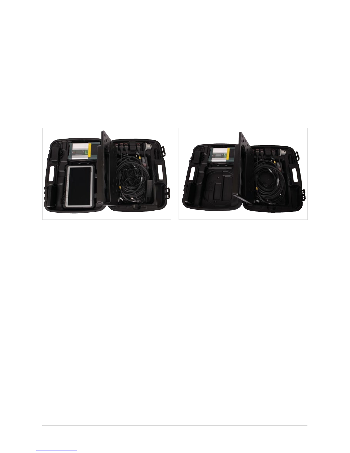
3.1 XENTRY Kit 2 scope of supply
Figure 2: XENTRY Kit 2 scope of supply
Components
XENTRY Tab 2 + country-specic power cable
XENTRY Connect + country-specic power cable
Set of small parts
Ethernet connecting cable 5 m
8-pin, 14-pin, 16-pin, 38-pin cables
User documentation
User guide
User manual for XENTRY systems
Help cards
Panasonic safety information
Accessories
Blu-ray disc drive + power supply unit
XENTRY Kit 2 Software Blu-ray Disc (BD)
3.2 XENTRY Connect scope of supply
Figure 3: XENTRY Connect scope of supply
Components
XENTRY Connect + country-specic power cable
Set of small parts
Ethernet connecting cable 5 m
8-pin, 14-pin, 16-pin, 38-pin cables
User documentation
User guide
User manual for XENTRY systems
Help cards
Accessories
Blu-ray disc drive + power supply unit
XENTRY Kit 2 Software Blu-ray Disc (BD)
9
User Guide XENTRY Kit 2, XENTRY Kit MT 2, XENTRY Connect Daimler AG, Item No. 6511 9538 02, Last updated: 09/2014
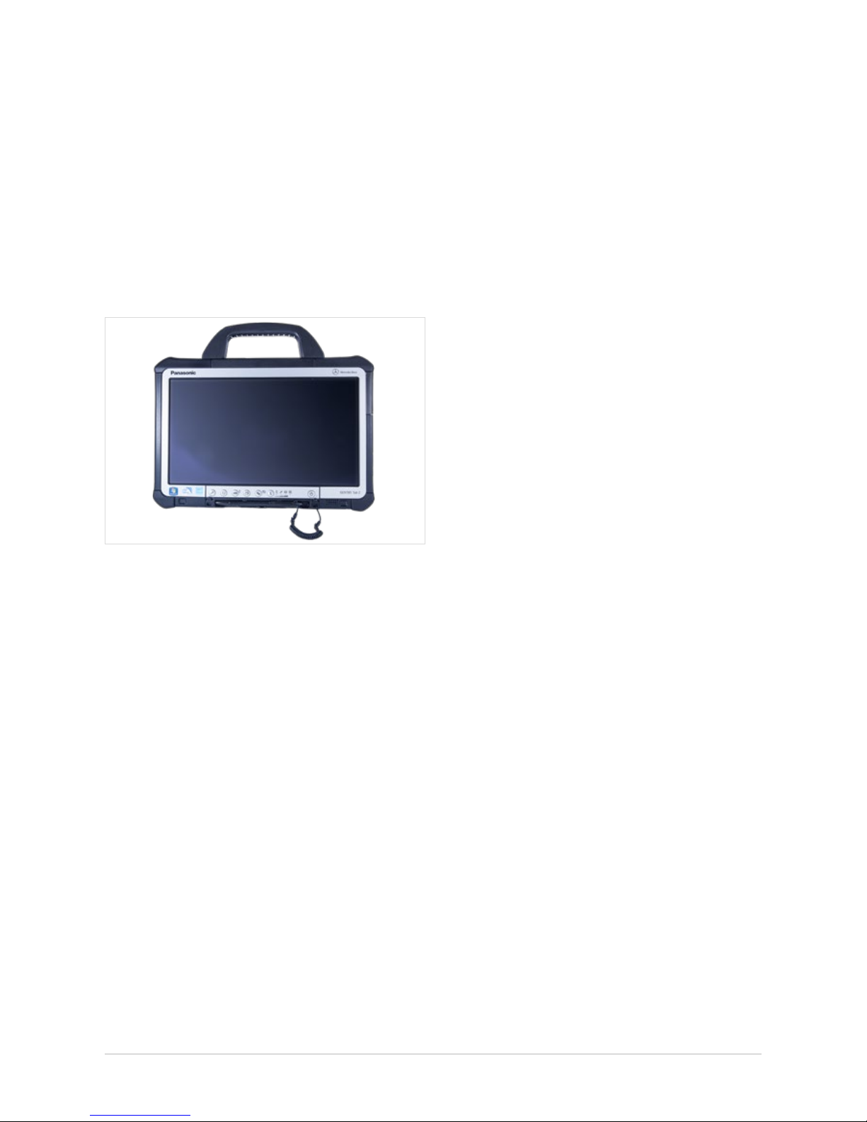
3.3 XENTRY Tab 2 scope of supply
Figure 4: XENTRY Tab 2
Components
XENTRY Tab 2 + country-specic power cable
User documentation
User guide
User manual for XENTRY systems
Help cards
Panasonic safety information
Accessories
XENTRY Kit 2 Software Blu-ray Disc (BD)

10
4 System Requirements and
Network Integration
• XENTRY Kit 2 supports the WLAN standard 802.11a/g/n.
The minimum requirement for the WLAN network is IEEE
802.11g wireless radio operation with a bandwidth of 2.4 GHz.
• We recommend encryption type WPA2 for conguring your
WLAN network. This encryption type oers the greatest
security. Encryption type WEP is no longer supported by
the new product concept.
• Make sure that the WLAN connection between XENTRY
Connect and Access Point is not screened e.g. by vehicles
or metal cabinets.
• If you operate your devices in Service24h mode, please
note that no online connection to back-end systems
(e.g. After Sales Portal, XENTRY Flash, add-ons, etc.)
is available in this mode.
• Make sure that the components' MAC addresses
(XENTRY Connect and XENTRY Tab 2/standard PC) are
enabled for your workshop’s WLAN and LAN on the
DHCP server.
• Please note that the number of systems which can access
the Internet at the same time is restricted in certain
workshops. With the XENTRY Kit 2, two components can
access the Internet. If necessary, clarify this with your
IT manager.
• Please note that you require two LAN sockets plus an
additional LAN cable (recommended length 20 m) per
workstation to operate the devices in workshop mode
via LAN, as only one LAN cable is supplied with the
XENTRY Kit 2. If you only have one LAN jack per workbay,
we recommend the use of a commercially available
LAN hub/splitter.
• When installing printers, make sure that these use
a current Windows 7 printer driver. Only printers
compatible with Windows 7 are supported by the system.
• For the XENTRY Kit 2 to function correctly, a DNS service
must be accessible in the workshop’s network. The
recommended conguration for XENTRY Kit 2 is automatic
procurement of the IP address conguration via a DHCP
server in the internal network. This recommendation
applies in equal measure to both large and small
companies.
• Please ensure that these devices retain a clear line-of-sight
connection to one another at all times, both in the
WLAN (to the access point) and Service24h modes
(to the infrastructure partner) in order that a stable
wireless connection is assured.
Further information on this is also available in the Connectivity Guide in the Mercedes-Benz After Sales portal.
Note: The black Ethernet cable included in the package
contents is a crossover cable. We recommend that you only
use this cable when connecting the XENTRY Connect to
a XENTRY Tab 2 or standard PC, e.g. during conguration.
Please use only this cable for conguration.
11
User Guide XENTRY Kit 2, XENTRY Kit MT 2, XENTRY Connect Daimler AG, Item No. 6511 9538 02, Last updated: 09/2014
4.1 NetworkProles:ConnectingtheXENTRYConnect
to the XENTRY Tab 2
XENTRY Kit 2 oers two dierent network proles. The work-
shop mode for online connection to the central systems and
the Internet, and Service24h mode without online connection for a direct connection between the devices.
4.1.1 Workshop Mode
XENTRY Kit 2 can be operated in a cable network (LAN)
or in a WLAN network.
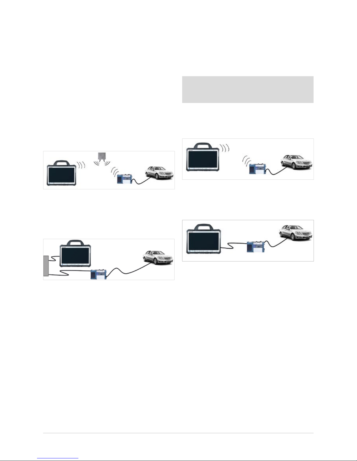
• WLAN workshop mode: Workshop IT infrastructure
with Access Point as a base station; both components
are integrated into the infrastructure via WLAN.
Figure 5: WLAN workshop mode
• WLAN workshop mode: Both components are integrated
into the infrastructure via cable. LAN workshop mode
is the alternative if no wireless network (WLAN) is available
or if the quality of the WLAN network is inadequate.
Figure 6: LAN workshop mode
Important: Please note that – in contrast to Star Diagnosis –
you require two LAN sockets and two LAN cables of corresponding lengths per workstation to operate the devices in
this mode. If you only have one LAN jack per workbay, we
recommend the use of a commercially available LAN hub/
splitter.
4.1.2 Service24h mode
XENTRY Kit 2 can be connected directly via LAN or WLAN
using the Service24h mode. This may be useful, for example, during use on the road or outside on your company’s
forecourt.
Note: You are not connected to the workshop network in
the Service24h network prole, i.e. you have no back-end
connection (e.g. to central servers for XENTRY Flash).
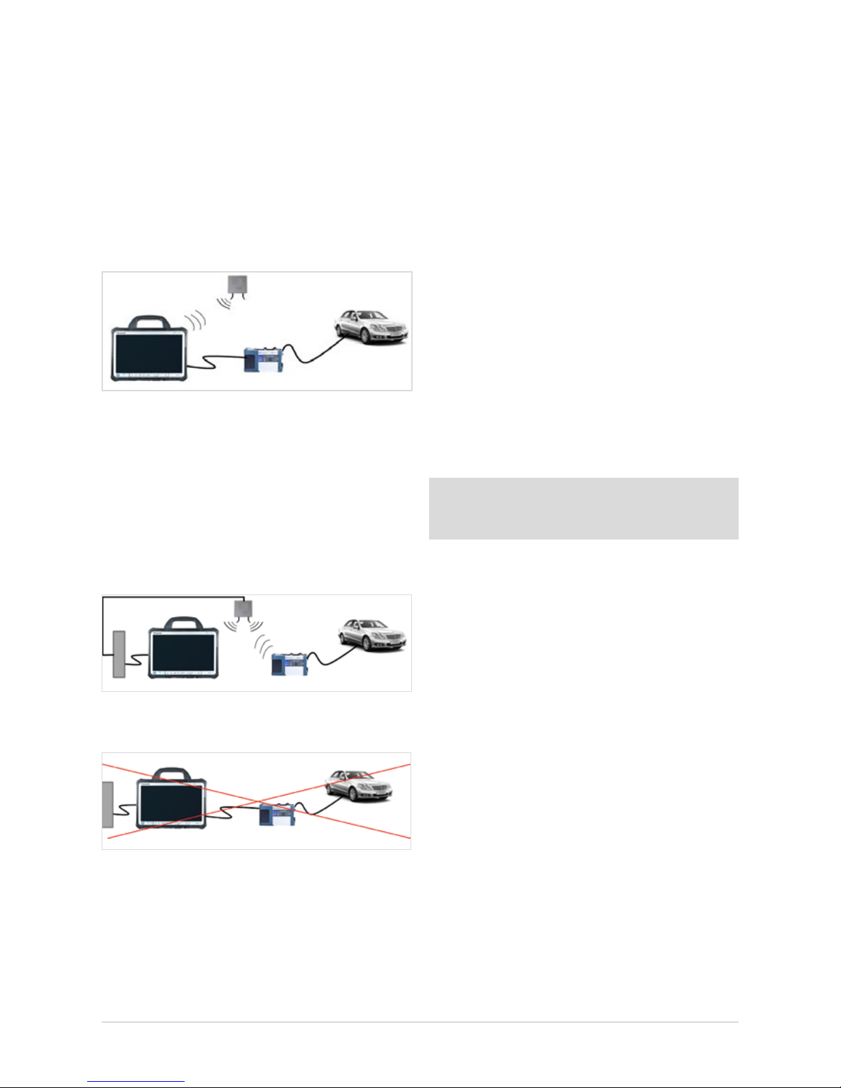
• Service24h WLAN mode: Direct wireless connection
between XENTRY Tab 2 and XENTRY Connect without
Access Point as a base station.
Figure 7: Service24h WLAN mode
• Service24h LAN mode: The devices are connected via
Service24h mode with a direct cable connection between
the XENTRY Connect and XENTRY Tab 2.
Figure 8: LAN Service24h mode
12
4.1.3 Cabled online mode
In the event that you require an online connection to backend systems, but you want to establish the connection
between XENTRY Tab 2 and XENTRY Connect independent
of the workshop infrastructure, a new mode is now available. It requires using the WLAN workshop mode and thereby
an online connection of the XENTRY Tab 2. To setup the
cabled online mode, connect the XENTRY Tab 2 and XENTRY
Connect to each other using an Ethernet cable and click on
the XENTRY Connect tile in XENTRY Control. This automatically congures thenew mode.
Figure 9: Cabled online mode
4.1.4 Mixed Operation
• WLAN and LAN combined
Workshop mode in mixed operation: E.g. XENTRY Connect
in the WLAN, XENTRY Tab 2 in the LAN. Devices are linked
to each other via the workshop network and are connected
to the back-end systems.
Figure 10: Combined WLAN and LAN
The following connection logic is not possible:
Figure 11: Connection mode not possible
The “serial connection” familiar from Star Diagnosis systems,
i.e. the connection of XENTRY Connect and XENTRY Tab 2 to
the workshop infrastructure via LAN and connection of the
XENTRY Tab 2 via LAN, is not possible.
4.2 Minimum technical requirements and restrictions
on use of a standard PC
A standard PC may be used as an operating and display
unit instead of the XENTRY Tab 2. You are entirely at liberty
to choose the PC manufacturer and model, but must observe
certain minimum requirements.
Minimum requirements:
Operating system: Windows 7 or Windows 8.1(recom-
mendation: Professional 32-bit)
Processor: 1.1 GHz Dual-Core
Hard disk: At least 30 GB available
RAM: 2 GB
USB ports: At least 2 x USB 2.0 (for external
BD drive) or integrated BD drive
Network: LAN and WLAN
Display: Recommended minimum size: 13.3”
Recommended minimum resolution:
1366*768 pixels
Virus scanner: Recommended
.net Framework version 4.0
Note: You will nd the current recommendations
for the minimum requirements of a standard PC in the
Mercedes-Benz After Sales Portal.
Restrictions on use of a standard PC:
• No XENTRY HMS 990 USB Measurement Technology
or chip card reader can be used; the product support
is also limited.
• All Windows updates must be installed independently and as
soon as possible (automatically is best) on the standard PC.
13
User Guide XENTRY Kit 2, XENTRY Kit MT 2, XENTRY Connect Daimler AG, Item No. 6511 9538 02, Last updated: 09/2014
5 Initial Startup and Configuration
Certain steps have to be run through on initial startup of the XENTRY Kit 2.
The HelpCard is also enclosed in the case as a quick guide for initial startup.
5.1 Brief overview of initial XENTRY system startup
1. Unpacking the devices: Remove the XENTRY Tab 2 and
the XENTRY Connect from the case. We recommend fully
charging the rechargeable batteries in the XENTRY Tab 2
and the XENTRY Connect once prior to initial startup.
To do this, connect the enclosed power supply units to
the relevant device. Initial startup can be started while
both devices are still charging. However, make sure that
the power supply is not interrupted at any time.
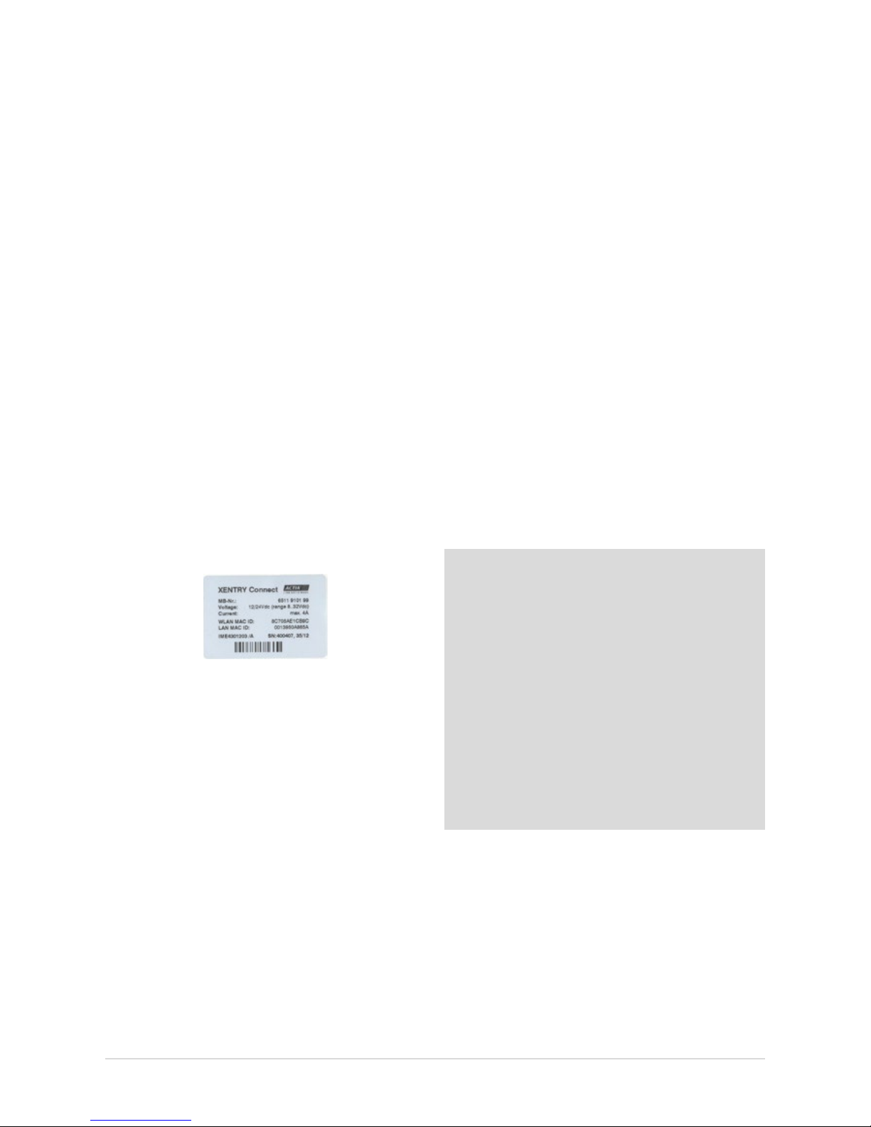
2. Enable the WLAN MAC addresses for the XENTRY Tab 2
and XENTRY Connect for your network. To do this, please
contact your IT administrator or IT service provider.
You will nd the MAC addresses on the adhesive labels
on the back of the XENTRY Tab 2 and XENTRY Connect.
Figure 12: Adhesive label with MAC addresses
Now ll out the network questionnaire that is enclosed
in the case together with your IT administrator.
Do not proceed with the initial startup until you have fully
completed the questionnaire! This allows you to avoid
additional work.
3. The software on the XENTRY Connect is pre-installed. The
standard XENTRY Connect language on delivery is always
English. You can change the language when connecting
the device to the XENTRY Tab 2 for the rst time.
4. XENTRY Control software is used to congure the
XENTRY Tab 2 and the XENTRY Connect for your
workshop network. CongAssist, which is integrated there,
guides you step-by-step through the process. CongAssist
opens automatically after starting XENTRY Control; if not,
it can be launched manually using the “Conguration”
menu.
5. Now, please order a StartKey and enter it into your
system so that you are able to use the XENTRY
Diagnostics/XENTRY DAS diagnostic software.
StartKeys are ordered through the already familiar tools
and channels; if necessary, inquire in your market.
Note: WIS/ASRA is only available via the central installations in on-line mode. This also ensures that you enjoy all of
the advantages of online operation on the diagnostic
systems, such as e.g. the latest documents
at all times. Of course, WIS/ASRA can still be accessed
from the XENTRY frame, so that transfer of the vehicle
context is always assured. If access to a central installation
is not possible or permitted, WIS/ASRA may also
be ordered as a WIS/ASRA standalone (i.e. oine including
updates via DVD) in exceptional cases. Use the standard
channels to order a WIS/ASRA StartKey in these situations.
However, orders can only be placed if a corresponding reason
is specied. With this variant, you receive the same monthly
WIS/ASRA DVD as for Star Diagnosis systems. Please
contact your market representative for further information.
14
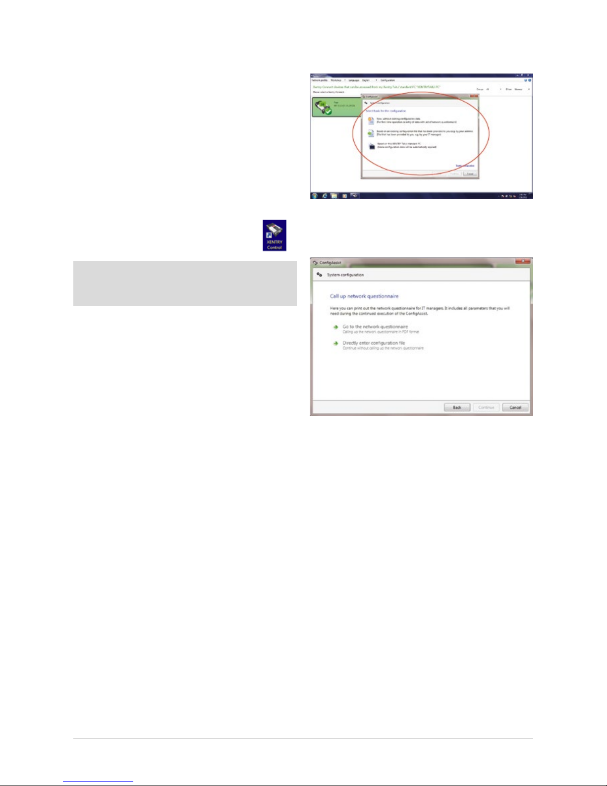
Figure 13: Start screen for conguration with CongAssist
The following screen will appear after you have selected
the conguration type:
Figure 14: Network questionnaire access screen
Here, you can call and print out the network questionnaire.
A printout of the network questionnaire can also be found in the
case. All important data on the workshop network, e.g. network
name and key, proxy settings, etc., can be documented on the
network questionnaire in advance. If necessary, ask the
IT administrator in your facility for the required data.
Then continue to follow the dialogs in CongAssist to congure both devices. The network questionnaire data are queried
step by step.
5.2 Congurationoftheoverallsystem
You have two conguration options: “Dialog-guided” (CongAssist) or by means of the “Expert dialog”. If you work with
xed IP addresses, please congure these via the DHCP
server. If, in exceptional cases, this is not possible, you
can congure it by means of the Expert dialog.
5.2.1 Conguration(dialog-guided,CongAssist)
You need the lled-out network questionnaire for the following conguration. Please have your completed
network questionnaire ready.
Start XENTRY Control using the desktop link
on your XENTRY Tab 2.
Note: If you are using a standard PC, a dialog for the deskband pop-up is shown here. Please conrm this dialog with
“Yes”.
CongAssist opens automatically after starting XENTRY
Control; if not, it can be called using the “Conguration”
menu. Check the external power supply to the XENTRY Tab 2
and XENTRY Connect.
Switch on the XENTRY Connect. To switch on the XENTRY
Connect, press any button on the XENTRY Connect operating
panel. Then, the message “Start XENTRY Connect?" appears
in the display. Conrm this message with the green tick. The
XENTRY Connect will start.
During the startup process for the XENTRY Connect, the
message “Device is starting” will appear in the display. Wait
until the XENTRY Connect startup process is complete and the
ready LED is green. During the initial start, this can take up to
10 minutes. Please follow the dialogs on the XENTRY
Tab screen.
The rst dialog in XENTRY Control oers you three selection
options for beginning the conguration:
1.) New, without any existing conguration data
for the initial startup.
2.) Based on an existing conguration le,
e.g. upon replacement.
3.) Based on this XENTRY Tab 2/standard PC,
e.g. with a new XENTRY Connect.
Click the option that best suits your case. If you do not have
any information on this, in the rst CongAssist dialog select
the option “New, without existing conguration data” for the
initial startup.
15
User Guide XENTRY Kit 2, XENTRY Kit MT 2, XENTRY Connect Daimler AG, Item No. 6511 9538 02, Last updated: 09/2014
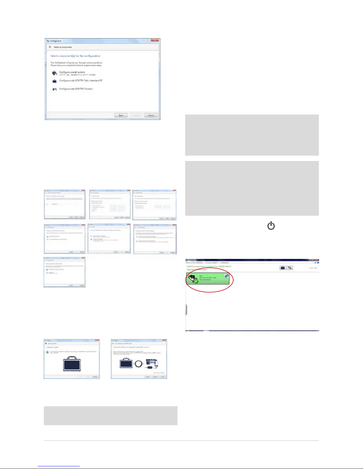
1. First, select the basis for the conguration.
Figure 15: Selecting the components for the conguration
In case of an initial startup, select “Congure overall sys-
tem”.
2. A series of numerous queries follows; please enter
the data and/or make the selections that your
IT administrator has noted on the network questionnaire.
Figure 16: Cong Assist dialog sequence for the initial startup
3. After the input has been entered, you can choose whether
the data should rst be saved in a le or immediately
applied to the XENTRY Tab 2 and the XENTRY Connect.
Select an option and proceed with the dialogs.
Figure 17: Apply conguration and successful conguration at completion of
Cong Assist.
Tip: Save the le so it can also be used for additional devices as a conguration le.
Now connect the XENTRY Connect with the XENTRY Tab 2
using the provided black Ethernet connecting cable, and
screw on the cable to the XENTRY Tab 2. On completion of
conguration, the XENTRY Connect display or the XENTRY
Control tile will show the message “Conguration success-
fully applied”.
The conguration wizard can be ended and the connection
between the two devices separated. To do this, simply disconnect the black Ethernet connecting cable from
both devices.
Note: If you work with xed IP addresses, we generally recommend that you set up a conguration via a DHCP server.
From an IT operations perspective, this is the most secure
way to ensure a sound and stable operating environment.
Details on DHCP can be found in the Connectivity Guide.
Note: If you do not use a DHCP server or, due to network
problems, you wish to assign static IP addresses for your
XENTRY Kit 2, you can also carry out the conguration via
XENTRY Control. In this case you must transfer the conguration to the XENTRY Connect by means of a USB memory
stick. To do this, save the conguration le on
a USB memory stick and insert it in XENTRY Connect.
Then check whether the “Ready” icon
appears in the
XENTRY Connect display and if the XENTRY Connect is shown
in green in XENTRY Control after about 10 seconds.
Figure 18: XENTRY Control Selection Screen
If yes, you may now use the XENTRY Connect to work on
the vehicle together with the XENTRY Tab 2. To do this, click
onto the green XENTRY Connect icon to connect to it.
If no, there are two possible remedies.
16
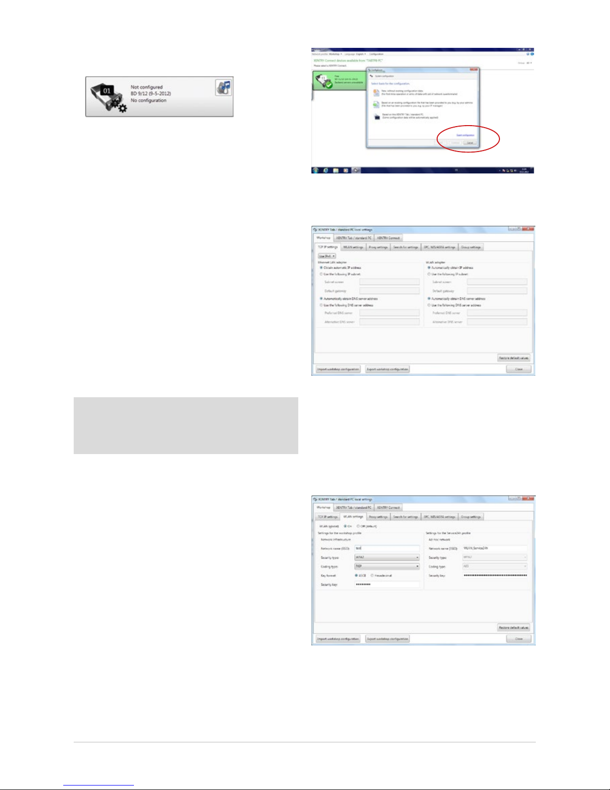
a) The XENTRY Connect icon is shown in gray in XENTRY
Control and the gears ash on the display:
Figure 19: XENTRY Control tile “Not congured”
In this case, repeat conguration as described in these
instructions. Note that CongAssist is now no longer
started automatically. Open CongAssist using the menu
bar in XENTRY Control in the “Conguration” menu item.
Please contact Diagnosis Support if a subsequent attempt
also fails.
b) XENTRY Connect does not appear any more in the
overview: in this case, check whether both devices are
set to the same network prole: workshop or Service24h
mode. This can be checked in XENTRY Control through
the menu
“Network prole” Service24h and by using
the gear button on the XENTRY Connect. If the XENTRY
Connect is still not displayed, then prior to reattempting
conguration the XENTRY Connect and the XENTRY Tab 2
must be connected directly using the Ethernet connecting
cable and Service24h mode must be set in each case.
Only then is it possible to perform conguration again
using CongAssist.
Note: After removing the black Ethernet connecting cable,
the devices are only connected if the WLAN is activated
and congured, i.e. if WLAN conguration has been executed in CongAssist.
Please contact Diagnosis Support if a subsequent attempt
also fails.
5.2.2 Expert mode initial startup
In contrast to the procedures described above, this initial
startup procedure is not guided and you must enter the
required data yourself. We only recommend using this
procedure if you have extensive technical knowledge and
have already congured such devices in the past. Keep your
workshop-specic network data ready, e.g. the IP address,
network name and key, as these are required to ll in the
screen. This section only explains the dierences between
expert conguration and initial startup using CongAssist.
The expert dialog is also called using the “Conguration”
menu item in the XENTRY Control software. Then click onto
the blue “Expert conguration” link at the bottom right in
CongAssist:
Figure 20: Accessing the conguration with the Expert dialog
The following window will open:
Figure 21: Expert dialog
The expert dialog is subdivided into the 3 “Workshop”,
“XENTRY Tab 2/standard PC” and “XENTRY Connect” tabs.
First switch to the “Workshop” tab at the top and then to the
“WLAN settings” panel. Make sure that the WLAN (global)
is set to “On”.
Figure 22: Expert dialog: WLAN settings
Fill in the elds required for your workshop. Enter the
individual values for your workshop in the proxy settings,
search for settings, EPC, WIS/ASRA settings and group
17
User Guide XENTRY Kit 2, XENTRY Kit MT 2, XENTRY Connect Daimler AG, Item No. 6511 9538 02, Last updated: 09/2014
settings tabs. If you would like to use groups, these must be
created in the group tab so that they can be subsequently
assigned to the XENTRY Connect devices.
This may be helpful if you use a number of XENTRY Connect
devices in your company or the company is subdivided into
dierent teams. The denition of groups oers a more clearly
arranged display in XENTRY Control.
Example: Team 1 Cars, Team 2 Trucks
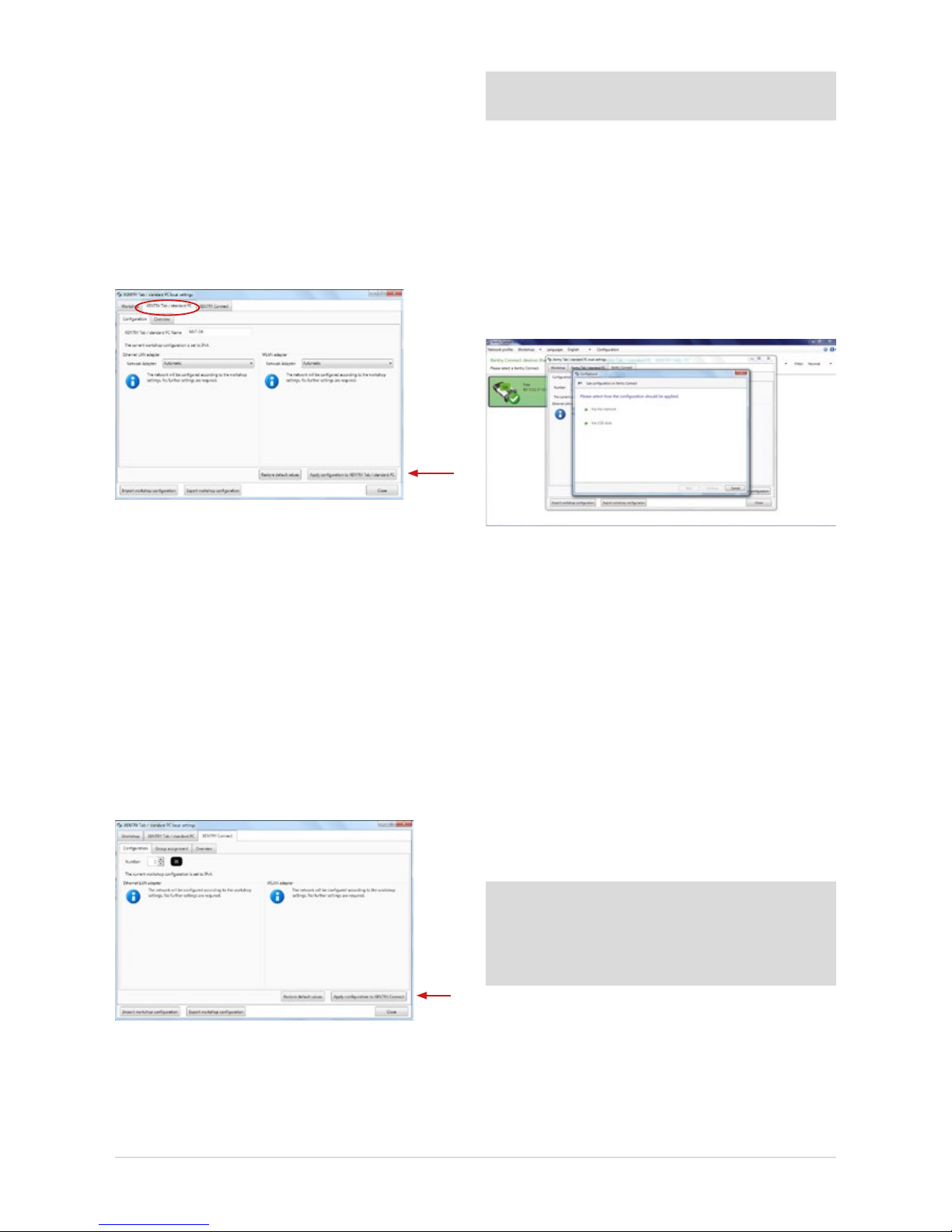
Now switch to the “XENTRY Tab 2 / standard PC” tab:
Figure 23: Expert dialog: Apply XENTRY Tab 2 conguration
Fill in the following elds in the “XENTRY Tab 2 / standard PC”
tab:
• The name of the XENTRY Tab 2 must be entered
(without blanks) in the “Conguration” tab
• An overview of the input data is displayed in the
“Overview” tab
• Finally, press the “Apply conguration to XENTRY Tab 2 /
standard PC” button
The following message appears: “Please wait while the
conguration is applied to the XENTRY Tab 2.” The message
“Conguration successfully applied” appears after a while.
Now switch to the “XENTRY Connect” tab:
Figure 24: Expert dialog: Apply XENTRY Connect conguration
Please enter the desired number of the XENTRY Connect in
the “Conguration” tab.
Important: Each number may only be assigned once in
your workshop!
• The groups previously dened for your workshop
operation in the “Workshop – groups” tabs can be
assigned to the XENTRY Connect. A list containing
the dened groups appears.
• An overview of the input data is displayed in the
“Overview” tab.
• Finally, press the “Apply conguration to
XENTRY Connect” button.
The following dialog will appear:
Figure 25: Expert dialog: Conguration type prompt
Here, you may select whether you want to carry conguration out “Via the network” (using the
Ethernet connecting cable) or “Via USB stick”.
“Via the network” means that conguration is carried out
using the Ethernet connecting cable by which the XENTRY
Tab 2 is connected to the XENTRY Connect.
“Via USB stick” means that conguration is carried out
by saving the conguration le to a USB stick, which has
to be inserted into the XENTRY Connect.
If you want to perform the conguration by means of a USB
memory stick, save the le onto the stick by clicking “Via
USB memory stick”; continue to follow the dialog prompts.
Note: The conguration le must be saved on the USB memory stick in the directory VCI_VIEW/cong; this directory
is automatically created by XENTRY Control. Please do not
change the name of the le. Otherwise,
the le cannot be read.
Now insert the USB memory stick into the XENTRY Connect.
The XENTRY Connect must be switched on. Then press the
“green check” and “red cross” buttons simultaneously. In
the display your are asked “Start conguration?", conrm
this with the 'green check-mark'. The conguration will be
initiated; the XENTRY Connect LED will ash green.
18
On completion of the conguration, you will see the message
“Conguration applied successfully” in the XENTRY Connect
display. Please remove the USB memory stick from the XENTRY
Connect. The conguration is now nished.
If you select “Via the network”, the message “Please connect
the XENTRY Tab 2 to the XENTRY Connect using the Ethernet
connecting cable” appears after clicking on “Continue”. Check
whether both devices are correctly connected via the Ethernet
connecting cable. The message “Conguration successful”
appears after a while. You are now nished conguring the
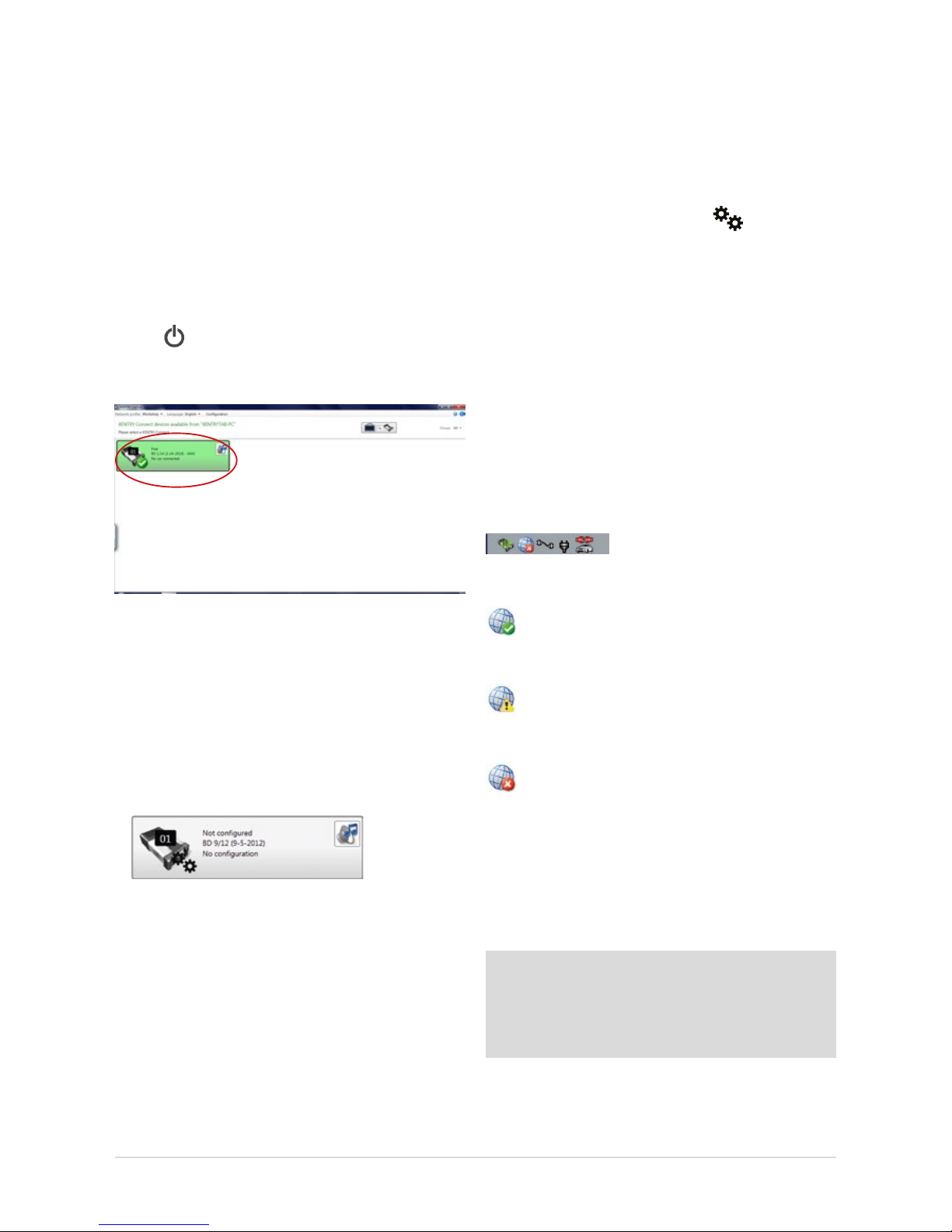
XENTRY Connect. Then restart both devices and wait until
both have completely booted. Check then if the “Ready”
symbol is shown on the display of the XENTRY Connect
and if the XENTRY Connect is shown in green after the
XENTRY Control software has been started:
Figure 26: XENTRY Control Selection Screen
If yes, you may now use the XENTRY Connect to work on the
vehicle together with the XENTRY Tab 2. To do this, click onto
the green XENTRY Connect icon to connect to it.
If no, there are two possible remedies.
a) The XENTRY Connect icon is shown in gray in XENTRY
Control and the gears are ashing on the display:
Figure 27: XENTRY Control tile “Not congured”
In this case, repeat conguration as described in
these instructions. Please contact Diagnosis Support
if a subsequent attempt also fails.
b) XENTRY Connect does not appear any more
in the overview:
In this case, check whether both devices are set to the
same network prole: workshop or Service24h mode.
If this does not remedy the problem, the XENTRY Connect
and the XENTRY Tab 2 must be connected directly using
the Ethernet connecting cable prior to reattempting
conguration, and Service24h mode must be set on each
device. This is carried out in XENTRY Control using the
menu
“Network prole” Service24h, and by using the
gear button on the XENTRY Connect , which you
press until the message “Switch to 24h mode?" appears
on the display. Conrm this message with the green tick.
Only then is it possible to perform conguration again.
Please contact Diagnosis Support if a subsequent attempt
also fails.
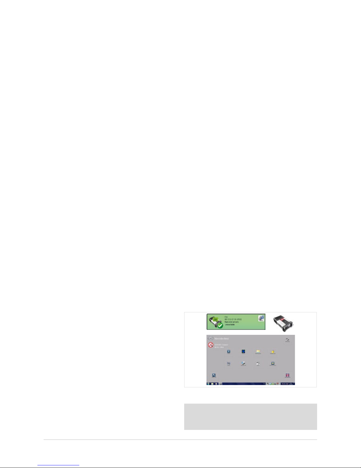
5.3 CheckingtheBack-endConnections
Whether the back-end connections (i.e. WIS, EPC, TIPS, VeDoc,
XSF, LogCollect/AQUA, XENTRY Flash Server) or Internet
connections are functioning correctly can be seen
at the bottom of the deskband when you are connected to your
XENTRY Connect.
Figure 28: Deskband
A globe with a green check-mark, indicating that all
back-end connections are accessible, appears in the
deskband.
If the globe is displayed with a yellow exclamation
mark, this means that only certain back-end
connections are available.
If no back-end connection is available, the following
icon will appear in the deskband:
In this case, please check whether the device is correctly
congured for your workshop and whether you are able to
establish an Internet connection at all. To test this, you can
open the XENTRY browser and e.g. call the After-Sales Portal
under favorites. If the homepage appears, you may assume
that the Internet connection is functioning correctly.
Note: As soon as XENTRY Tab 2 accesses the Internet for
the rst time, the Windows 7 updates are downloaded. This
can take a while. The XENTRY Connect is provided with the
Windows 7 updates via the “XENTRY Kit 2 Software Blu-ray
Disc”.
If no Internet connection is available, please check whether
the devices have been correctly congured for your
workshop. The data which you have input can be checked
19
User Guide XENTRY Kit 2, XENTRY Kit MT 2, XENTRY Connect Daimler AG, Item No. 6511 9538 02, Last updated: 09/2014
by calling up the menu in XENTRY Control: Conguration
Check Expert dialog. One further reason may be that
the XENTRY Connect and/or XENTRY Tab 2 have not been
enabled for your workshop network. In this case, ask your IT
manager / workshop network service provider.
5.4 Order StartKey
On completion of conguration, you must order the necessary StartKeys to be able to use the XENTRY system. The
StartKey enables you to use the XENTRY Diagnostics and
XENTRY DAS diagnostic applications. You also require an
additional StartKey to use WIS standalone. Please note that
the use of WIS standalone is only now approved in exceptional cases. Make sure that an Internet connection
is available and carry out the following steps:
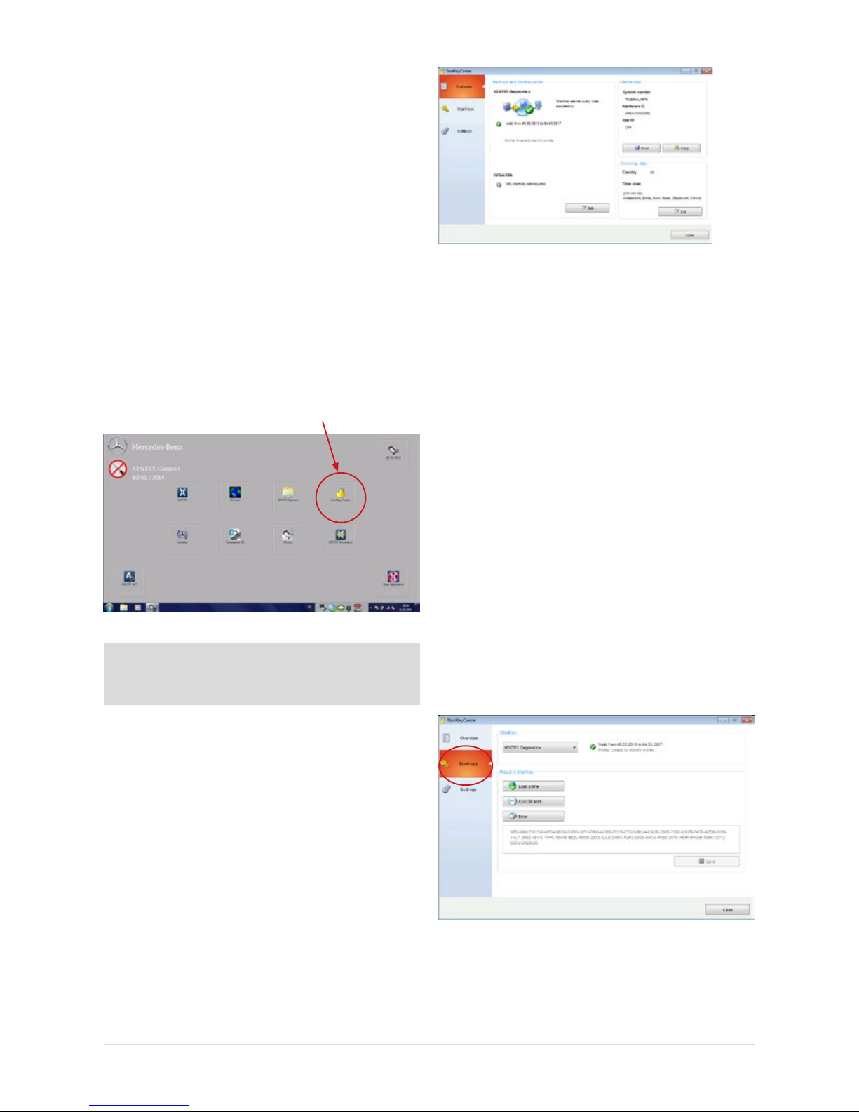
1. Connect to the XENTRY Connect. Start the StartKey Center
using the button on the adjacent Diagnosis desktop.
Figure 29: Diagnosis desktop on the XENTRY Connect
Note: A temporary StartKey is no longer available on the
XENTRY Connect! Please order the StartKey in a timely
manner.
2. Read out the HW ID and system number of your
XENTRY Connect in the “Overview” tab. You require this
information to order the StartKey.
You have the option of saving the values by means of
“Copy” and/or “Save” buttons to save the values and
make it easier for the StartKey order to read them in.
Figure 30: StartKey Center overview
3. We would like to point out our electronic ordering options
(LOP, LOT) to apply for permanent access authorization
(StartKey). Information on which ordering process is used
in your country (LOP, LOT or ordering through a central
national contact person), is available from the contact
person for access authorization/StartKeys at your
national company.
4. Now open the “StartKeys” tab. You now have three
options for reading the StartKey for XENTRY Diagnostics
into your system.
a) You save the attached le (which you received via email)
on a USB memory stick in the root directory, then insert
it in the XENTRY Tab 2 and read in the StartKey in the
StartKey Center from the USB memory stick.
b) Then open the StartKey Center and click on the “Load
StartKey online” button. The StartKey is then read-in
directly online. For this variant, you must make sure
that the XENTRY Connect has an Internet connection.
c) You manually enter the StartKey.
Figure 31: Screen for entering StartKeys
20
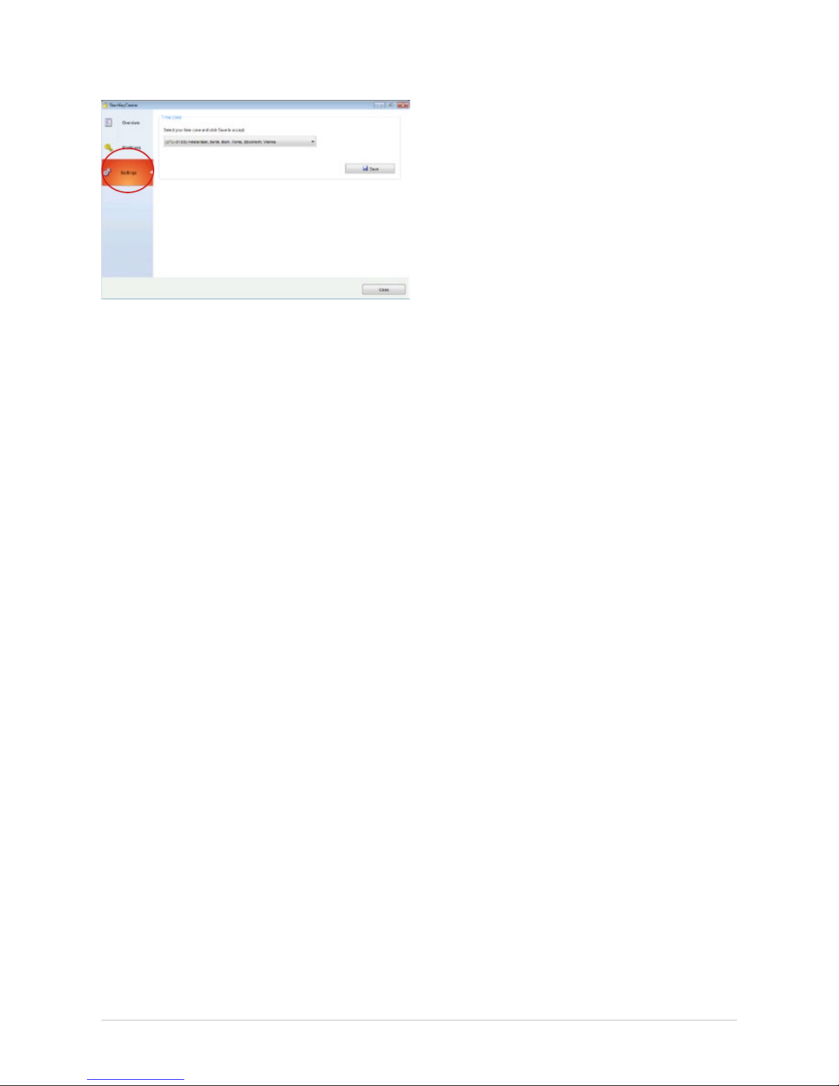
5. Then, specify your time zone in the “Settings” tab
and save them by means of the “Save”.
Figure 32: Settings screen in the StartKey Center
You may now start XENTRY Diagnostics. You can now also
use XENTRY Diagnostics in the Service24h mode.
21
User Guide XENTRY Kit 2, XENTRY Kit MT 2, XENTRY Connect Daimler AG, Item No. 6511 9538 02, Last updated: 09/2014
6 XENTRY Connect
As the successor to SDconnect, the XENTRY Connect oers
an autonomous PC core in addition to the multiplexer properties.
Figure 33: XENTRY Connect
The following points provide a brief overview of the properties
and performance features of the XENTRY Connect:
• The core element is a PC with an SSD as a robust storage
medium on which the diagnostic programs are executed.
• The power supply for the XENTRY Connect occurs:
- Directly through the vehicle’s diagnostic socket (OBD)
- Via the battery in the absence of an on-vehicle supply
- With the aid of an external power supply unit included
in the delivery scope
• The connection with the XENTRY Tab 2 is carried out:
- Wireless: via WLAN; a WLAN module is installed
- Cable-based: using the Ethernet connecting cable
included in the delivery scope
6.1 Technical Performance Features
Operating system: Windows Embedded Standard 7 (32-bit)
Processor:
B810 CPU (Core2Duo 2nd gen., 2x 1.6 Ghz)
RAM: 4 GB
Data storage: 256 GB SSD
Display size: 128x64 px
Battery operating
time:
40 minutes with 60% CPU load
USB interfaces:
2 x USB 2.0
Weight (incl. battery):
1.9 kg
Protection class: IP 54
Other interfaces:
WLAN interface
Warranty: 3.5 years (battery warranty: 6 months)
Number of batteries:
1
WLAN standard: IEEE 802.11 a/b/g/n 2.4 + 5 GHz
Certications: CE, UL, GOST-R, KCC, FCC, VCCI, WLAN
The XENTRY Connect is supplied with the WLAN module
deactivated in all non-certied countries. When operated in
these countries, we recommend the use of a “micro stick”
(e.g. D-Link DWA-131/D-Link DWA-121) to nevertheless
enable you to work in the WLAN. If the D-Link stick DWA131/D-Link DWA-121 is not available in your country, please
contact the Diagnosis User Help Desk.
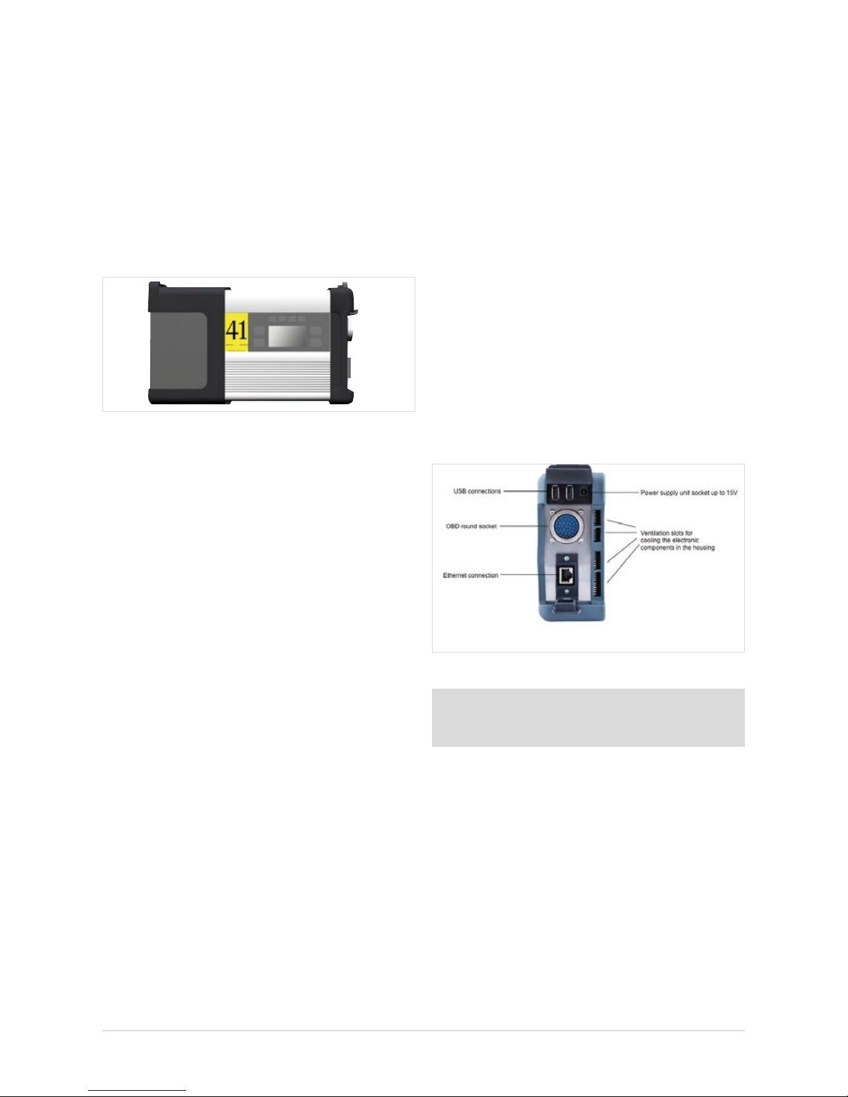
6.2 Interfaces on the XENTRY Connect
Figure 34: Connection options on XENTRY Connect
Note: Please make sure that the fan at the rear of the
XENTRY Connect is always free and that the XENTRY
Connect is not positioned lying on its fan in the vehicle.
6.2.1 Socket for the XENTRY Connect power supply unit
Used for the operation of a XENTRY Connect device via the
mains supply if it is not connected to a vehicle with the round
plug and not supplied by the vehicle battery. Only the power
supply unit included on delivery may be used.
6.2.2 USB Connections
The USB jacks are used to connect the Blu-ray drive from MoTelDis, the RS232 adapter for using the SBC ash box, for USB
sticks or other USB 2.0 devices approved by Daimler AG. The
power supply delivers max. 500 mA. The connection
of a keyboard or a mouse is not supported.
22
6.2.3 Connecting XENTRY Connect to the vehicle (cable)
A XENTRY Connect device can be connected to the vehicle
using various vehicle-specic connecting cables. The cables
are compatible with the current vehicle cables and are
connected to the XENTRY Connect using a so-called
push-pull mechanism.
Note: Please note that the XENTRY Connect must always
be supplied with sucient power when used in the vehicle.
When working on the vehicle, always connect an external
power supply to the vehicle (> 12.5 V).
6.3 XENTRY Connect operating panel
As is already familiar from SDconnect, the XENTRY Connect
oers a display and four buttons for operation. Two green
and two red LEDs for indicating the current operating status
are new.
Figure 35: XENTRY Connect operating panel and display
6.3.1 Button Lock on the XENTRY Connect
The XENTRY Connect is equipped with a button lock so that
it cannot be switched on unintentionally during transport or
daily operations. If you wish to switch the XENTRY Connect on,
press any button on the operating panel. The prompt “Start
XENTRY Connect?" then appears on the display. Conrm this
by pressing the green tick on the operating panel. The XENTRY
Connect starts after pressing the green tick.
Note: If the XENTRY Connect is stored for longer than
50 days without external supply voltage (connection to
a vehicle or external power supply unit), this will cause the
complete shutdown of the XENTRY Connect in order to
prevent a deep discharging of the battery. In this operating
state the display is switched o and the XENTRY Connect
device does not react any more to the pressing of a button.
A restart of the device and consequently the reactivation
of the display and keypad is accomplished by connecting
it to the power supply unit included in the delivery scope.
Recharge the device completely.
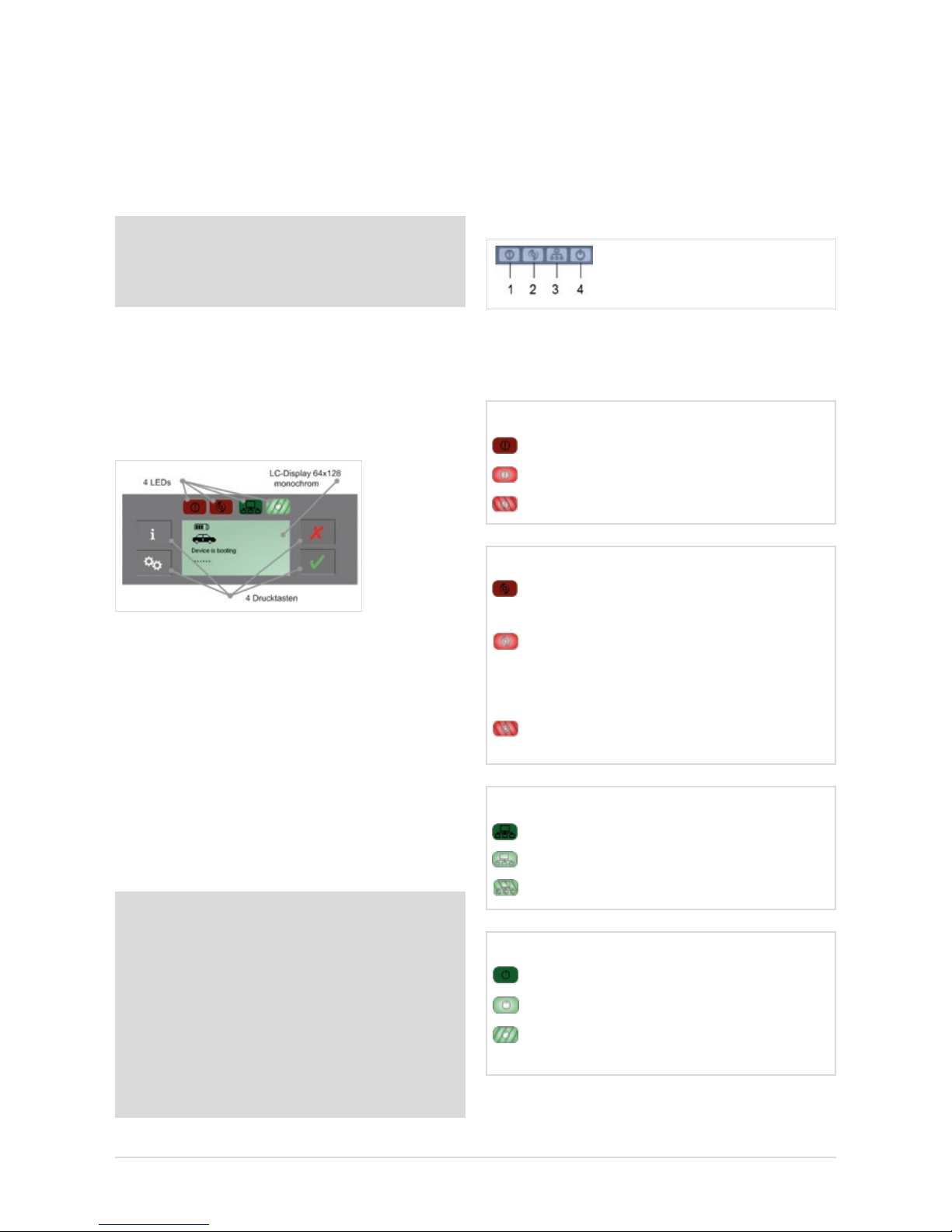
6.3.2 LEDs and Search Tone
To indicate dierent status and event information, the
XENTRY Connect is equipped with two green and two red
LEDs as well as an acoustic search tone. If the search tone
is activated, all LEDs ash simultaneously for the dened
time period of 10 seconds and a signal tone is sounded
on the device at the same time.
Depending on status (o, on, ashing), the LEDs have
dierent meanings; these are described in detail in the
following.
1 = Malfunction LED (red) 3 = Network LED (green)
2 = Occupied LED (red) 4 = Power LED (green)
Malfunction LED (red)
OFF No fault found
On Device fault found on the XENTRY Connect
Flashing
XENTRY Connect battery is almost empty
Occupied LED (red)
Network LED (green)
O No network connection available
On Network connection exists
Flashing
A network connection is being established
O XENTRY Connect is unused
and can be used
On XENTRY Connect is operating and cannot
be used (XENTRY Tab 2 is connected or an
independent process, such as an update,
is running)
Flashing
The XENTRY Connect is blocked by
a
XENTRY Tab 2 that is not currently connected.
Power LED (green)
O XENTRY Connect is switched o
On XENTRY Connect is operational
Flashing
XENTRY Connect is booting or
has not yet been congured
23
User Guide XENTRY Kit 2, XENTRY Kit MT 2, XENTRY Connect Daimler AG, Item No. 6511 9538 02, Last updated: 09/2014
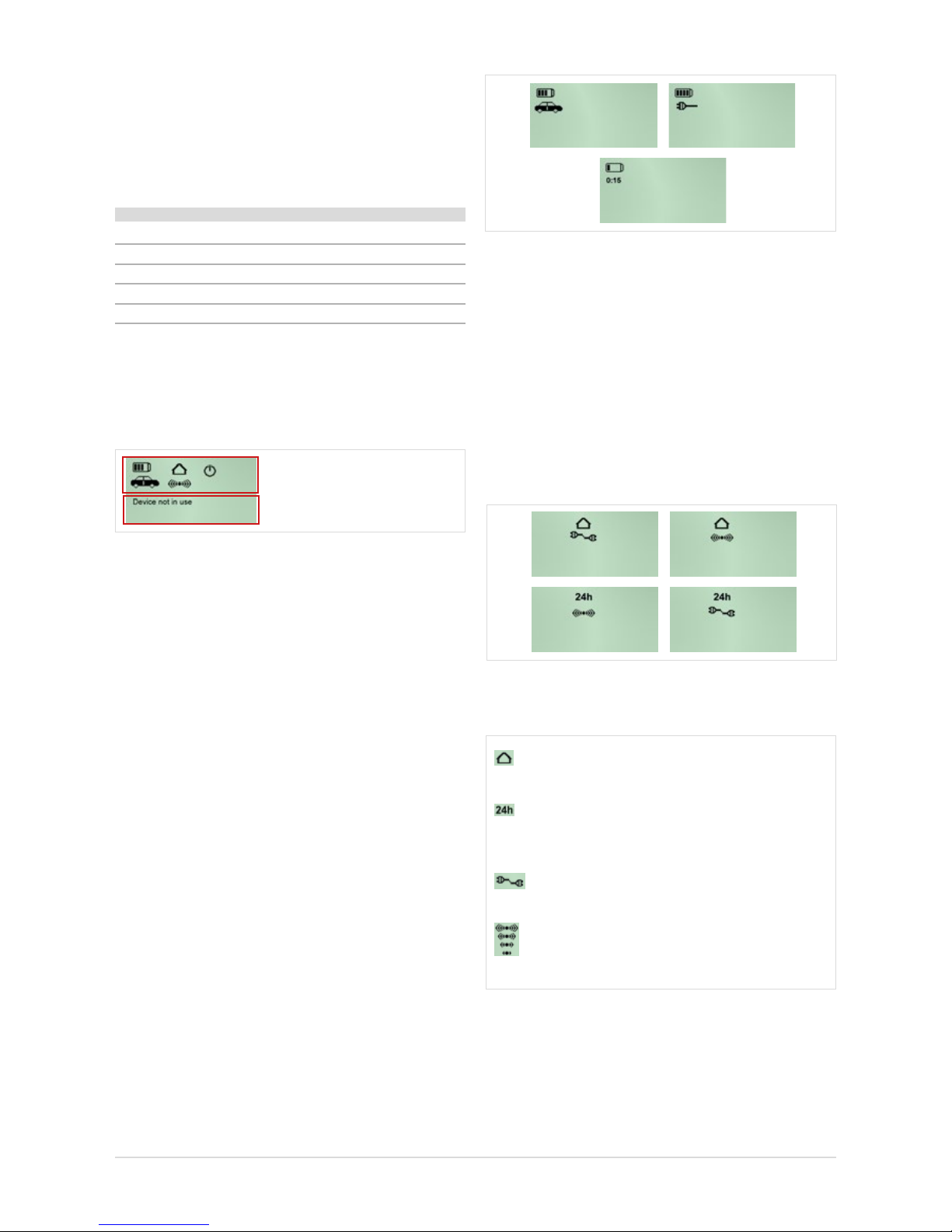
Figure 37: Battery statuses of the XENTRY Connect
Connection icon: connection status and quality
The house display and the 24h icon clearly indicate
which network prole is active.
The house symbolizes the workshop network. The 24h icon
shows that the devices are directly connected, e.g. for breakdown assistance. If a cable is displayed beneath,
this means that the connection has been established using
a cable. If the WLAN icon is displayed, this means that
the connection is wireless.
Figure 38: Network prole statuses of the XENTRY Connect
These symbols indicate the type and quality of connection.
stands for the workshop network prole (connection via a network)
stands for the Service24h network prole
(direct connection without network, similar
to the current road mode)
stands for a cable connection
(to the XENTRY Tab 2 or the workshop network)
stands for a WLAN connection: the number of
radio waves (one to four) shown in the relevant icon
represents the signal strength of the WLAN signal.
Figure 39: Key to icons: “Workshop”, “24h”, “LAN” and “WLAN”
Acoustic signal
Depending on the status of the device, the search tone
provides an acoustic signal which diers in terms of length
and repetition frequency. There are several statuses which
are indicated:
Status Sound
Startup process/switched on short 1x
No external power supply is currently present short
1x
Power supply switchover short 1x
Battery is almost empty short 3x
“Key Finder” activated 3x long
6.3.3 Display
The display is used to show all information that is relevant to
the user. The display is divided in an upper and lower section.
Upper section: Status icons
Lower section:
Additional information
Figure 36: Display of the XENTRY Connect
a) The upper half of the display serves to show status icons.
These are displayed permanently and updated as required.
They indicate the battery condition, type of connection,
and the operating state of the device.
b) The lower area is used for messages regarding the
properties, name and statuses of the device and
its connections as well as information to explain and
operate the available options.
6.3.4 Upper section of the XENTRY Connect display
Battery icon
The number of bars (zero to four) in the battery can be used
to determine the charge level of the rechargeable battery.
A vehicle or connector shown underneath indicates that there is a connection to the vehicle or another external power
supply, and that the rechargeable batteries are charging. If
there is no external power supply, however, the duration in
minutes until the XENTRY Connect automatically switches to
standby is located beneath the battery icon.
24
Operational status: Working status
The icons in the upper area of the display indicate whether a
XENTRY Connect is available or has already been occupied
by another XENTRY Tab 2, or whether a defect is present.
The XENTRY Connect is ready (the icon ashes while
the device is starting)
Device is occupied and currently operating.
Initial startup (icon ashes if the device is not con-
gured)
Defect/malfunction
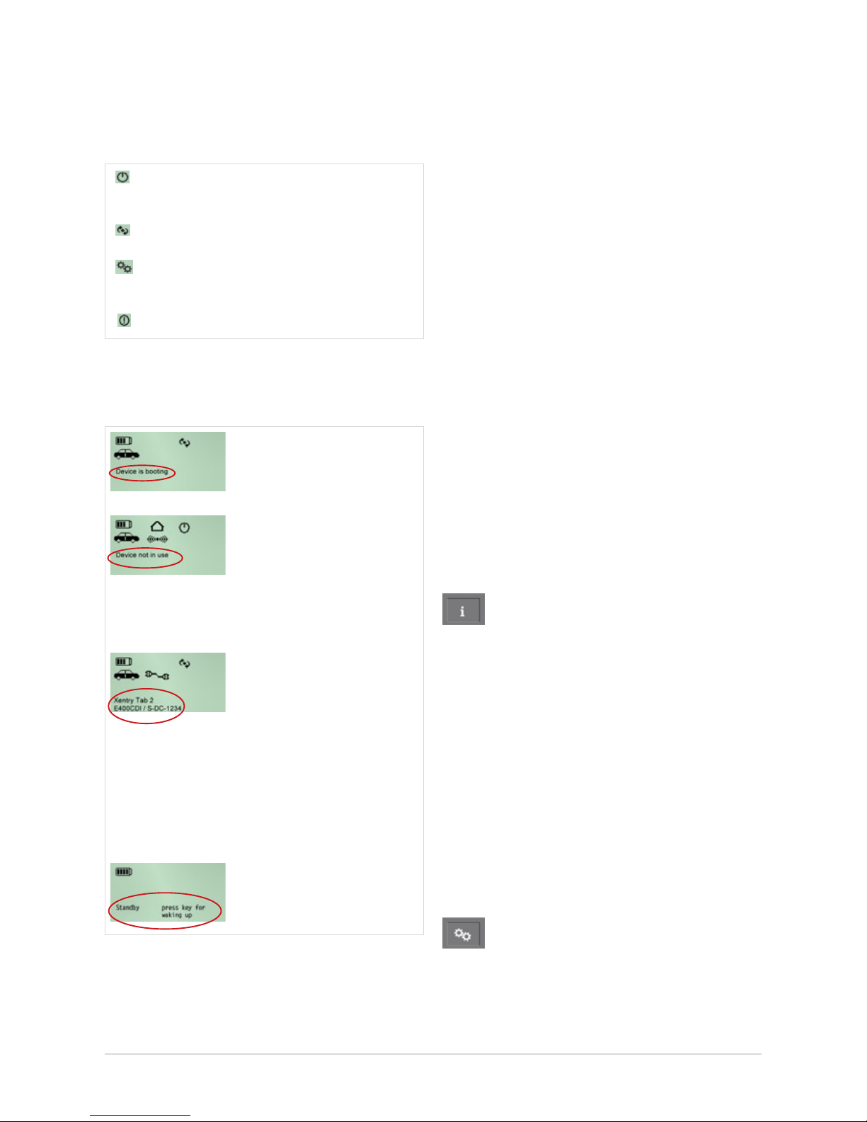
6.3.5 Lower section of the XENTRY Connect display
Examples
The “Device is booting” message appears during the booting
process.
With the OBD power supply
connected yet without acti-
ve application, the message
“Device is not in use” appears
and the currently installed BD
version is displayed.
If a power supply is connected
and an application is active,
a message generated by the
application is displayed. If
the device is connected to a
XENTRY Tab 2, the name of the
connected XENTRY Tab 2 is
shown above the name of the
application (in the example,
“XENTRY Tab 2 1”).
The device is not in use and is
set to standby.
Figure 40: Text and notes in the XENTRY Connect Display.
6.3.6 Background Illumination Statuses
The background illumination of the display has three operating states: ON, OFF and ashing.
• Background illumination ON indicates that the device has
recently been activated or a button has recently been
pressed.
• Background illumination OFF can be attributed to two
causes:
- If nothing is shown on the display at all any longer, the
device has no power supply. The rechargeable battery is
also empty or has been removed.
- When output is shown on the display (a), the XENTRY
Connect is either in standby or (b) no XENTRY Connect
buttons have been actuated within approx. 4 minutes, or
the information has not been updated/changed within
approx. 4 minutes.
• Background illumination FLASHING indicates that the
search tone is active.
6.3.7 Buttons of the XENTRY Connect
The XENTRY Connect oers the user the following four
buttons to operate the display and a button combination to
carry out updates.
Information button
This button guides you through an information menu and
displays the following information in succession:
• Diagnosis update version: Blu-ray Disc (BD) x/xx
• Vehicle battery voltage
• XENTRY Connect serial number
• Name of the connected XENTRY Tab 2
• Fault information
• Network information
- WLAN: MAC, DHCP status
- WLAN: IP, subnet
- WLAN: gateway, status
- WLAN: SSID, encryption
- LAN: MAC, DHCP status
- LAN: IP, subnet, gateway
Function buttons
This button can be used to access functions that are relevant
to the current device status; other functions will not be oe-
red (dynamic menu).
 Loading...