


EBS
Electronically controlled Brake system
in motor coaches
System and functional description
1. Edition
© Copyright WABCO 2003
Vehicle Control Systems
An American Standard Company
The right of amendment is reserved Version 001/07.01

EBS
Table of Contents
Page
1. Introduction / Advantages of EBS. . . . . . . . . . . . . . . . . . . . . . . . . . . . . . . . . . . . . . . . . . . . 3
2.System structure in buses
System structure 2-axle bus . . . . . . . . . . . . . . . . . . . . . . . . . . . . . . . . . . . . . . . . . . . . . . . . . . 4 WABCO EBS construction kit . . . . . . . . . . . . . . . . . . . . . . . . . . . . . . . . . . . . . . . . . . . . . . . . . 5 System variants . . . . . . . . . . . . . . . . . . . . . . . . . . . . . . . . . . . . . . . . . . . . . . . . . . . . . . . . . . . 6 Wiring diagram 2-axle bus . . . . . . . . . . . . . . . . . . . . . . . . . . . . . . . . . . . . . . . . . . . . . . . . . . . 7 Wiring diagram 3-axle bus . . . . . . . . . . . . . . . . . . . . . . . . . . . . . . . . . . . . . . . . . . . . . . . . . . . 8
3.Description of components
Brake signal transmitter 480 00. ... 0 . . . . . . . . . . . . . . . . . . . . . . . . . . . . . . . . . . . . . . . . . . . 9 EBS central module 446 135 ... 0 . . . . . . . . . . . . . . . . . . . . . . . . . . . . . . . . . . . . . . . . . . . . . 10 Proportional relay valve 480 202 ... 0 . . . . . . . . . . . . . . . . . . . . . . . . . . . . . . . . . . . . . . . . . . 11 3/2 relay valve 480 205 ... 0 . . . . . . . . . . . . . . . . . . . . . . . . . . . . . . . . . . . . . . . . . . . . . . . . . 12 Axle modulator 480 103 ... 0. . . . . . . . . . . . . . . . . . . . . . . . . . . . . . . . . . . . . . . . . . . . . . . . . 13
4.Description of EBS function
Function of the electro-pneumatic unit . . . . . . . . . . . . . . . . . . . . . . . . . . . . . . . . . . . . . . . . . 14 Function of pneumatic redundancy. . . . . . . . . . . . . . . . . . . . . . . . . . . . . . . . . . . . . . . . . . . . 14 Additional redundancy on the front axle . . . . . . . . . . . . . . . . . . . . . . . . . . . . . . . . . . . . . . . 14 Rear axle redundancy. . . . . . . . . . . . . . . . . . . . . . . . . . . . . . . . . . . . . . . . . . . . . . . . . . . . . . 15 Electrical / electronic structure . . . . . . . . . . . . . . . . . . . . . . . . . . . . . . . . . . . . . . . . . . . . . . 15 Control functions. . . . . . . . . . . . . . . . . . . . . . . . . . . . . . . . . . . . . . . . . . . . . . . . . . . . . . . . . . 16 Backup functions . . . . . . . . . . . . . . . . . . . . . . . . . . . . . . . . . . . . . . . . . . . . . . . . . . . . . . . . . 17 Halt brake, brake hold and release aid . . . . . . . . . . . . . . . . . . . . . . . . . . . . . . . . . . . . . . . . . 17
5.Error recognition and display
Error recognition . . . . . . . . . . . . . . . . . . . . . . . . . . . . . . . . . . . . . . . . . . . . . . . . . . . . . . . . . . 18 Error display . . . . . . . . . . . . . . . . . . . . . . . . . . . . . . . . . . . . . . . . . . . . . . . . . . . . . . . . . . . . . 19
6. EBS ”emergency modes” / EBS test types . . . . . . . . . . . . . . . . . . . . . . . . . . . . . . . . . . . 20
7. WABCO PC - Diagnosis . . . . . . . . . . . . . . . . . . . . . . . . . . . . . . . . . . . . . . . . . . . . . . . . . . . 21
Diagnostic equipment for WABCO EBS . . . . . . . . . . . . . . . . . . . . . . . . . . . . . . . . . . . . . . . . 22
Diagnostic Software EBS Euro . . . . . . . . . . . . . . . . . . . . . . . . . . . . . . . . . . . . . . . . . . . . . . 23
8.Parameter Setting
Parameter setting . . . . . . . . . . . . . . . . . . . . . . . . . . . . . . . . . . . . . . . . . . . . . . . . . . . . . . . . . 30
2

|
|
|
|
|
|
|
|
|
|
|
Introduction / Advantages of EBS |
EBS |
1. |
|
|
|
|
|
|
|
|
|
|
|
Introduction |
Increased brake safety |
The demands made on braking systems are increasing steadily. Therefore, the development and introduction of an electronic braking system (EBS) is a logical step.
EBS increases traffic safety through reduced stopping distance and improved brake stability. The full diagnosis and surveillance functions as well as the display of brake lining wear offer an effective fleet logistics.
Advantages of EBS
EBS reduces service costs considerably.
The electronic braking system has a lot of functions. The aim is to maximise braking safety at reduced costs, for instance by optimising wheel brake lining wear.
Setting pressure, according to wear criteria, to the front and rear axle results in uniform lining wear. Overall wear is minimised by making the load on all wheel brakes uniform. Moreover, servicing and lining replacement are done at the same time. This reduces down-time costs.
Depending on the vehicle utilisation profile and other factors, this also means considerable savings for the vehicle user. In terms of wheel brake service costs alone, a firsthand owner will save more money with an electronically braked bus than with a vehicle with a conventional braking system.
WABCO did not only take existing regulations into consideration while developing EBS. Top priority was given to safety and user advantages. This is why a vehicle with EBS can clearly do more than is required by law.
The high safety quality attributed to EBS is due to several factors:
Braking time is reduced through shorter response time and pressure build-up time of the brakes on the front and rear axle(s).
The improved ABS function increases vehicle stability when brakes are activated.
The components of the front and rear axle braking system and brake lining wear are monitored permanently.
The integrated ASR function also provides optimum vehicle stability and traction during start and acceleration.
3

2. EBS
System structure in buses
EBS braking system for buses with no attachment (4S/4M system)
10
9
11 |
8 |
1
|
2 |
|
12 |
|
|
6 |
13 |
|
|
|
|
7 |
4 |
3 |
14 |
|
|
||
|
|
|
5 |
Legend:
EBS components: |
Other components: |
||
1 |
EBS central module |
8 |
Compressor |
2 |
Brake signal transmitter |
9 |
Air dryer |
3 |
Proportional relay valve |
10 |
Four-circuit protection valve |
4 |
ABS solenoid valve |
11 |
Air reservoir |
5 |
Axle modulator |
12 |
Hand brake valve |
6 |
3/2 relay valve |
13 |
Relay valve FBA |
7 |
ABS sensors |
14 |
Brake cylinder |
4
|
|
|
|
|
|
|
|
|
|
|
System structure in buses |
EBS |
2. |
|
|
|
|
|
|
|
|
|
|
|
WABCO EBS construction kit
The design and structure of WABCO EBS allow high flexibility for vehicle manufacturers during system construction.
In terms of range
subsystem or full system
addition and cut-off redundancy
supply
|
Battery |
brake |
|
2P/1E-EBS |
|||
halt |
|||
|
|
||
AME |
= Axle modulator |
|
|
|
|||
BWG |
= Brake signal transmitter |
|
|
ECAS |
= Electronically Air Suspension System |
||
EMR |
= Electronically engine control |
|
|
PRV |
= Proportional relay valve |
|
|
REDV |
= 3/2 relay valve (redundancy valve) |
|
|
RET |
= Retarder |
|
|
RV |
= Relay valve |
|
|
S |
= Speed sensor |
|
|
V |
= Wear indicator |
|
|
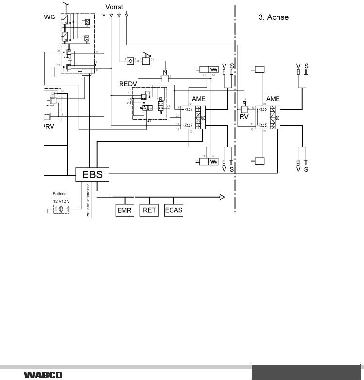
The EBS described here consists of a dual-circuit, purely pneumatic unit and a superimposed single-circuit, electro-pneumatic unit. This configuration is described as 2P/1E system.
The single-circuit, electro-pneumatic unit comprises a central electronic control device (central module), the axle modulator with integrated electronic unit for the rear axle, and, if necessary, the axle modulator for the third axle, a brake signal transmitter with two integrated
electrical interfaces
the most complex demands can, therefore, be met. To meet the vital needs of the vehicle owner, WABCO recommends an EBS with an individual pressure control unit on the front and rear axle, and which provides for pneumatic redundancies in all brake circuits.
third axle
desired value sensors and brake switches, as well as a proportional relay valve and two ABS valves for the front axle.
In terms of structure, the dual-circuit pneumatic unit basically corresponds to that of a conventional braking system. This unit serves as redundancy and only becomes active in case of electro-pneumatic circuit failure.
5
2. EBS
System structure in buses
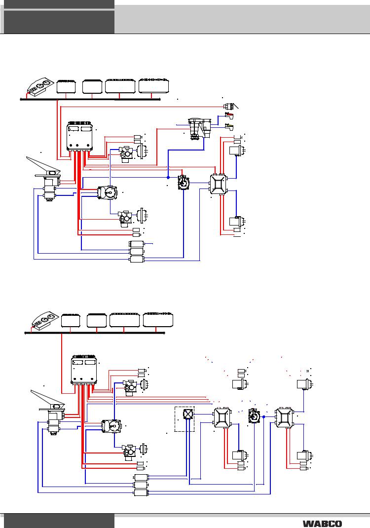
EBS 4S/4M in buses with optional trailer control
EngineMotor |
Rettarderr |
Gearboxet iebe |
Niveau- |
|
Level control |
|
|||
|
|
|
regelung |
|
Fahrzeug |
ten |
J 1939 |
|
ISO 11992 |
vehicle data busSAE J 1939 |
|
|
||
|
|
|
Luftbehälter |
|
|
|
|
air reservoir |
|
|
|
|
|
|
446 130 XXX 0 |
|
|
|
|
EPB 4S/4M IIII IIIIIIIII |
|
|
8 |
6 |
1 |
|
|||
|
|
|
||
|
|
|
7 |
|
2 |
4 |
|
|
|
|
|
|
|
|
9 |
|
|
|
|
|
3 |
|
|
|
|
|
|
|
|
4 |
|
|
7 |
|
|
8 |
|
|
Anhänger- |
|
|
trailer control |
|
|
steuerventil |
|
|
valve |
|
5
ISO 7638
 8
8
7
1Zentralsteuergerät EBS
2Bremswertgeber
1Central control unit EBS
3Prop. Relaisventil
2Brake signal transmitter
4ABS Magnetregelventil
3Proportional Relay valve
5Achsmodulator
4ABS Solenoid Control valve
6Anhängersteuerventil
5Axle modulator
7Splus Stabsensoren
6Trailer control valve
8Verschleißsensoren
7Splus rod sensor
9Redundanzventil
8Wear indicators
93/2 relay valve (redundancy valve)
7


 8
8
EBS 6S/6M in articulated buses
EngineMotor |
Retarder |
Gearboxtriebe |
Niveau- |
Level control |
|||
|
|
|
regelung |
vehicle data bus SAE J 1939 |
|
||
Fahrzeugdatenbus SAE J 1939 |
|
||
|
|
|
|
446 130 XXX 0 |
1 |
|
|
EPB 4S/4M IIII IIIIIIIII |
|
|
|
|
|
8 |
|
|
|
|
|
|
|
|
7 |
2 |
|
|
|
|
|
|
4 |
|
|
|
|
|
|
|
9 |
|
|
|
3 |
|
|
|
|
|
|
|
Optional |
|
|
|
4 |
|
|
|
7 |
|
|
|
8 |
1Central control unit EBS
1Zentralsteuergerät EBS
2Brake signal transmitter
2Bremswertgeber
3Proportional Relay valve
3Prop. Relaisventil
4ABS Solenoid Control valve
4ABS Magnetregelventil
5Axle modulator
5Achsmodulator
63/2 relay valve (redundancy valve)
6Redundancyredundanzventilvalve
7Splus rod sensor
7Splus Stabsensoren
8 |
|
Wear indicators8 |
|
Verschleißsensoren |
|||||||||||||||||||
9 |
|
Relay valve 9 |
|
Relaisventil |
|||||||||||||||||||
|
|
|
|
|
|
|
|
|
|
|
|
|
|
|
|
|
|
|
|
|
|
||
|
|
|
|
|
|
|
|
|
|
|
|
|
|
|
|
|
|
|
|
|
|
||
|
|
|
|
|
|
|
|
|
|
|
8 |
|
|
|
|
|
|
|
|
|
8 |
||
|
|
|
|
|
|
|
|
|
|
|
|
|
|
|
|||||||||
|
|
|
|
|
|
|
|
|
7 |
|
|
|
|
|
|
|
7 |
||||||
|
|
|
|
|
|
|
|
|
|
|
|
|
|
|
|
|
|
||||||
|
|
|
|
|
|
|
|
|
|
|
|
|
|
|
|
|
|
|
|
|
|
|
|
|
|
|
|
|
|
|
|
|
|
|
|
|
|
|
|
|
|
|
|
|
|
|
|
|
|
|
|
|
|
|
|
|
|
|
|
|
|
|
|
|
|
|
|
|
|
|
|
|
|
|
|
|
|
|
|
|
|
|
|
|
|
|
|
|
|
|
|
|
|
|
|
|
|
|
|
|
|
|
|
|
|
|
|
|
|
|
|
|
|
|
|
|
|
|
|
|
|
|
|
|
|
|
|
|
|
|
|
|
|
|
|
|
|
|
|
|
|
|
|
|
|
|
|
|
|
|
|
|
|
|
|
|
|
|
|
|
|
|
|
|
|
|
|
|
|
|
|
|
5 |
5 |
6 |
|
|
|
|
|
|
|
|
|
|
|
7 |
|
|
|
7 |
|
8 |
|
|
|
8 |
6

System structure in buses
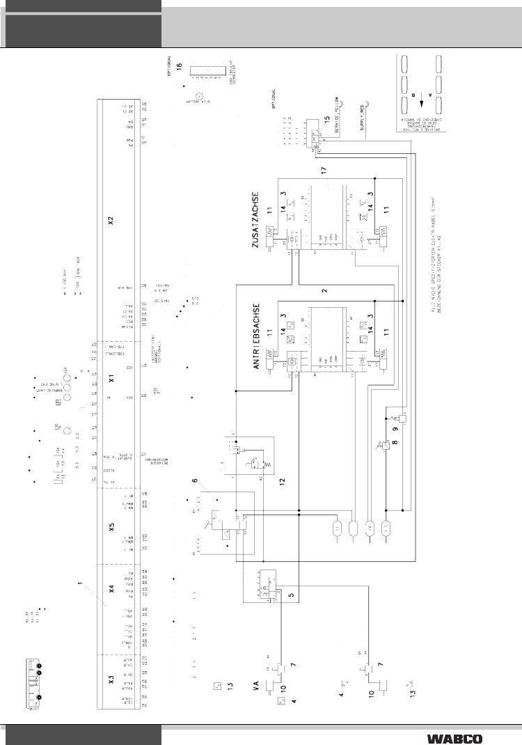
Wiring diagram 841 801 701 0: Dual-axle bus (4S/4M)
EBS 2.
7
2. EBS
System structure in buses
Wiring diagram 841 801 702 0: Three-axle bus (6S/6M)
8
|
|
|
|
|
|
|
|
|
|
|
Description of components |
EBS |
3. |
|
|
|
|
|
|
|
|
|
|
|
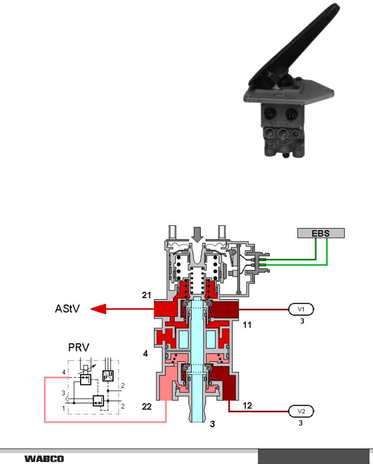
Brake signal transmitter 480 001/ 002 ... 0
The brake signal transmitter is used to produce electrical and pneumatic signals, and to increase and decrease the air pressure of the electronically controlled braking system. The device has a dual-circuit pneumatic and a dual-circuit electrical structure. Actuation start is recorded electronically by a double switch. The operating tappet’s route is controlled and transmitted as pulse-width modulated electrical signal. Further pneumatic redundancy pressure is delivered in circuits 1 and 2. The pressure in the second circuit is retained slightly in the process. In case of (electrical or pneumatic) failure of a circuit, the other circuits remain functional.
Depending on bus type, the brake signal transmitter is actuated via a running plate (480 002 ... 0) 0) or via a push pedal using the tappet (480 001 ... 0).
How it works:
9
3. EBS
Description of components
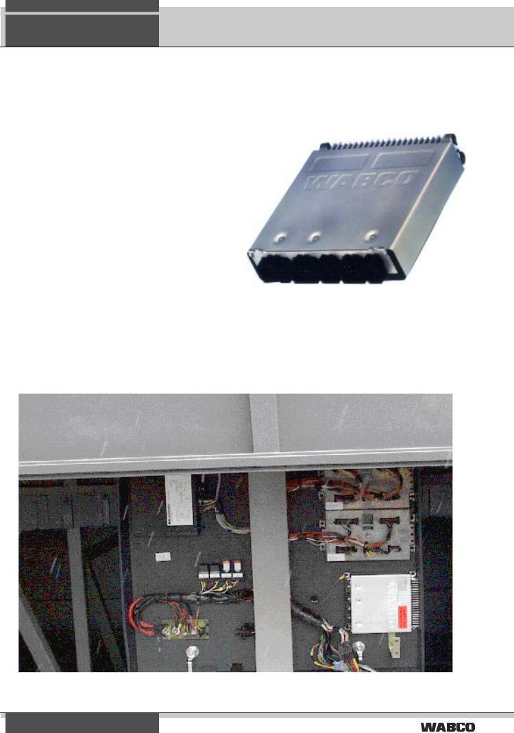
EBS central module 446 135 ... 0
The central module is used to control and monitor the electronically controlled braking system. It determines the vehicle’s nominal delay from the signals received by the brake signal transmitter. The nominal delay and the wheel velocity measured by the speed sensors are input signal for the electro-pneumatic control unit, which uses it to calculate nominal pressure values for the front axle and rear axle(s). The front axle’s nominal pressure value is then compared with the measured actual value, and any existing deviations corrected with the help of the proportional relay valve. Moreover, the wheel velocity is evaluated so that in case of locking, an ABS control can be carried out by modulating the braking pressure in the brake cylinders. The central module exchanges EBS system bus related data with the axle modulators.
The central module communicates with other systems (engine control unit, retarder, display unit, etc.) via the vehicle data bus in accordance with SAE J 1939.
KOM-integrated central unit:
10
 Loading...