

Mercedes-Benz 603, 602 Service Manual
Mercedes-Benz
Mercedes-Benz of North America, Inc. . Montvale, NJ 07645

Q
Mercedes-Benz of North America, Inc., 1991
All rights reserved. Reproduction by any means, electronic or mechanical, including photocopying, recording, or by any information storage and retrieval system
or translation in whole or part is not permitted without
written authorization from the publisher.
Published by Mercedes-Benz of North America, Inc.
Printed in U.S.A.
Part number LZ S-2517-091

This service manual is the product of existing technical publications. Special care has been taken
to provide accurate information on removal, disassembly, inspection, installation, and adjustment
procedures, together with the necessary technical data for the particular job.
The material in this manual is divided according to the Mercedes-Benz Component Group System
as outlined on the GROUP INDEX page. This page will quickly direct the reader to the Major
Component Group. Each Major Component Group begins with a JOB INDEX listing all jobs within
that group.
Mercedes-Benz of North America, Inc. recommends that repairs to, and maintenance of
Mercedes-Benz automobiles be performed by
trained Mercedes-Benz personnel
at authorized
Mercedes-Benz dealerships.
The information contained in this special publication is ordinarily issued by Mercedes-Benz of
North America, Inc., in conjunction with supplementary service literature and special tools supplied
only
to its authorized dealers. The repair and maintenance procedures outlined herein are
intended for use by
trained Mercedes-Benz service and dealership personnel.
This manual
can also be useful for Mercedes-Benz owners in diagnosing vehicle systems and performing
repairs.
Supplementary service literature will not be provided with this publication, but may be
contained in reprints of this service manual.
Please note that this manual has been compiled from various sources, some of which cover
models other than the subject of this book.
Always refer to the engine and vehicle identification
table for model and component information.
Special tools required in performing certain service jobs are identified in the manual and are
recommended for use.
Any part numbers given are only used for identification and easier
differentiation between individual components, and are not intended for ordering purposes.
If your Mercedes-Benz model differs from the specifications contained in the manual you select,
consult your authorized Mercedes-Benz dealer.
All procedures, illustrations and specifications contained in this manual were based on the latest
information available at the time of publication. All rights are reserved to make production, design
and specification changes at any time, without notice and without obligation to give notice. Any
such changes will not be contained in this manual.
Caution!
The proper performance of service and repair procedures is essential for both the safety of the
mechanic and the safe and efficient operation of the vehicle. The use of incorrect service
procedures and tools may greatly increase the risk of personal injury and render the vehicle
unsafe. The procedures in this manual are described in such a manner that the service may be
performed safely and accurately.
However, it is a general assumption that the reader is familiar with basic automotive repair
procedures and Mercedes-Benz vehicles. You should not attempt to use this manual if this is not
the case.
Mercedes-Benz of North America, Inc. assumes no liability for any damage to person or property
caused by the utilization of this publication to effect maintenance or repair work on Mercedes-Benz
automobiles.
MERCEDES-BENZ OF NORTH AMERICA, INC.
Service and Parts Literature
Group
Index
General, Technical Data
00
Crankcase
and
Cylinder
head
01
Crankshaft Assembly
03
ngine Timing, Valvetrain
05
Diesel Injection
System
07.1
Air Intake System - Air Filter, Turbocharger
09
elt Drive
13
Intake and Exhaust Manifolds, mission Control System
14
Electrical System, Preglow
15
ngine Lubrication System
18
ngine Cooling System
20
Engine Suspension
22
Accelerator Control
30
Fuel Tank and Lines
47
Exhaust System
49

General, technical data
00

General,
technical
data
00
Job No.
Instructions for use of service manual
. . . . . . . . . . . . . . . . . . . . . . . . . . . . . . . . . . . . . . .
00 - 005
Engine and vehicle identification . . . . . . . . . . . . . . . . . . . . . . . . . . . . . . . . . . . . . . . . . . . .
-
010
Vehicle identification number locations
. . . . . . . . . . . . . . . . . . . . . . . . . . . . . . . . . . . . . . .
-
015
Technical data . . . . . . . . . . . . . . . . . . . . . . . . . . . . . . . . . . . . . . . . . . . . . . . . . . . . . . . .
-
020
Instructions for use of
servic
00-005
Complete Service Manual coverage for late
model year Mercedes-Benz vehicles requires
four individual manuals:
Service Manual, Engine
Service Manual, Chassis and Body
Service Manual, Automatic Climate Control
Electrical Troubleshooting Manual
Throughout these manuals, the vehicles are
identified by their chassis and engine numbers.
These numbers are made up of the first six digits
of the respective serial number. For the actual
location of chassis and engine numbers, see
page
00-015/l.
In cases where the repair
instructions apply to all versions, only the first
three digits of the respective number are
referenced.
For example, chassis 124 applies to all 124
models. However, chassis
124.128
would apply
only to model 3000 2.5 Turbo.
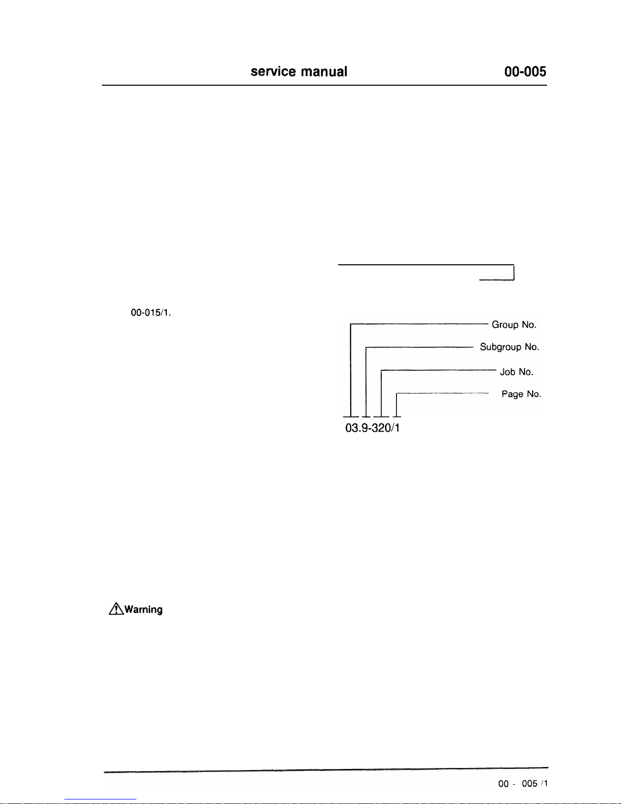
Location of specific repair instructions
First locate the Group No. in the Group Index.
Individual groups are separated by an easily
visible dividing page, which is followed by the job
index page. The exact job required is found in
the job index. The initial page of a typical job
description appears as follows:
03-320 Installation of Crankshaft
Job Title appears on
same line as Group
No.
03.9-320/l
Technical data, tightening torques and tools are
listed at the beginning of each job.
All dimensions are in metric units unless
otherwise indicated. Any part numbers given are
only used for identification and differentiation
between individual components, and are not
intended for ordering purposes.
Special Instructions
AWarning
Appears throughout service instructions indicating the possiblity of personal injury
if procedures are not followed.
Caution!
Indicates possible equipment or vehicle damage if procedures are not followed.
Note
Provides helpful information for the described procedure.
Installation note
Provides detailed information during assembly.
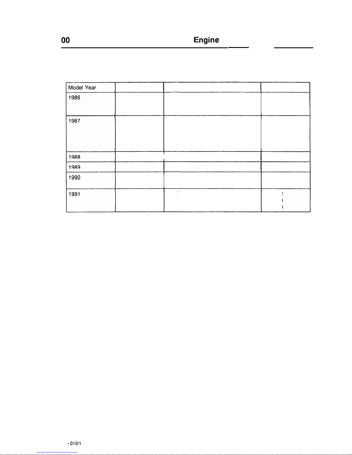
00
ngine
and vehicle identification
Model
I
Sales designation
I
Engine
201.126 190D2.5
602.911
126.125
300
SDL
Turbo
(Federal)
603.961
126.125
300
SDL
Turbo
(California)
603.961
201.126
190 D
2.5
602.911
201.128 190 D
2.5
Turbo
(Federal)
602.961
124.133
300 D Turbo
603.960
124.193
300TD
Turbo 603.960
126.125
300 SDL
Turbo 603.961
201.126
I
190 D 2.5
(Federal)
I
602.911
201.126
I
190 D 2.5
(Federal)I602.911
124.128
300
D
2.5
Turbo
(Federal)
602.962
126.135
350
SDL
Turbo
(Federal)
603.970
124.128
300
D
2.5
Turbo
(Federal)
602.962
126.134
350
SD
Turbo
(Federal)
603.970
126.135
350
SDL
Turbo
(Federal)
603.970
00 -
010/l
hick
identification number locations
00
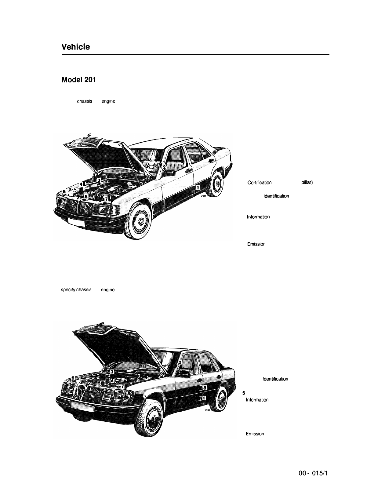
Model
201
When ordering spare parts, please
specify
chassrs
and
engine
numbers.
Model
124
When ordering spare parts, please
specify
chassis
and
engine
numbers.
1
Certrfication
Tag (left door
pillar)
2 Identification Tag (left windshield post)
3 Vehicle
Identificatron
No.
4 Engine No.
5 Body No. and Paintwork No.
6
InformatIon
Tag
California version
Vacuum line routing for emission
control system
7
Emrsslon
Control Tag
1 Certification Tag (left door pillar)
2 Identification Tag (left window post)
3 Vehicle
Idenkficatron
No.
4 Engine No.
5
Body No. and Paintwork No.
6
lnformatron
Tag
California version
Vacuum line routing for emission
control system
7 Emission Control Tag
8
Emrssron
Control Tag
Catalyst Information
00 -
015/l
Vehicle identification
number
locations
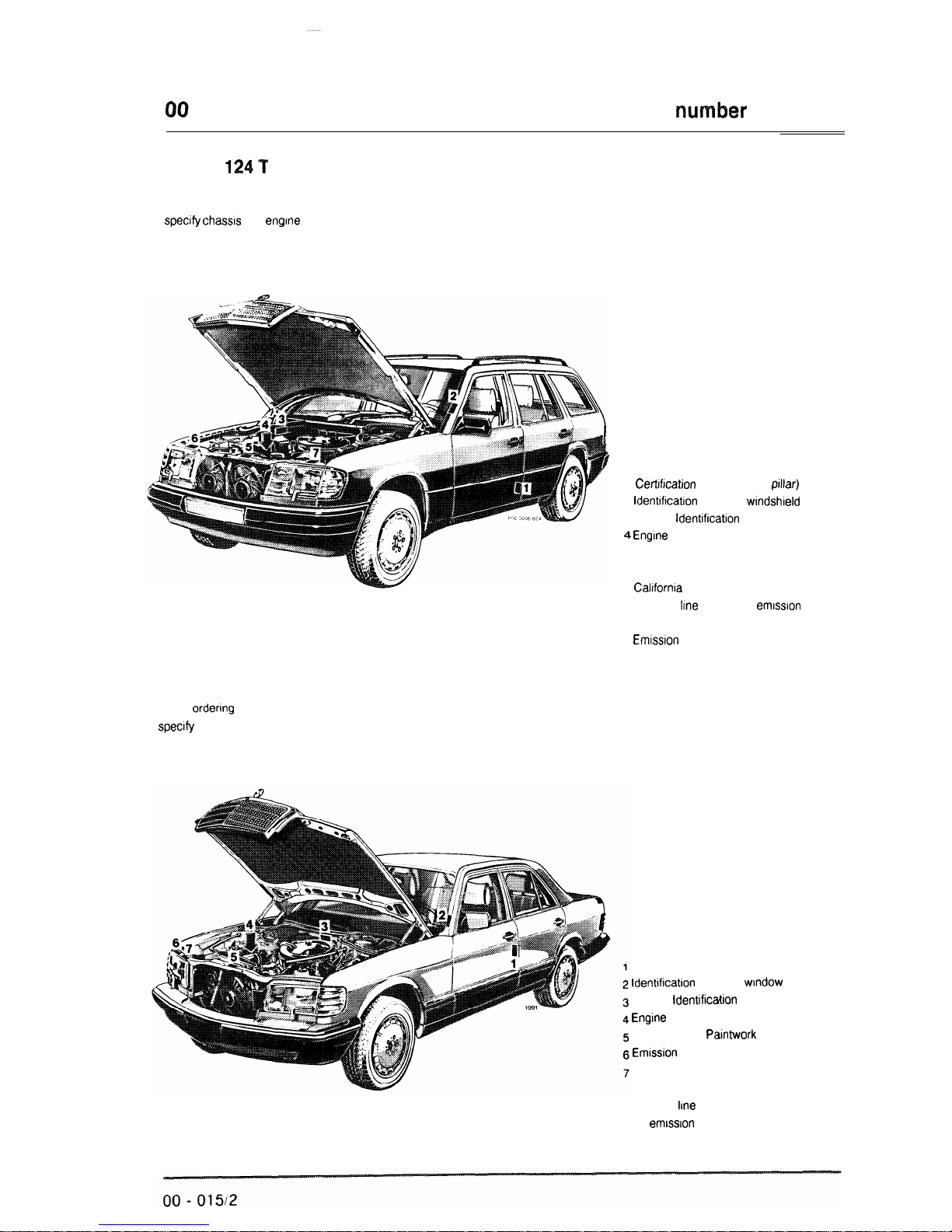
Model
124
f
When ordering spare parts, please
specify chassrs
and
engine
numbers.
1
Certrfication
Tag (left door
prllar)
2
ldentrftcatron
Tag (left
wrndshreld
post)
3 Vehicle
ldentifrcatron
No.
4
Engine
No.
5 Body No. and Paintwork No.
6 lnformatron Tag
Caltfornia
version
Vacuum
line
routing for
emrssron
control system
7
Emrssron
Control Tag
Model
126
When
ordenng
spare parts, please
specrfy
chassis and engine numbers.
Certification Tag (left door pillar)
ldentlficatron
Tag (left
wrndow
post)
Vehicle
ldentrfication
No.
Engrne
No.
Body No. and PaMwork No.
Emrssron
Control Tag
lnformatron Tag
California version
Vacuum
lrne
routing
for
emrssron
control system
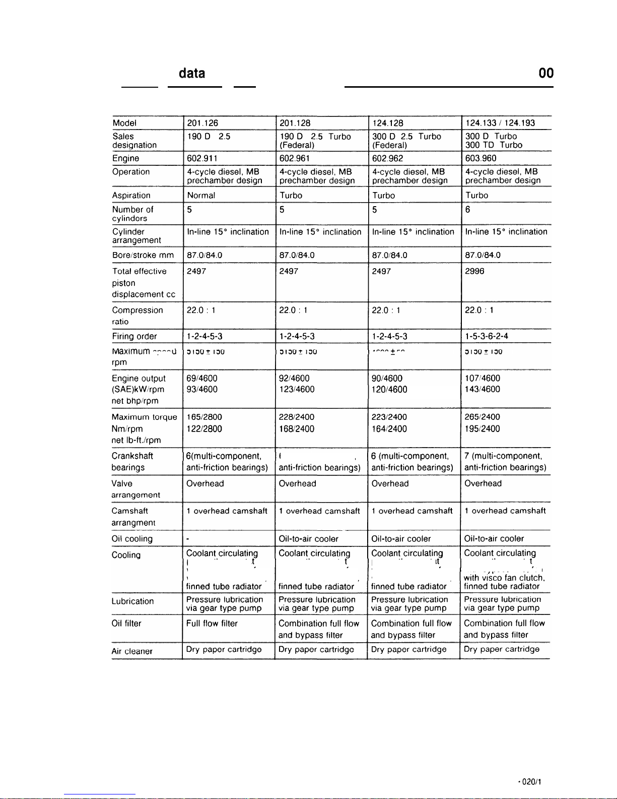
Technical
data
Diesel engines
axlmum spee
G(multi-component, 6 (multi-component,
pump, thermosta pump, thermosta
with bypass line, fan with bypass line,
fan
with
visco fan clutch,
with
visco fan clutch,
4600t 50
120/4600
pump, thermosta
pump, thermosta
with bypass line, fan
with
bypass line, fan
with visco fan clutch,
00 -
020/l
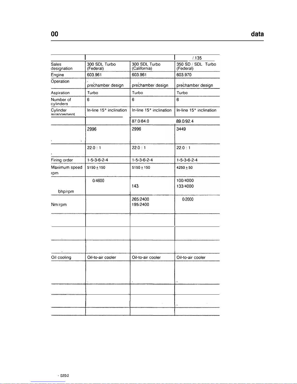
00
Technical
data
Gasoline engines
Model
i
126.125
1126.125
1
126.134
I.135
4-cycle diesel,
MB
4-cycle diesel,
MB
4-cycle diesel,
MB
arranqemen
Bore/stroke mm
I
87.0184.0
I
87.Oi84.0
I
89.0192.4
Total effective
piston
displacement cc
2996
2996
Compression
ratio
Engine output
(SAE)kW/rpm
net bhp/rpm
11
O/4600 1071’4600
14814600
143)
4600
Maximum torque
Nmirpm
net lb-ft./rpm
27312400
20112400
265/2400
195/2400
3 1
o/2000
22812000
Crankshaft
bearings
7 (multi-component, 7 (multi-component,
7 (multi-component,
anti-friction bearings) anti-friction bearings)
anti-friction bearings)
Valve
arrangement
Overhead
Overhead Overhead
Camshaft
arrangment
1 overhead camshaft 1 overhead camshaft
1 overhead camshaft
Cooling
Coolant circulating
pump, thermostat
with bypass line, fan
with visco fan clutch,
finned tube radiator
Coolant circulating
pump, thermostat
with bypass line, fan
with visco fan clutch,
finned tube radiator
Coolant circulating
pump, thermostat
with bypass line, fan
with visco fan clutch,
finned tube radiator
Lubrication
Pressure lubrication Pressure lubrication
via gear type pump
via gear type pump
Combination full flow Combination full flow
1
and bypass filter
1
and bypass filter
Pressure lubrication
via gear type pump
Combination full flow
and bypass filter
Oil filter
Air cleaner
Dry paper cartridge
Dry paper cartridge Dry paper cartridge
00 -
02012
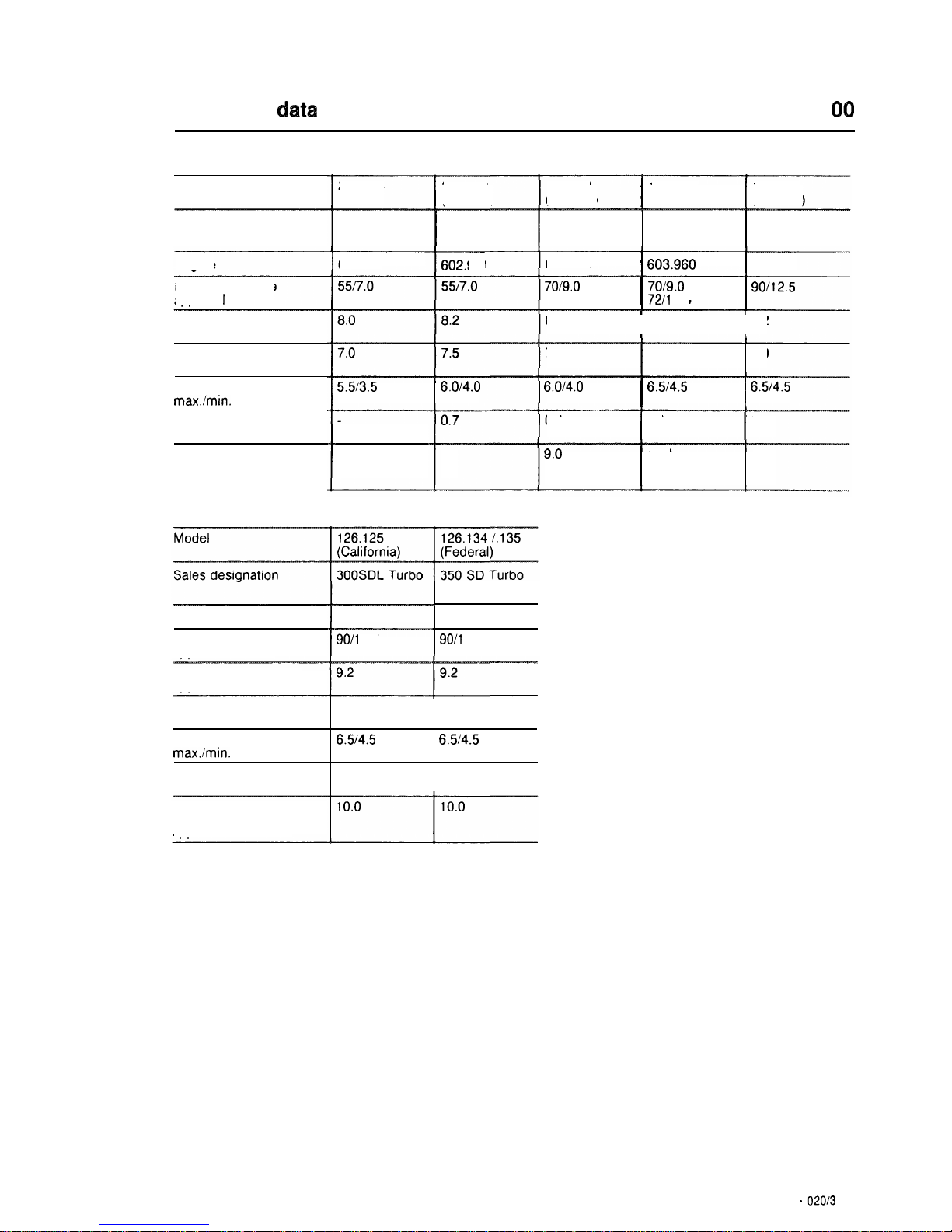
Technical
data
cm
Filling capacities
Model
201.126
I
201.128
(Federal)
124.128
(Federal)
I
124.133,
I
126.125
124.193
(Federal)
Sales designation
190 D 2.5 190 D 2.5
Turbo
300 D 2.5
Turbo
300 D Turbo 300 SDL Turbo
300 TD Turbo
Engine
602.911
-r-m
~
602.961
602.962
I
603.960
I ~~~
603.961
Fuel tank/reserve
aoorox.
I
7019.0
I
7019.0
I
90112.5
72/l
0.0
8.2
I
9.2
I
9.2
Engine oil initial filling
approx. I
During oil and filter
change approx. I
Marks on dipstick
max./min. approx. I
Oil-to-air cooler with
hoses
Cooling system with
heater
approx. I
7.0
I
8.0
I
8.0
6.Oi4.0
I
6.5i4.5
I
6.514.5
5.513.5
6.0/4.0
0.7
I
1.1
I
0.65
8.08.0
9.0
10.0 12.5
Filling capacities (continued)
~ 350 SDL Turbo
603.970
90/l
2.5
603.961
Engine
Fuel tan k/reserve
approx. I
90/l
2.5
Engine oil initial filling
approx. I
During oil and filter
change approx. I
Marks on dipstick
max./min. approx. I
Oil-to-air cooler with
hoses
8.0 7.5
6.514.5
6.514.5
0.65 0.65
Cooling system with
heater
aoorox. I
00 -
02013
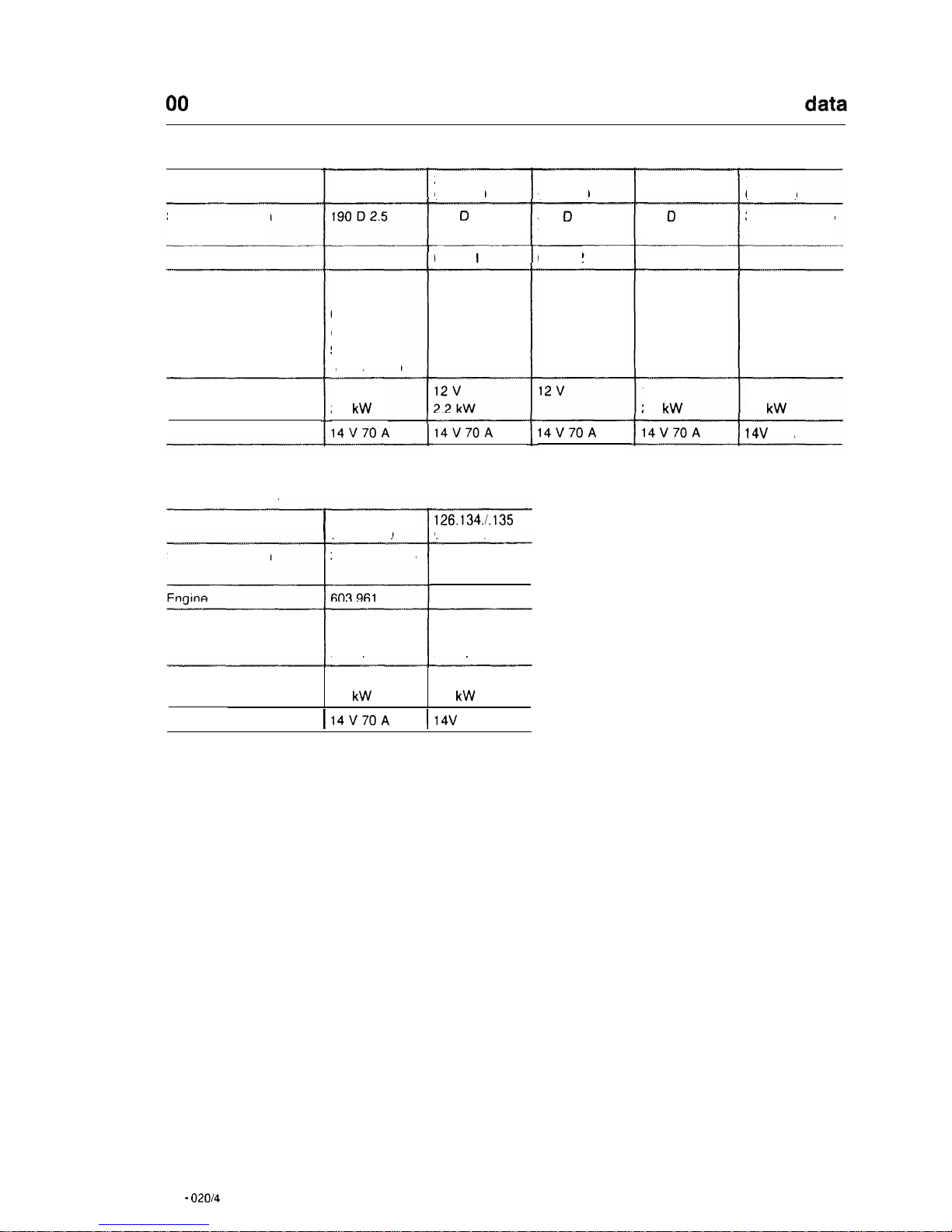
00
Technical
data
Electrical system
Model
201.128
(Federal)
124.128
(Federal)
124.133,
124.193
126.125
(Federal)
201.126
190 0 2.5
Turbo
300 D 2.5
Turbo
300 0 Turbo
300 TD Turbo
Sales designation
300
SDL Turbo
602.962
Engine
602.911
602.961
603.960
603.961
Battery
Voltage
Capacity
12v
62 Ah
(M.Y. 1986)
92 Ah (from
M. Y.
1987)
12 v
92 Ah
12v 12v
92 Ah
12v
92 Ah
12V
2.2
kW
12v
1.5
kW
Starter Bosch 12 v
2.2
kW
14V70A 14V70A
14v 80A
14V70A 14V70A
Alternator
Electrical system
Model
I
126.125
(California)
126.134.1.135
(Federal)
Sales designation 300SDL Turbo 350 SD Turbo
350 SDL Turbo
603.970
Battery
Voltage
Capacity
12v
62 Ah
12v
62 Ah
Starter Bosch
12 v 12v
2.2
kW
1.7
kW
Alternator
I
14V70A
I
14v 80A
00 -
020/4

Crankcase and Cylinder Head 01
01
Crankcase and cylinder
head
Job No.
Engine and model survey
................................................
01 - 001
Removal and installation of noise capsule at bottom of engine compartment
............
01 -
006
Opening hood, setting vertical warnings
...................................... 01 - 008
Testing compression pressure
.............................................
-
010
Checking cylinders for leaks
...............................................
-
015
Evaluating cylinder bores
.................................................
-
020
Removal and installation of engine (oil capacity)
.................................
-
030
Crankcase ventilation - Function
............................................
-
040
Measuring, boring and honing cylinder bores
...................................
-
110
Boring, honing and replacement of cylinder sleeves
..............................
-
115
Planing crankcase parting surface
...........................................
-
120
Removal and Installation of steel balls in main oil duct
............................
-
130
Replacement of freeze plugs in crankcase
.....................................
-
140
Removal and installation of timing cover
......................................
-210
Removal and installation of end cover
........................................
-
222
Removal and installation of oil pan
..........................................
-
310
Repair notes for cylinder heads and cylinder head gaskets
.........................
-
400
Refinishing prechamber sealing surface
.......................................
-
410
Removal and installation of cylinder head
.....................................
-
415
Removal and installation of prechambers
......................................
-
417
Facing cylinder head mating surface
.........................................
-
418
Boring out camshaft bearing bores (repair stage)
................................
-
419
Pressure-testing cylinder head
.............................................
-
420
01/l
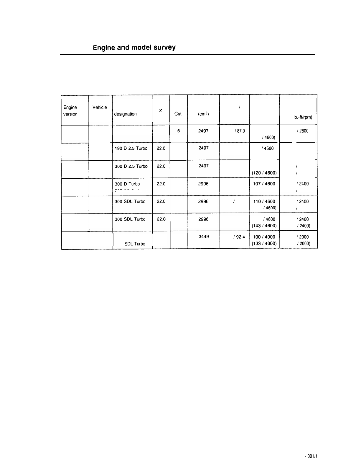
01-001
Engine
and
r?lodel
suwey
output
(SAE)
Kw(hp)/rpm
Torque (SAE)
Nm/rpm
(net
lb.-fthpm)
No.
Cyl.
Displacement
(cm?
Bore
I
Stroke
Engine
version
Vehrcle
model
Sales
&
desrgnation
190 D 2.5
I
22.0
84.0
187.0
201.126
165
12800
(12212800)
22812400
(16812400)
223 / 2400
(164 / 2400)
265
12400
(195 / 2400)
6914600
(93
14600)
92
14600
(12314600)
90 14600
(120/4600)
2497
602.911
84.0 187.0
602.961
Federal
5
201.128
84.0 187.0
602.962
Federal
5
124.128
2996
84.0 187.0
107/4600
(14314600)
603.960
124.133
124.193
6
300 TD
Turbo
87.0 / 84.0
110/4600
(148
/4600)
273
/2400
(201 / 2400)
603.961
Federal
126.125
6
2996
87.0 184.0
107
/4600
(143/4600)
265
12400
(195
12400)
603.961
126.125
6
2996
California
603.970
Federal
310
12000
(228
12000)
6
89.0
192.4
100/4000
(133/4000)
350 SD Turbo
22.0
350 SDLTurbo
126.134
126.135
1.10 -
001/l
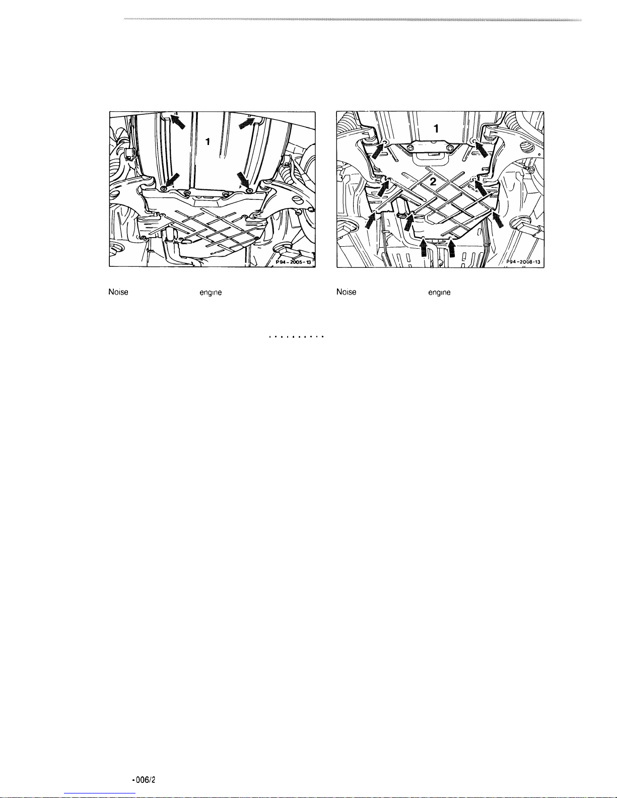
Model
201
Noise
capsule at bottom of
engine
compartment, front (1)
Noise
capsule at bottom of
engine
compartment, rear (2)
Noise capsule, front and rear (1, 2)
. . . . . . . . . .
Remove sheet metal screws (arrows), reinstall
and remove capsule, install.
Note
Install engine compartment capsule so that
edges of side part of capsule engage in bottom
part of capsule.
01.10 - 006/2
01-008
Opening
hood,
setting vertical,
warnings
AWarning
There is risk of injury whenever the engine is
running and the hood is open.
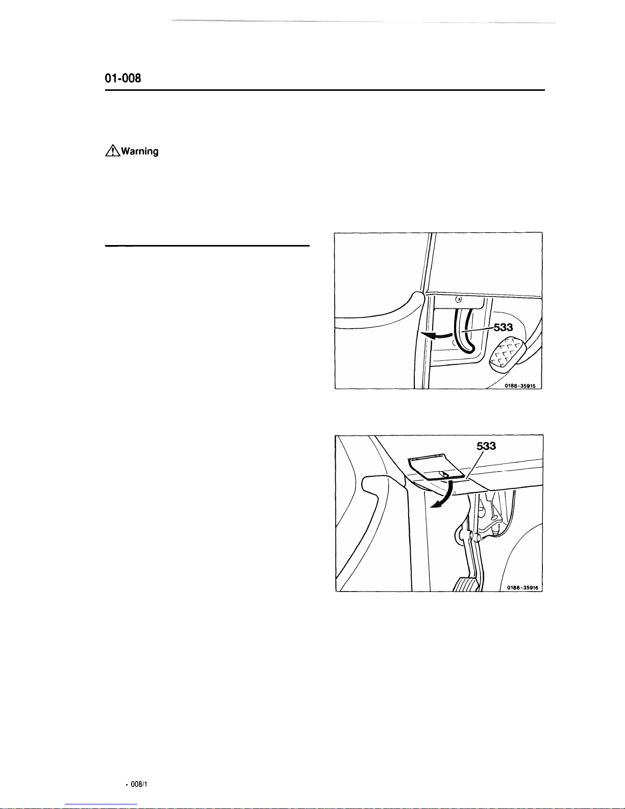
Opening hood
1
To unlock the hood, pull the lever (533) on
the left below the instrument panel in the
direction of the arrow. The hood opens to the
safety hook stop.
Model126
Model 124
01.10 -
008/l

2
Close hood by pushing down forcibly.
Model201
Model 124, 126, 201
3
Pull the handle (535) extending from the
grille as far as the stop and open hood (it may
be necessary to lift the hood slightly to release
the handle).
Note
Do
not attempt to lift the hood with handle (535).
The windshield wiper arm must not be pivoted
forward when the hood is lifted.
Moving hood into vertical position
Model 124 (production up to August 1988)
4
Push lock lever (537) on the left hood
support (536) in direction of arrow. Lift hood
slightly upward to keep the lock lever (537) from
reengaging again.
Repeat the preceding at the right hood support
and set the hood in a vertical position.
5
To close the hood, push in lock lever at the
right hood support, and close the hood by
pushing down forcibly.
1.10 -
00812
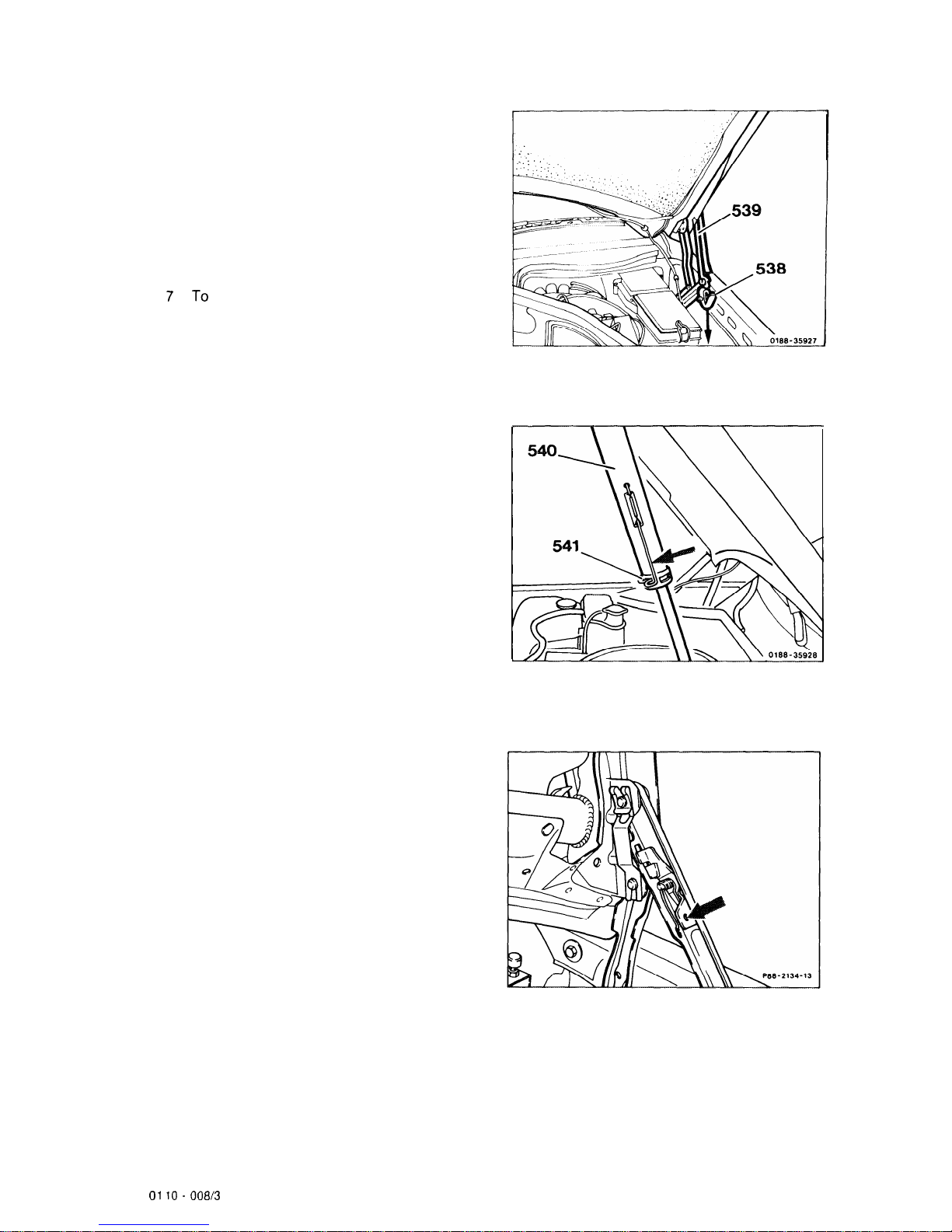
Model 126
6
Push hood down slightly. Push lock lever
(538) on the left hood support (539) down in the
direction of the arrow. Push hood up slightly to
keep the lock lever (538) from reengaging.
Repeat the preceding at the right hood support
and set the hood in a vertical position.
7
To
close the hood, push the lock lever (538)
at the left hood support in the direction of the
arrow, and close the hood by pushing down
forcibly.
Model 201
8
Pull lock (541) on hood damper (540) in
direction of arrow and set the hood in a vertical
position.
9
When the hood is set vertical, a lock
engages on the left hood support.
10 Close hood. Push in the lock lever (arrow)
and close the hood by pushing down forcibly.
01 10 -
008/3

01-010
Testing compression pressure
Engine
,..............................
warm up to operating temperature
(approx. 80
“C)
(item
1).
Note
Check compression only with engine at
operating temperature.
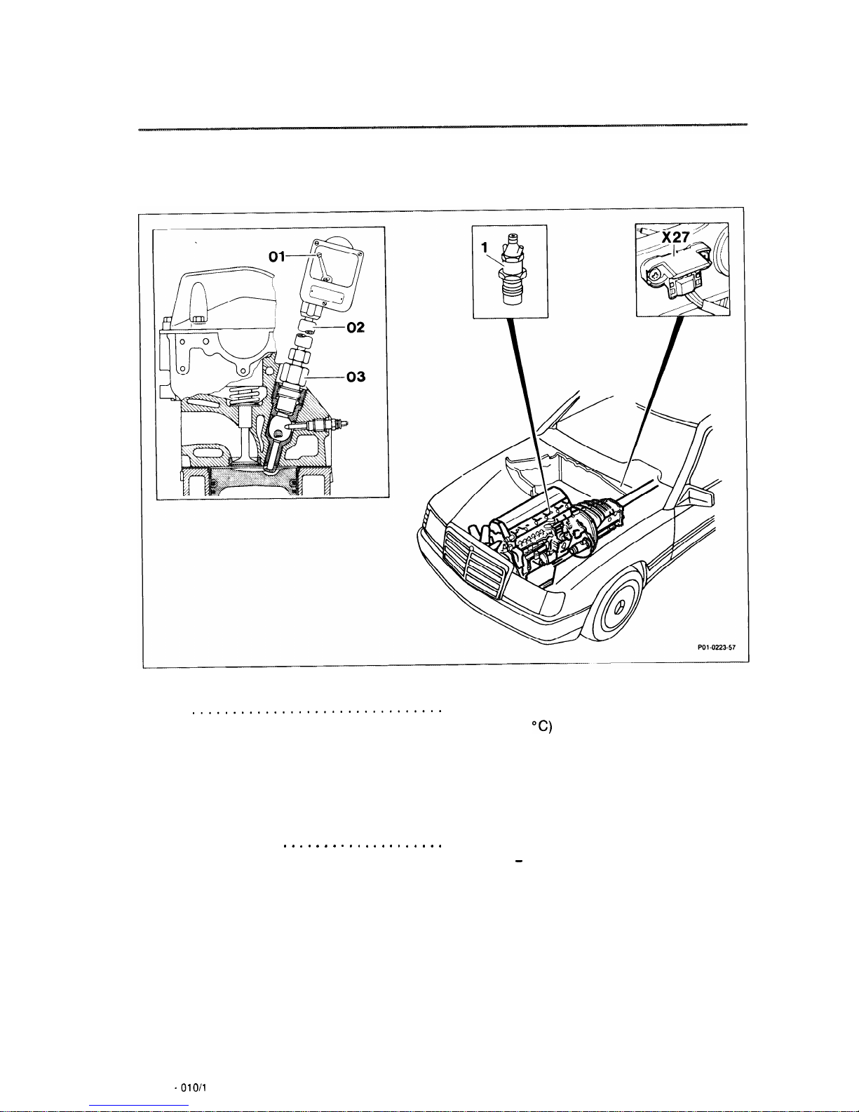
Nozzle holder (1)
. . . . . . . . . . . . . . . . . . . . . . .
remove, install (07-230).
Plug connector (X27)
. . . . . . . . . . . . . . . . . . . .
for starter harness, disconnect, reconnect
(items 3 - 4).
Note
The plug connector (X27) illustrated in the figure
is installed on model 124. The installation point
and version of the plug connector differs
depending on the model.
01.10 -
010/l
Contact handle . . . . . . . . . . . . . . . . . . . . . . . .
.
for compression pressure recorder
001 589 78 21 00, connect, adapter line
124 589 36 63 00 (items 3 - 5).
Engine . . . . . . . . . . . . . . . . . . . . . . . . . . . . . . .
turn over a number of times to clean out; the
transmission must be in neutral and the shutoff
lever on the injection pump pressed to “stop”
(item 6).
Compression pressure recorder (01)
. . . . . . . . .
bolt appropriate adapter (03) and flexible
connector (02) into precombustion chamber of
cylinder to be checked (item
7).
Compression. . . . . . . . . . . . . . . . . . . . . . . . .
.
check; shift transmission to neutral and turn
engine over at least 9 revolutions with the
shutoff lever on the injection pump pushed to
“stop” (items 8 - 9).
Note
Check compression in remaining cylinders in
same manner.
Measured compression values . . . . . . . . . . . . . .compare with specified test values (item 10).
Note
If
one or more cylinders do not have the
minimum compression, determine cause.
Test values with engine at operating temperature (approx. 80
“C)
bar
Compression pressure, normal
26 - 32
Minimum compression pressure approx. 18
Permissible difference between individual cylinders
max. 3
Tightening torques
Nm
Union nuts on injection lines (reference value) 10-20
Nozzle holders in prechambers
70+10
Nozzle holders for angular injection
30
01.10 -
01012
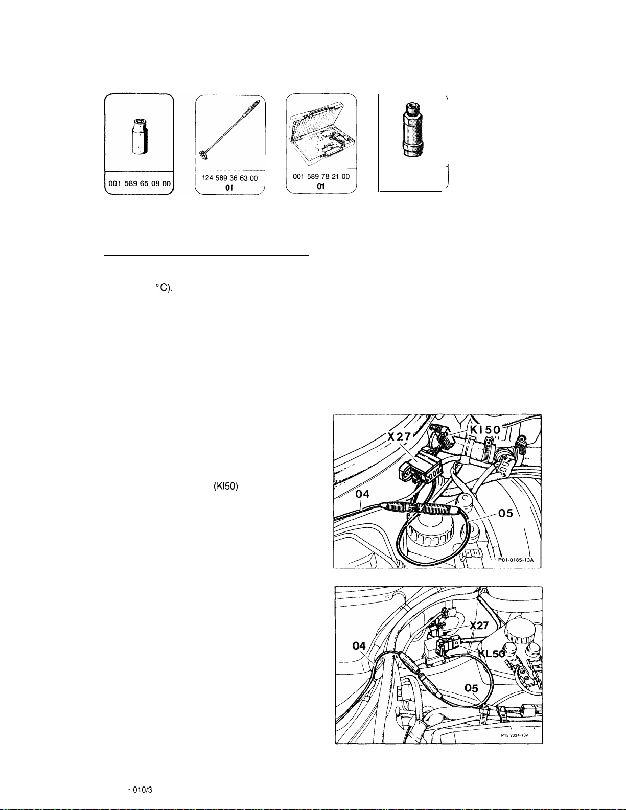
Special tools
Testing
1
Warm engine up to operating temperature
(approx.
80
“C).
Note
Check compression only with engine at
operating temperature.
2
Remove all nozzle holders
(07-230).
Models 124 and 126
3
Connect contact handle for compression
pressure recorder 001 589
78
21 00; disconnect
plug connector
(X27)
on left side of engine
compartment and connect connection line
(04)
of contact handle to plug
(Kl50)
with adapter line
(124 589 36 63 00 (05).
602 589 00 6300
ol
!
Model124
Model126
01.10 -
010/3
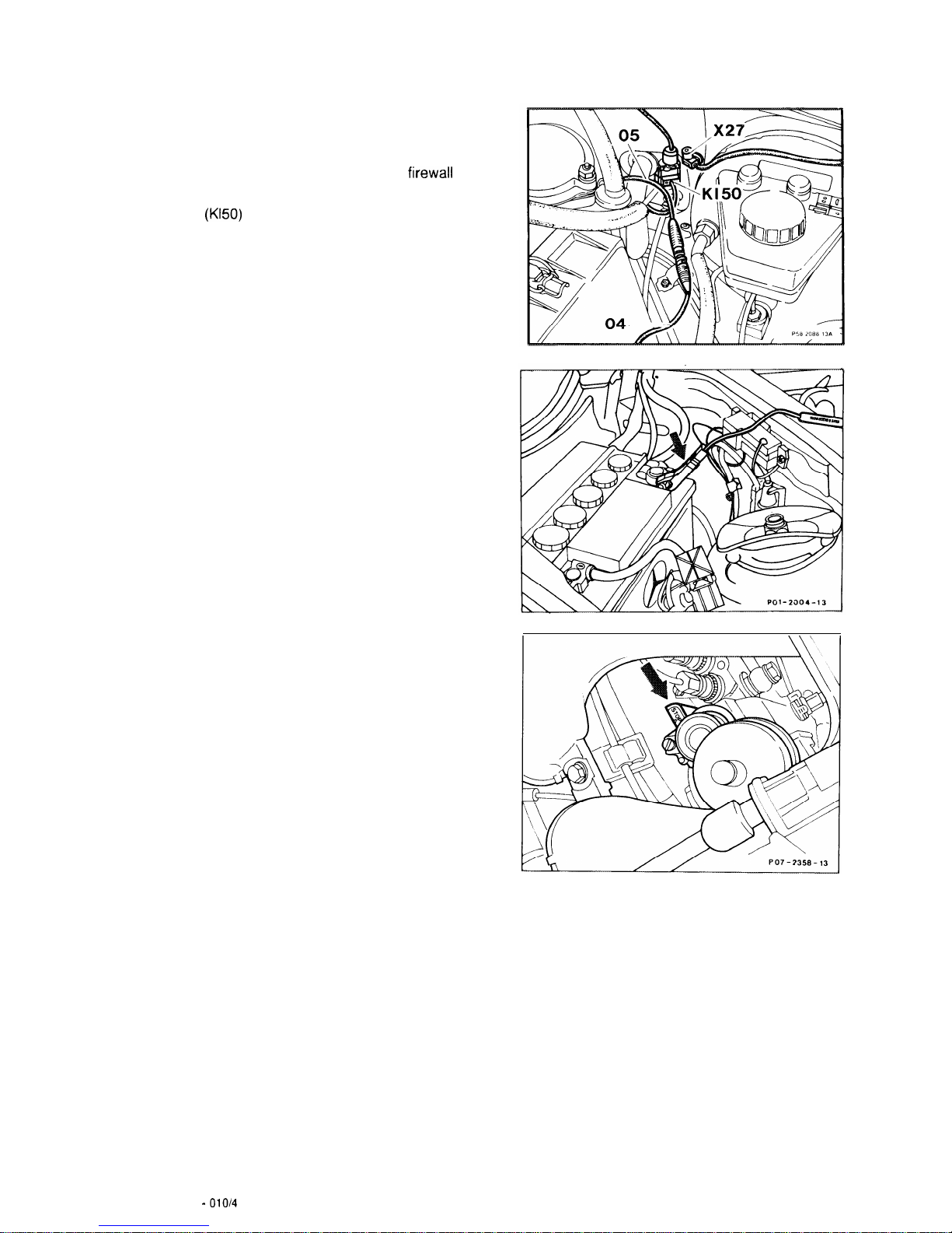
Model 201
4
Connect contact handle of compression
pressure recorder 001 589
78 21 00;
disconnect
plug connector (X27) on left side of
firewall
and
connect connection line (04) of contact handle to
plug
(Kl50)
with adapter line 124 589 36 63 00.
5
Connect second connection line from
contact handle to positive pole (K130) on battery
(arrow).
6
Crank engine a number of times with starter
with transmission in neutral and shutoff lever on
injection pump (arrow) pressed to “stop” to
remove combustion residues in the
precombustion chamber of the cylinder.
Note
Always hold shutoff lever on injection pump
depressed when cranking engine. This prevents
fuel from being pumped and therefore running
out of the disconnected injection lines.
01.10 -
01014
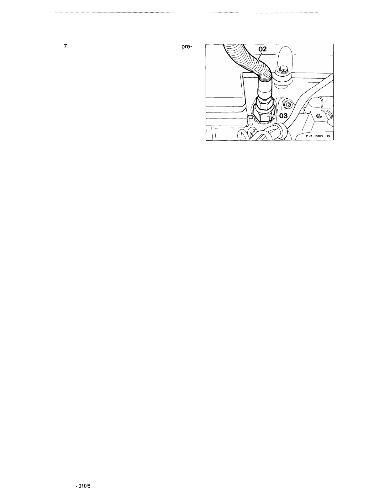
7
Bolt compression pressure recorder into
pre-
chamber of cylinder to be tested with appropriate
adapter (03) and flexible connector (02).
Note
On engines with angular injection use adapter
602 589 00 63 00.
8
Crank engine at least 8 revolutions to test
compression.
9
Perform test on remaining cylinders in same
manner.
10 After completing the compression test
compare pressures measured with specified
values.
Note
If one or more cylinders do not have the
minimum compression pressure, check cylinder
for leakage (01-015) and determine cause.
11 Install in reverse order.
01.10 -
OlO&
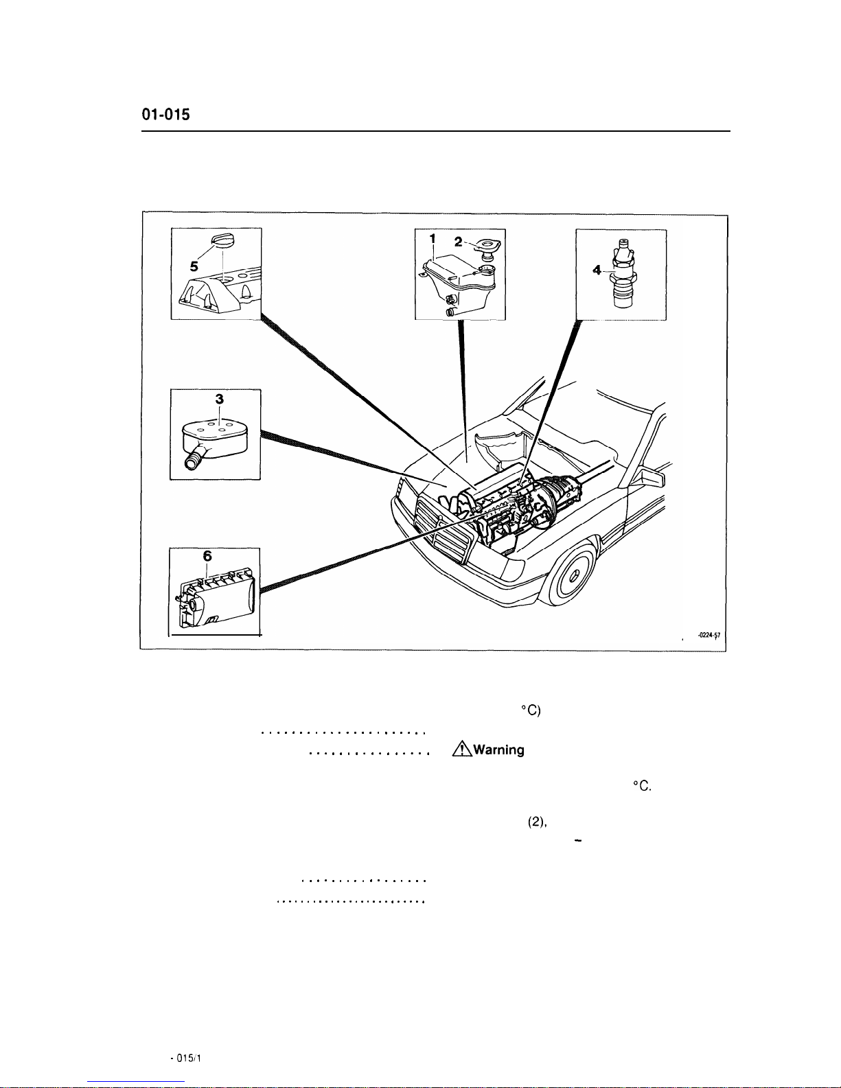
01-015
Checking cylinders for leaks
PO1 4224-57
Engine . . . . . . . . . . . . . . . . . . . . . . . . . . . . . . .
warm up to operating temperature
(approx. 80 “C) (item 1).
Nozzle holders (4)
. . . . . . . . . . . . . . . . . . . . . .
remove, install
(07-230).
Coolant expansion tank (1)
. . . . . . . . . . . . . . . .
AWarning
Open cap (2) on coolant expansion tank only at
coolant temperatures below 90 “C.
Remove cap
(2)
install. Add coolant,
if necessary (items 3 - 4).
Air cleaner on naturally aspirated engines (6)
and on Turbo-engines (3)
. . . . . . . . . . . . . . . . .
remove air cleaner cover, install (item 5).
Oil filler cap (5) . . . . . . . . . . . . . . . . . . . . . . . .
.
remove, install (item 6).
01.10 -
015/l
Engine . . . . . . . . . . . . . . . . . . . . . . . . . . . . . . .
move piston of cylinder to be checked to TDC,
ignition stroke, connect and calibrate cylinder
leakage tester (items 7 - 9).
Cylinder
. . . . . . . . . . . . . . . . . . . . . . . . . . . . . .
determine pressure loss (items 10 - 12).
Note
Check other cylinders in firing order.
Permissible pressure loss
Total, engine
max. 25
%
Valves and cylinder head gasket
max. 10 %
Piston rings
max.
20
%
Tightening torques
Union nuts on injection lines (reference value)
Nm
10-20
Nozzle holders in prechambers
70+10
Nozzle holders for angular injection
30
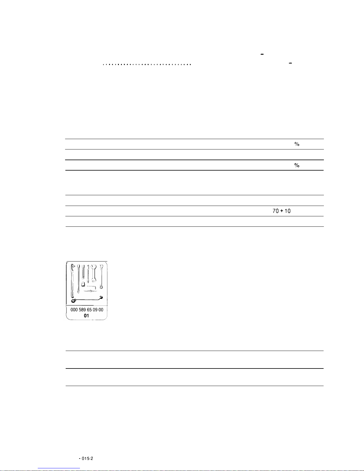
Special tool
1 000589650900
Commercially available tools
Cylinder leakage tester
e.g.
Bosch, EFAW 210 A
Sun, CLT 228
Adapters and connectors
e.g. Bosch
Order no. 1 687 010 016
01.10 -
01512

Testing
1
Warm engine up to operating temperature
(approx. 80 “C).
2
Remove all nozzle holders (07-230).
A
Warning
Open cap on coolant expansion tank only at
coolant temperatures below 90 “C.
3
Remove cap on coolant expansion tank.
4
Check coolant level in coolant expansion
tank and add, if necessary.
5
Open retaining strap on air cleaner cover on
naturally aspirated engines or unscrew hex. head
bolts on air cleaner cap on Turbo-engines,
remove air cleaner cap and take out filter
cartridge.
6
Remove
011
filler cap.
7
Move piston in cylinder to be checked to
TDC, ignition stroke.
8
Bolt appropriate adapter (01) with straight or
angular connector (02) into precombustion
chamber of cylinder to be checked.
9
Calibrate cylinder leakage tester and bolt
connection hose (03) of tester onto connector
(02).
01.10 -
01X.3
 Loading...