

Mercedes-Benz 201.024, 201.028 Service Manual
Mercedes-Benz
Mercedes-Benz of North America, Inc. - Montvale, NJ 07645

0 Mercedes-Benz of North America, Inc., 1993
All rights reserved. Reproduction by any means, electronic or mechanical, including photocopying, recording, or by any information storage and retrieval system
or translation in whole or part is not permitted without
written authorization from the publisher.
Published by Mercedes-Benz of North America, Inc.
Printed in U.S.A.
Part number S-2347-93A

Introduction
This service manual is the product of existing technical publications. Special care has been taken
to provide accurate information on removal, disassembly, inspection, installation, and adjustment
procedures, together with the necessary technical data for the particular job.
The material in this manual is divided according to the Mercedes-Benz Component Group System
as outlined on the GROUP INDEX page. This page will quickly direct the reader to the Major
Component Group. Each Major Component Group begins with a JOB INDEX listing all jobs within
that group.
Mercedes-Benz of North America, Inc. recommends that repairs to, and maintenance of
Mercedes-Benz automobiles be performed by
trained Mercedes-Benz personnel
at authorized
Mercedes-Benz dealerships.
The information contained in this special publication is ordinarily issued by Mercedes-Benz of
North America, Inc., in conjunction with supplementary service literature and special tools supplied
only to
its authorized dealers.
The repair and maintenance procedures outlined herein are
intended for use by
trained Mercedes-Benz service and dealership personnel. This
manual
can also be useful for Mercedes-Benz owners in diagnosing vehicle systems and performing
repairs. Supplementary service literature will not be provided with this publication, but may be
contained in reprints of this service manual.
Please note that this manual has been compiled from various sources, some of which cover
models other than the subject of this book.
Always refer to the engine and vehicle identification
table for model and component information.
Special tools required in performing certain service jobs are identified in the manual and are
recommended for use. Any part numbers given are only used for identification and easier
differentiation between individual components, and are not intended for ordering purposes.
If your Mercedes-Benz model differs from the specifications contained in the manual you select,
consult your authorized Mercedes-Benz dealer.
All procedures, illustrations and specifications contained in this manual were based on the latest
information available at the time of publication. All rights are reserved to make production, design
and specification changes at any time, without notice and without obligation to give notice. Any
such changes will not be contained in this manual.
Caution!
The proper performance of service and repair procedures is essential for both the safety of the
mechanic and the safe and efficient operation of the vehicle. The use of incorrect service
procedures and tools may greatly increase the risk of personal injury and render the vehicle
unsafe. The procedures in this manual are described in such a manner that the service may be
performed safely and accurately.
However, it is a general assumption that the reader is familiar with basic automotive
procedures and Mercedes-Benz vehicles. You should not attempt to use this manual if this
the case.
repair
is not
Mercedes-Benz of North America, Inc. assumes no liability for any damage to person or property
caused by the utilization of this publication to effect maintenance or repair work on Mercedes-Benz
automobiles.
MERCEDES-BENZ OF NORTH AMERICA, INC.
Service and Parts Literature

Group Index
General, Technical Data
00
Crankcase and cylinder head
01
Crankshaft assembly
03
Engine timing, valvetrain
05
Continuous Fuel Injection System (CFI) 07.3
Air filter
09
Belt drive
Intake and exhaust manifolds, emission control system
14
Electrical system, engine
15
Engine lubrication system
Engine cooling system
20
Engine suspension
22
Accelerator control, cruise control, electronic accelerator
30
Fuel system
Exhaust system

General,
technical
data
00

00
General,
technical
Job No.
Instructions for use of service manual
....................................... 00 - 005
Engine and vehicle identification
............................................
-
010
Vehicle identification number locations
.......................................
-
015
Technical data ........................................................
-
020
00/l
Instructions for use of
servic
00-005
Complete Service Manual coverage for late
model year Mercedes-Benz vehicles requires
four individual manuals:
Service Manual, Engine
Service Manual, Chassis and Body
Service Manual, Automatic Climate Control
Electrical Troubleshooting Manual
Throughout these manuals, the vehicles are
identified by their chassis and engine numbers.
These numbers are made up of the first six digits
of the respective serial number. For the actual
location of chassis and engine numbers, see
page
00-015’1.
In cases where the repair
instructions apply to all versions, only the first
three digits of the respective number are
referenced.
For example, chassis 124 applies to all
124
models. However, chassis
124.051
would apply
only to model 300CE with engine 104.
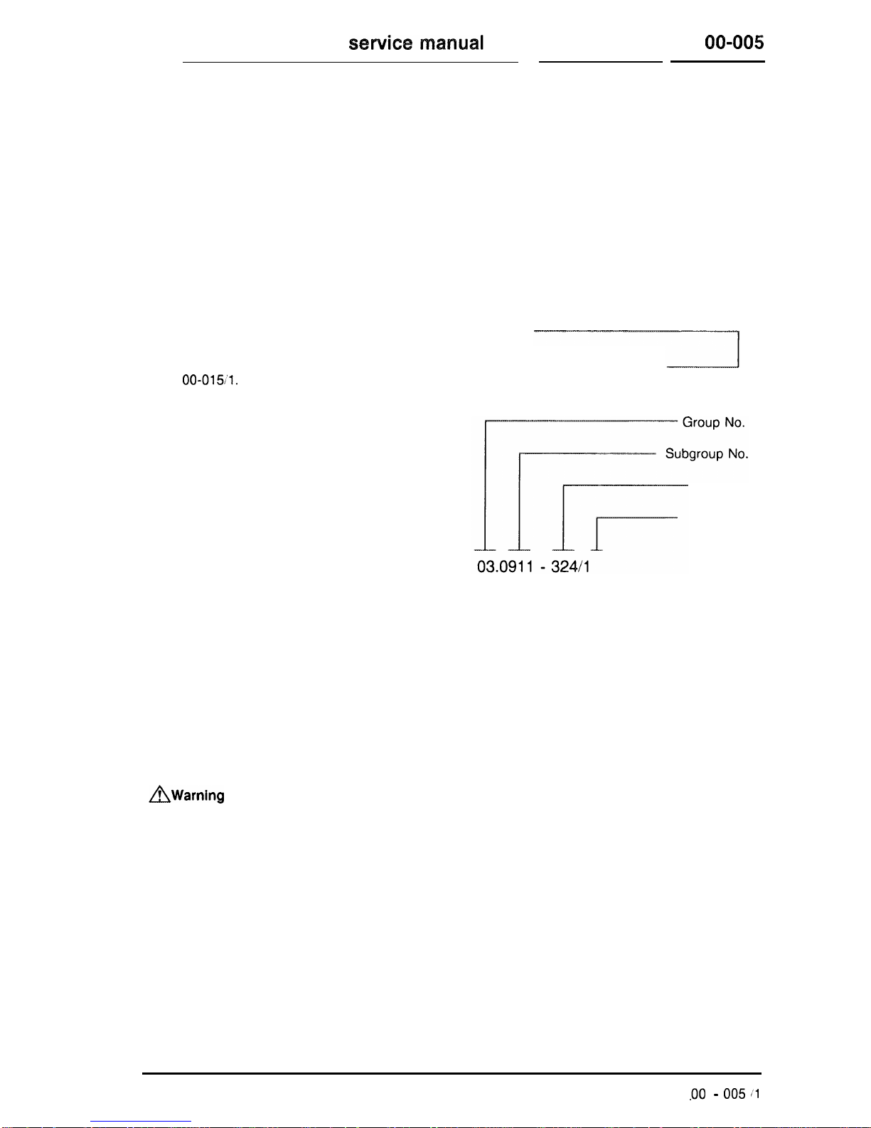
Location of specific repair instructions
First locate the Group No. in the Group Index.
Individual groups are separated by an easily
visible dividing page, which is followed by the job
index page. The exact job required is found in
the job index. The initial page of a typical job
description appears as follows:
03-324
Replacement of front crankshaft
radial seal
Job Title appears on
same line as Group
No.
Job No.
Page No.
Technical data, tightening torques and tools are
listed at the beginning of each job.
All dimensions are in metric units unless
otherwise indicated. Any part numbers given are
only used for identification and differentiation
between individual components, and are not
intended for ordering purposes.
Special Instructions
AWarning
Appears throughout service instructions indicating the possiblity of personal injury
if procedures are not followed.
Caution!
Indicates possible equipment or vehicle damage if procedures are not followed.
Note
Provides helpful information for the described procedure.
Installation note
Provides detailed information during assembly.
.oo -
005 11
ine
and vehicle identification
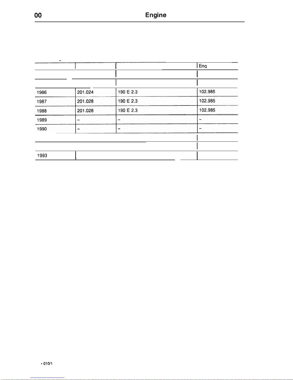
This manual applies to the following passenger cars, starting model year 1984.
Gasoline engines
Model Year
1
Model
1
Sales Designation
IE
9
n.
ine
1984
I
201.024
I
190
E 2.3
I
102.961
1985
I
201.024
I
190
E 2.3
I
102.985
1991
I
201.028
I
190
E 2.3
I
102.985
1992
I
201.028
I
190
E 2.3
I
102.985
1993
I
201.028
I
190
E 2.3
I
102.985
00 -
010/l
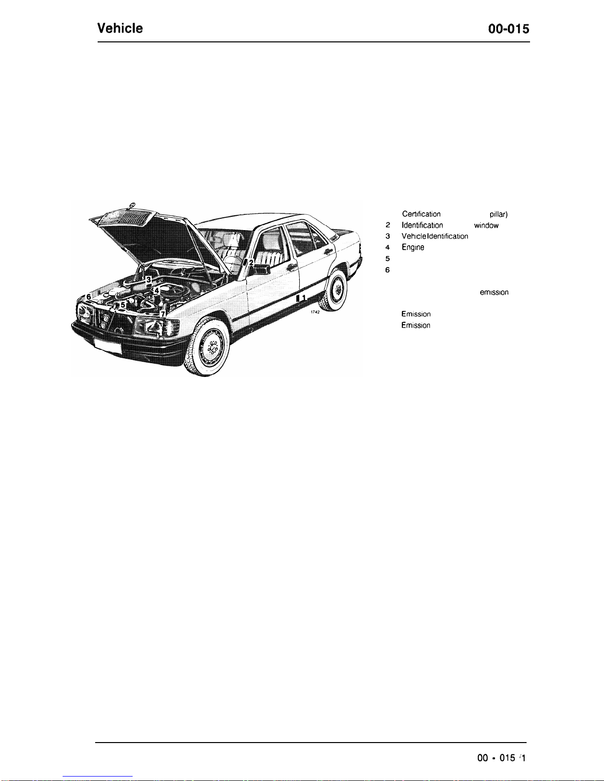
Identification number locations
00-615
Model
201
When ordering spare parts, please specify
chassis and engine numbers.
7
a
Certrfication
Tag (left door
plllar)
ldentlficatlon Tag (left wlndow post)
Vehicle ldentlficatlon No.
Engine
No.
Body No. and Paintwork No.
lnformatron Tag
California version
Vacuum line routing for
emission
control system
Emlsslon
Control Tag
Emlsslon
Control Tag
Catalyst Information
(from model year 1964 up to 1966)
00 - 015 I1
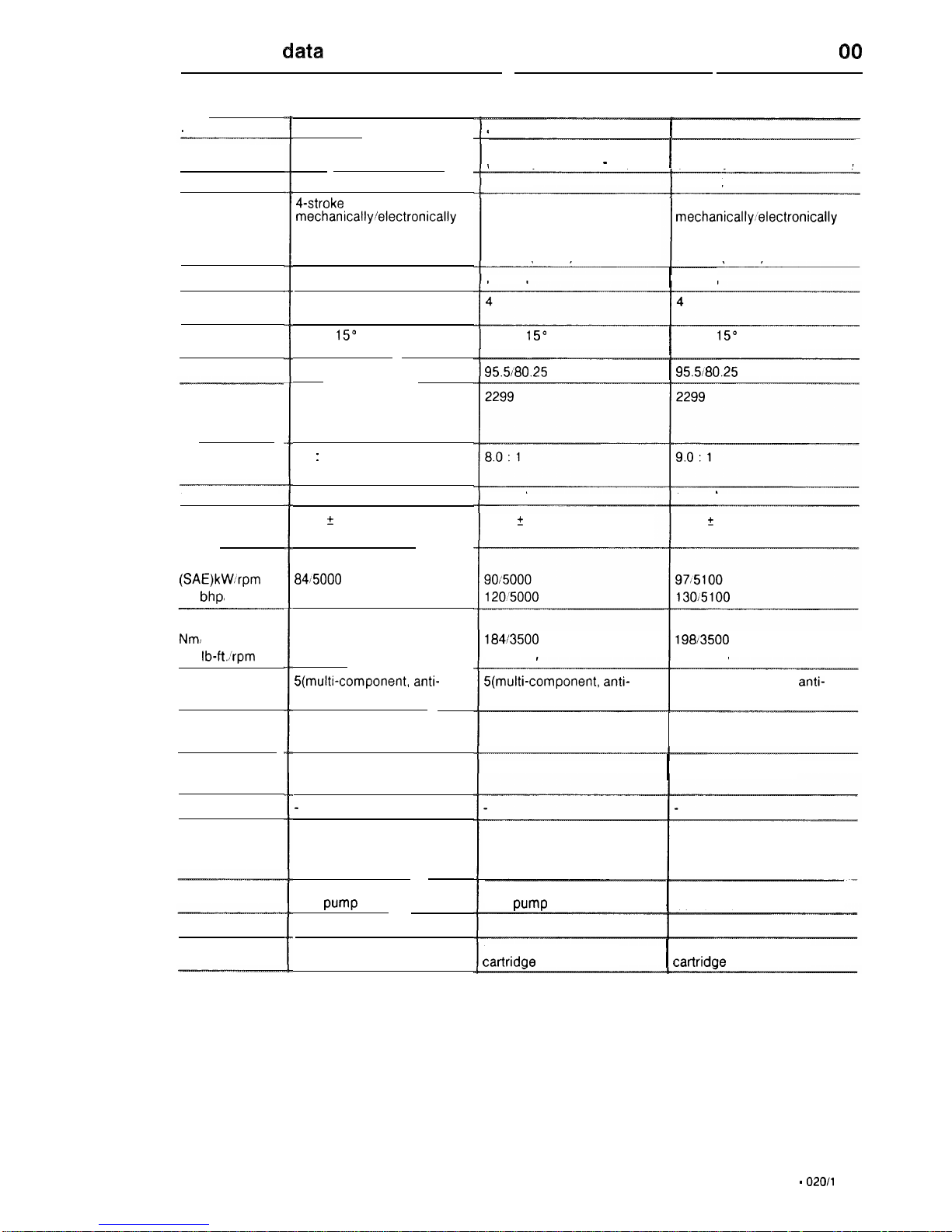
Technical
data
00
Gasoline engines
201.024
1
201.028
Model
20
1.024
190 E 2.3
(Model year 1984)
102.961
4-stroke spark ignition,
mechanicallyielectronically
controlled continuous fuel
injection system with airflow
sensor (CIS-E)
Normal
4
In-line
15”
inclination
95580.25
2299
8.0 : 1
l-3-4-2
5700 t 50
8415000
11315000
18113500
13313500
S(multi-component,
anti-
friction bearings)
Overhead, 2 per cylinder
1 overhead camshaft
Coolant circulation pump,
thermostat with bypass line,
fan with electromagnetic
clutch, finned tube radiator
Pressure lubrication via gear
type
pump
Full flow filter
Dry air filter with paper
cartridge
190 E 2.3 190 E 2.3
(Model years
1985-86)
I
(Model years
1987-8, 1991-3)
Sales
designation
Engine
Operation
102.985
102.985
4-stroke spark ignition,
mechanically/electronically
controlled continuous fuel
injection system with airflow
sensor (CIS-E)
4-stroke spark ignition,
mechanically~‘electronically
controlled continuous fuel
injection system with airflow
sensor (CIS-E)
Normal
I
Normal
Aspiration
Number of
cylinders
Cylinder
arrangement
Bore, stroke mm
In-line
15”
inclination
I
In-line 15” inclination
95.5180.25
I
95.5/80.25
Total effective
piston
displacement cc
Compression
ratio
l-3-4-2 l-3-4-2
Firing order
Maximum speed
rpm
Engine output
(SAE)kWrpm
net
bhp,
rpm
6200 A 50
6200 2 50
Maximum torque
Nm,
rpm
net
lb-fti’rpm
Crankshaft
bearings
Valve
arrangement
Camshaft
arrangement
Oil cooling
Cooling
184/3500
1361’3500
198/3500
14613500
S(multi-component, anti-
friction bearings)
5 (multi-component, anti-
friction bearings)
Overhead, 2 per cylinder
Overhead, 2 per cylinder
1 overhead camshaft
I
1 overhead camshaft
Coolant circulation pump,
thermostat with bypass line,
fan with electromagnetic
clutch, finned tube radiator
Coolant circulation pump,
thermostat with bypass line,
fan with electromagnetic
clutch, finned tube radiator
Lubrication
Pressure lubrication via gear
I
Pressure lubrication via gear
type
pump
type pump
Full flow filter
Full flow filter
Oil filter
Air filter
Dry air filter with paper
cartridqe
I
Dry air filter with paper
cartridae
00 -
020/l

.i._. . . . . . .
.
QQ
Technical
data
Filling capacities
Model
1
201.024
1
201.024
1
201.028
Sales
designation
190 E 2.3 190 E 2.3 190 E 2.3
(Model Year
1984)
(Model Years
1985-6)
(Model Years
1987-8,
1991-3)
I
I
I
Engine
1
102.961
I
102.985
1
102.985
Fuel tank/reserve approx. I
Electrical system
Starter Bosch
00 - 02012

Crankcase and cylinder head
01

01
Crankcase and cylinder head
Job No.
Engine and model survey
................................................
01 - 001
Overview - Engines
....................................................
01 - 005
Removal and installation of bottom engine compartment cover
.....................
01 - 006
Testing compression pressure
..............................................
-
010
Testing cylinder leaktightness
...............................................
-
015
Illuminating cylinders
.....................................................
-
020
Removal and installation of engine
...........................................
-
030
Crankcase ventilation - function
.............................................
-
040
Measuring, boring and honing cylinders
........................................
-
110
Facing crankcase parting surface
............................................
-
120
Removal and installation of steel balls in main oil gallery
............................
-
130
Replacing core plug in crankcase
...........................................
-
140
Removal and installation of timing case cover
...................................
-
210
Removal and installation of end cover
.........................................
-
222
Removal and installation of oil pan
...........................................
-
310
Repair instructions for crankcase,
.............................................
-
403
Removal and installation of cylinder head cover
..................................
-
406
Reconditioning spark plug thread in cylinder head
................................
-
407
Removal and installation of cylinder head
......................................
-
415
Matching measuring sensors to cylinder head
...................................
-
416
Facing cylinder head mating face
............................................
-
418
Enlarging camshaft bearing bores (repair size)
...................................
-
419
Pressure-testing cylinder head
..............................................
-
420
01.11
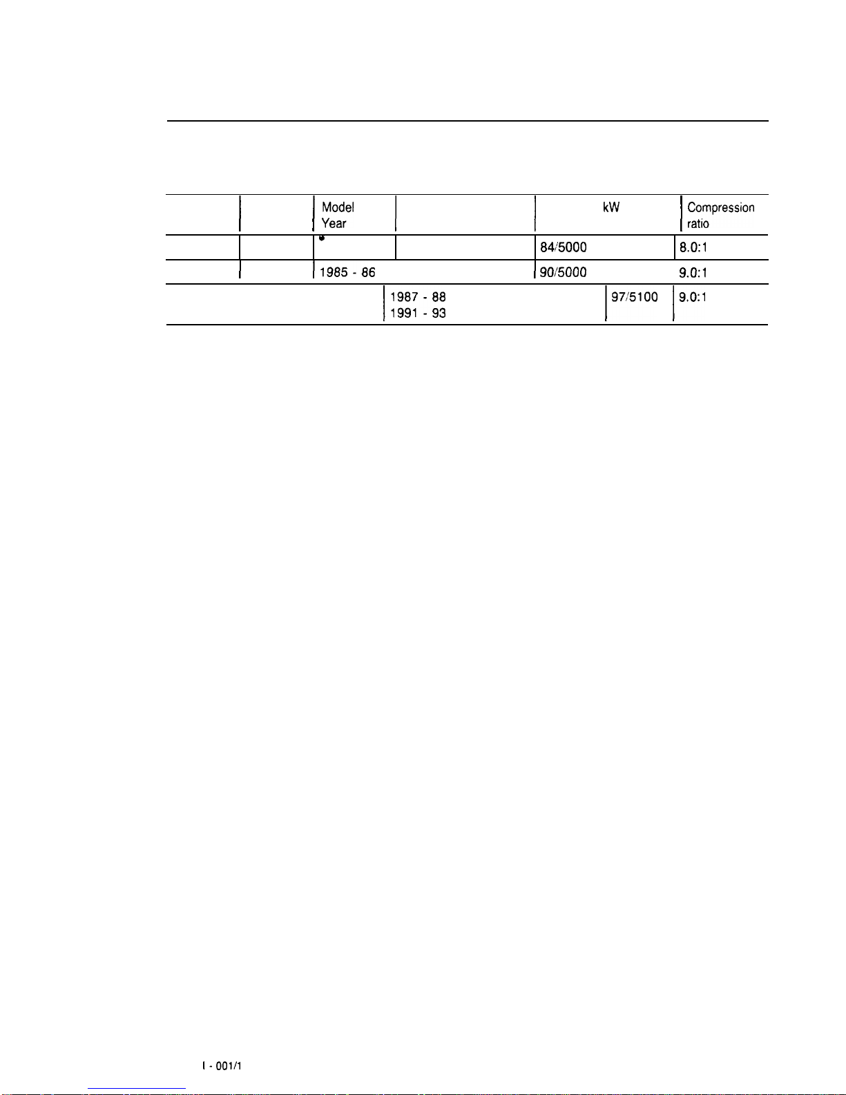
01-001
Engine and Model Survey
Engine1 Model1
y;m;l
1
Sales designation) Power in kW at rprn /
z;pression
*
102.961
201.024
1984
190 E
2.3
84:5000
8.O:l
102.985
I
201.024
11985-86
1190E2.3
I
90/5000
I
9.0:1
102.985
1201.028
1;;;;;;;
ll9OE2.3
197:5100 19.0:1
01.1101 l-001/1
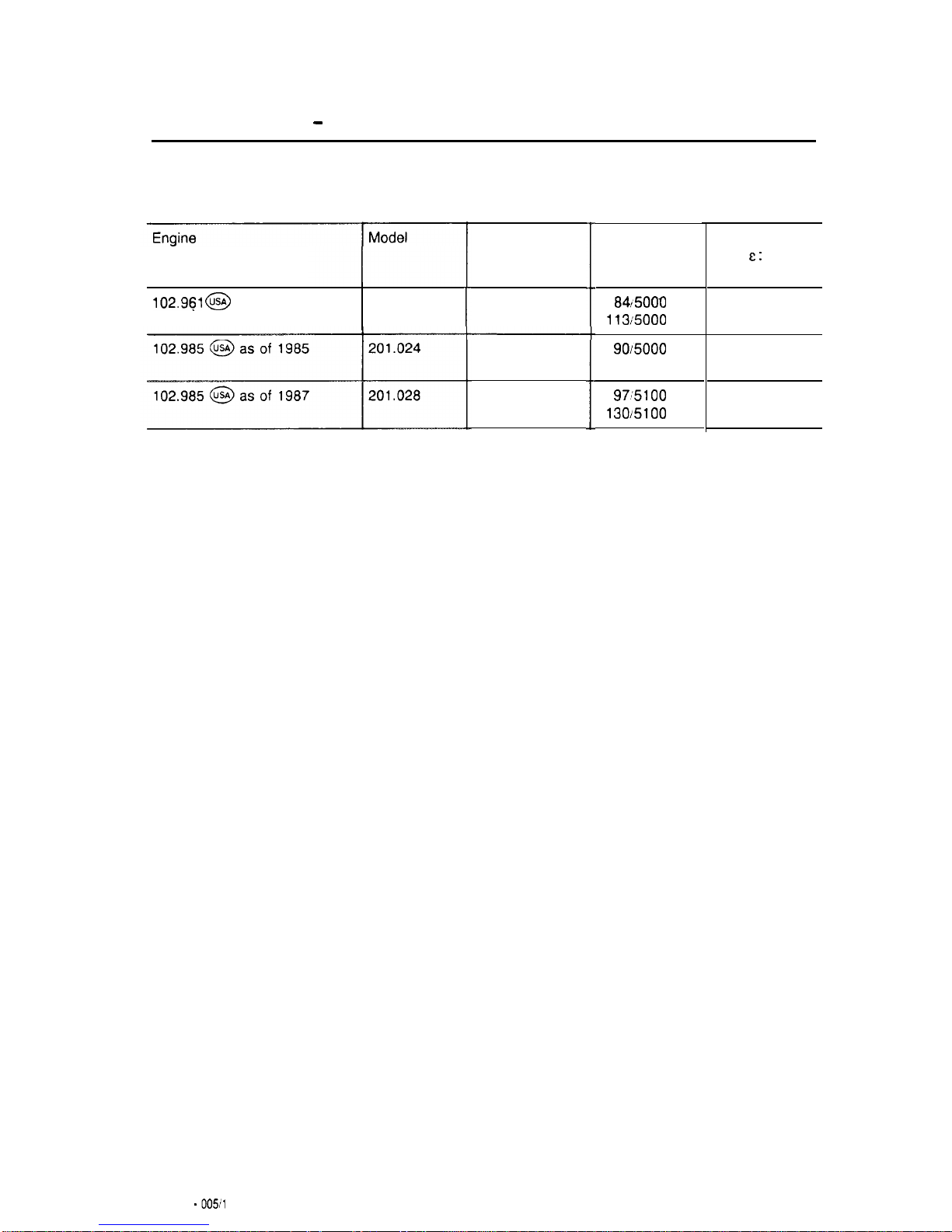
01-005
Overview - Engines, Models, Output and Compression Ratio
102.961 @
as of 1984
201.024
Sales
designation
190 E 2.3
190 E 2.3
190 E 2.3
Output in KW
at rpm
net bhpirpm
84/5000
113i5000
90/5000
12015000
97:5100
130/5100
Compression
ratio E : 1
8.0
8.0
9.0
01.0904
-
005il
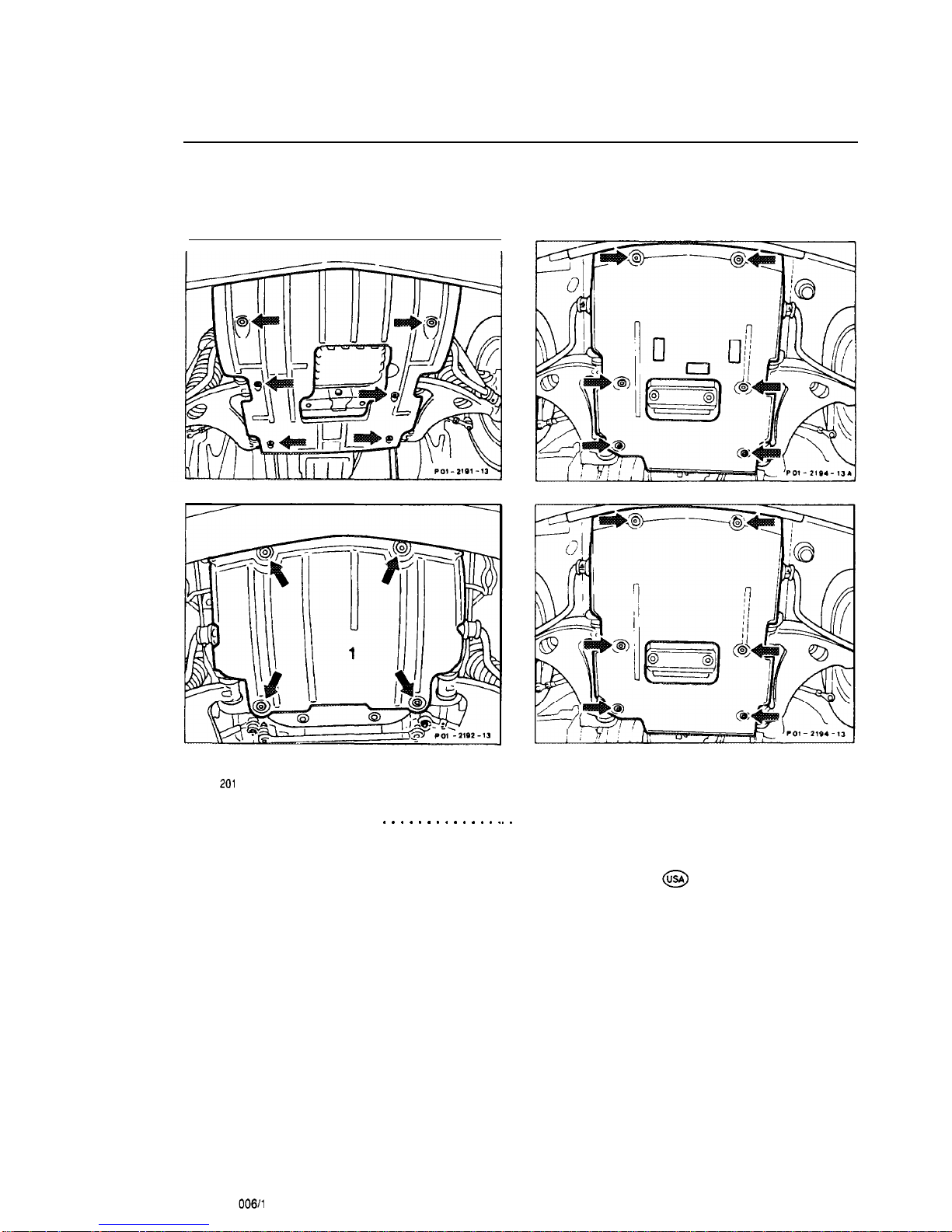
01-006
Removal and installation of bottom engine compartment cover
Model
201
Self-tapping screws (arrows)
. . . . . . . . . . . . . ,
, .
remove, screw in and remove, install engine
compartment cover.
Note
On Model 201.028 @ install engine
compartment cover so that the edge of the side
parts grips above the bottom part.
01.0904 .
006/l
,_L,x,~~.~...z.Y
.
.
________ii__________...........
..,
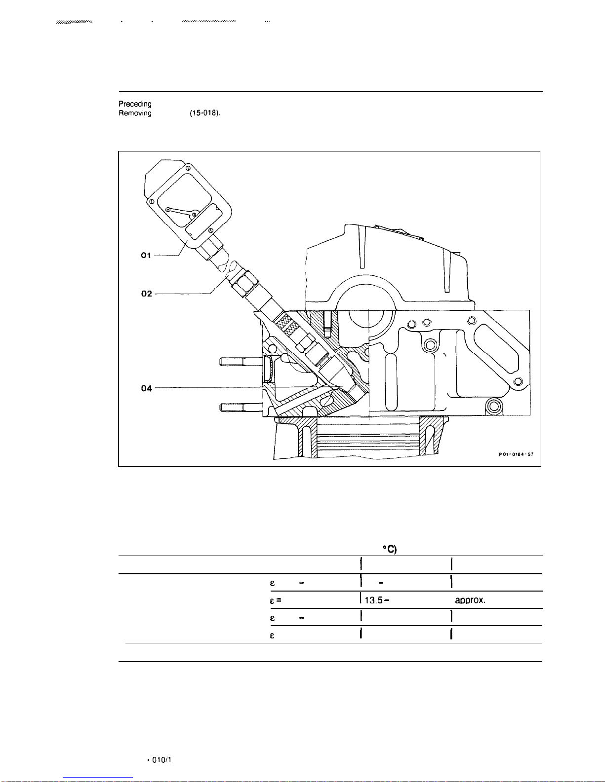
01-010
Testing compression pressure
Precedmg
work:
Rernovtng
spark plug
(15-016).
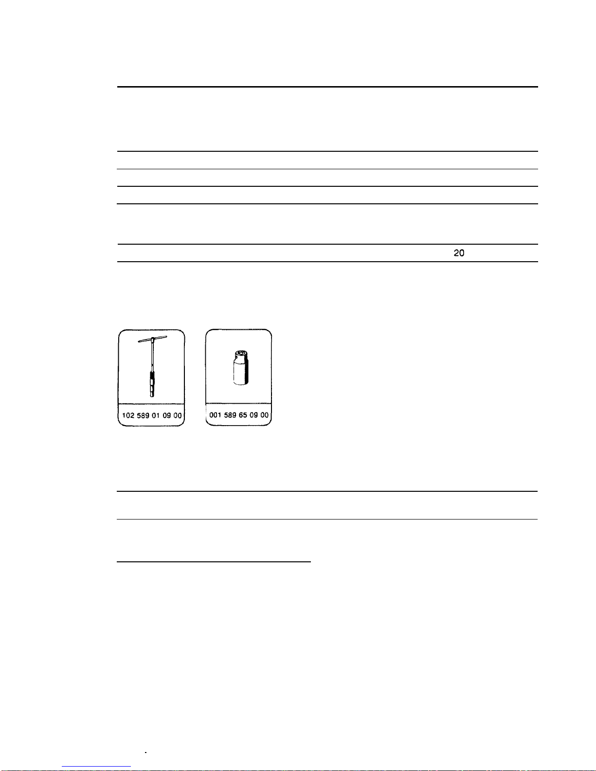
01
Compression pressure
recorder,
special tool
001
58976‘21
00
02
Adapter piece
04
Sealing cone with check valve
Test data with engine at normal operating temperature (80
“C)
in bar
Subject
I
When new
1
Limit value
Compression ratio
E
= 9.0 - 9.4
I
10 - 12
1
approx. 8.5
E=
10.0
113.5 -
15.5
I
aDDrox.
12
E
= 7.5 - 8.3
I
9-10
I
approx. 7.5
E
= 7.2 (102.92)
1
8-9
1
approx. 6.5
Permissible difference between individual cylinders max. 3
01.0904
-
010/l
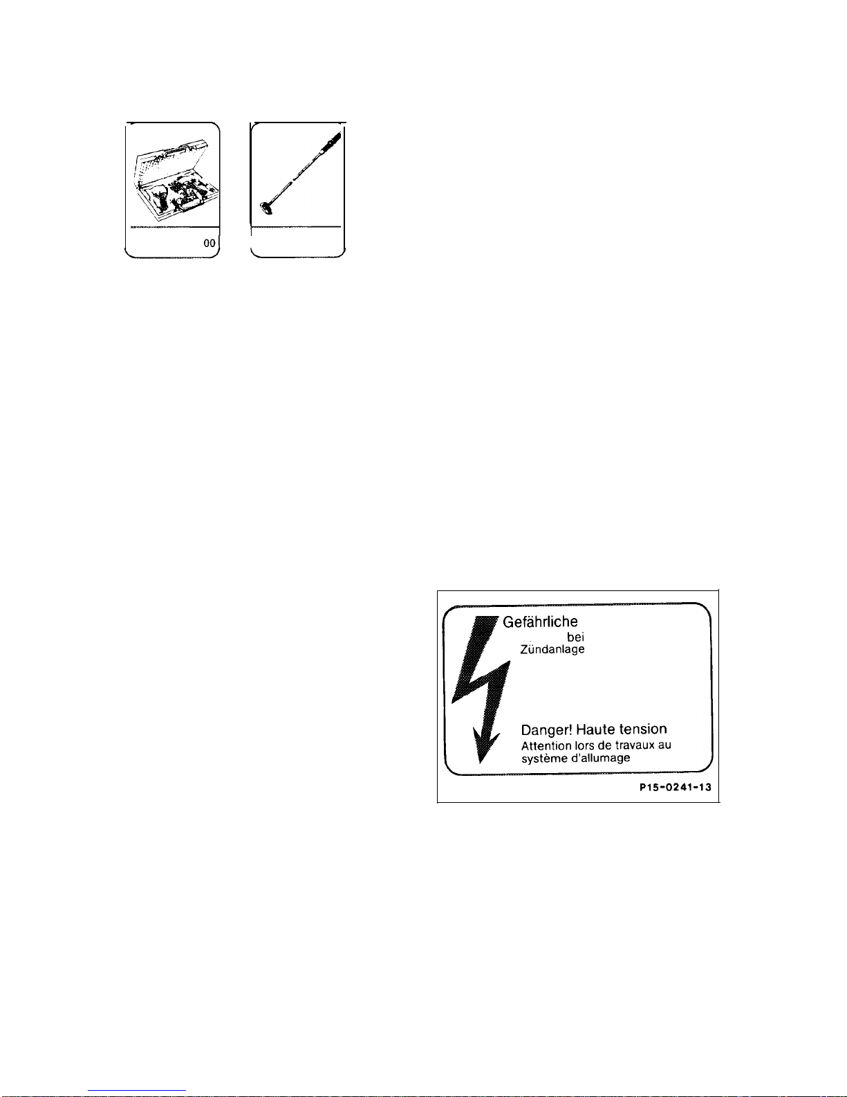
Special tools
001 589 76 21 001
1124589366300
Notes
Test compression pressure at normal operating
temperature.
If the minimum compression pressure is not
reached, test cylinder leaktightness (01-015).
Unscrew all the spark plugs for testing.
Turn crankshaft with starter and compression
pressure recorder.
Warning!
The engines are equipped with an ignition
system with variable ignition characteristics
(EZL).
Because of high ignition voltage, it is very
dangerous to touch components of the ignition
system (ignition coil, ignition cables, spark plug
connector, plug-on unit)
when
l
the engine is running,
l
the engine is started,
l
the key in the steering lock is in position
2
and the engine is cranked by hand.
’
Geftihrliche Hochspannung!
Vorsicht
bei
Arbeiten an der
Danger! High voltage
Observe caution when working
on the ignition system
PIS-0241-13
01.0904 . 01012
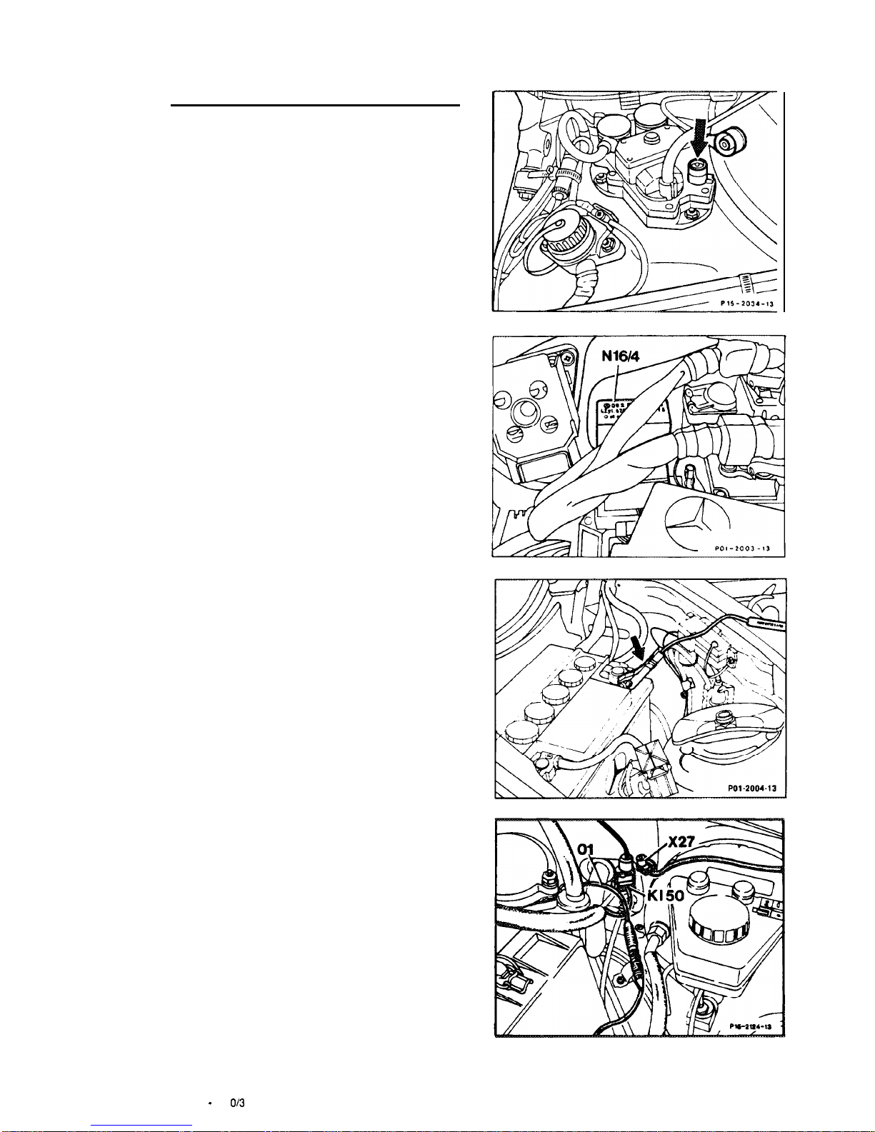
Testing
1
Switch off ignition. Detach connector from
ignition distributor pickup (green cable on control
module) (arrow).
Caution!
On injection engines, detach the fuel pump relay
module (N1614) before turning the crankshaft to
ensure that no fuel is injected.
Model 201
2
Connect compression pressure recorder.
This is done by clamping one of the two alligator
clamps (arrow) of the compression pressure
recorder, Part No. 001 589 76 21 00, to the
positive terminal post of the battery.
3
Detach connector (X27) from plug
connection (terminal 50).
4
Plug in connector of adapter cable (01),
Part
No. 124
589
36
63 00.
Model 201
01.0904 - 01
o/3
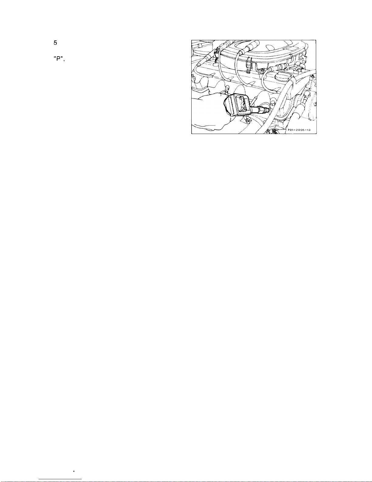
5
motor, in idle position, selector
“P”,
and parking brake applied
and soot are ejected.
Crank engine several times with starter
lever in position
so that residues
6
To test each cylinder, press the compression
pressure recorder into the spark plug hole of the
particular cylinder and, with the throttle valve
fully opened, crank engine approx. 8 revolutions.
Test all the cylinders in this way.
7
Blow out spark plug recesses with
compressed air. Remove any residues on the
tapered sealing seat.
01.0904 - 01014
01-015
Testing cylinder leaktightness
Data
Total pressure loss
max. 25%
At valves and cylinder head gasket
max. 10%
At pistons and piston rings
max.
20%
Tightening torque
Nm
Spark plugs
Special tools
Commercial tool
Cylinder leaktightness tester
e. g. Bosch, EFAW 210 A
Sun, CLT 228
Testlng
1
Run engine until at normal operating
temperature.
2
Blow out spark plug recesses with
compressed air.
3 Remove spark plugs.
01.0904 - 01511
4
Top off coolant and leave filler opening at
coolant expansion tank open.
5
Remove oil filler cap.
6
Remove air filter (09-400 or
09-410).
7
Connect cylinder leaktightness tester to a
compressed air system and calibrate tester.
8
Position piston of No. 1 cylinder to ignition
TDC. This is done by turning the crankshaft with
a tool combination consisting of wrench socket
(27 mm,
l/2”
square) and reversible ratchet
handle, at the central bolt (front of crankshaft).
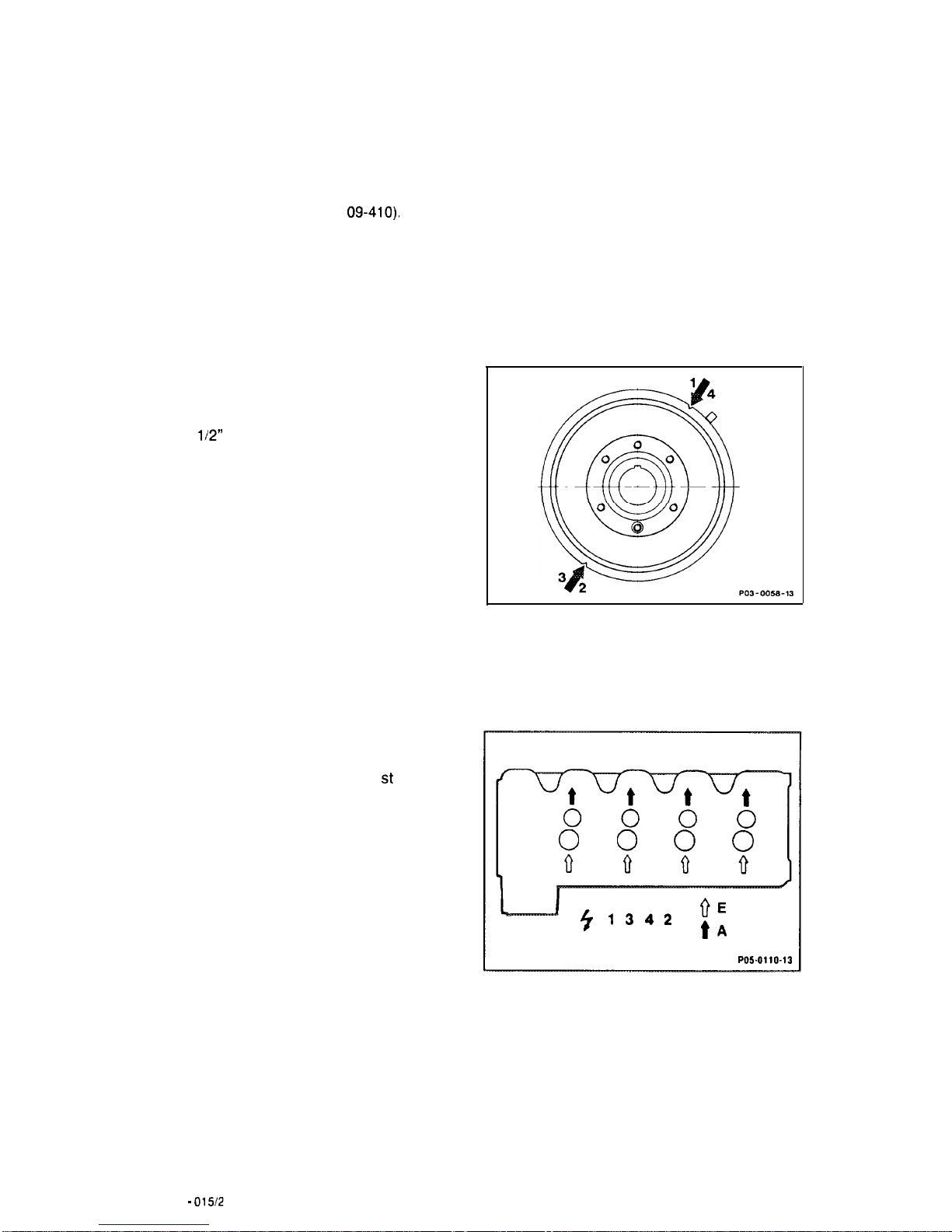
Note
The respective pistons are in the TDC position
when the markings shown in the drawing
opposite on the vibration damper or on the belt
pulley are below the TDC pointer.
9 Open throttle fully.
10 Screw connection hose into the 1 st spark
plug bore and attach to the connecting hose of
the tester.
The crankshaft must not turn when performing
this step.
11 Read off pressure loss at tester.
12 Determine by listening whether the pressure
escapes through intake manifold, exhaust, oil
filler opening, spark plug bore of adjacent
cylinder or coolant filler opening.
-_-.-I
‘r
1342
VE
tA
P05.0110-13
13 Test all the cylinders in the firing order.
01.0904 - 015/2

Notes
It is possible that the piston ring gaps of
individual pistons are directly above each other
which falsifies the test result.
In cases of doubt, allow vehicle to run and test
cylinder leaktightness once again after some
time.
After spraying oil onto the piston crown, it is
possible to determine whether the leak exists at
the piston rings or at the valves or the cylinder
head gasket.
01.0904 - 015/3
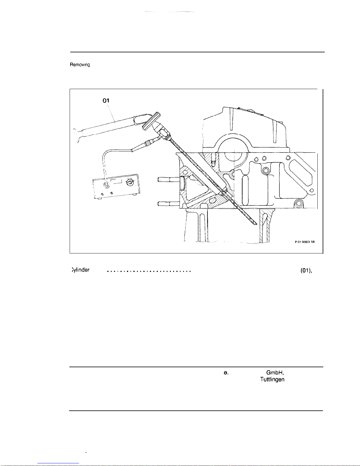
01-020
Illuminating cylinders
Preceding work:
Removing spark plugs (15-018).
C
iylinder (01)
. . . . . . . . . . . . . . . . . , . . . . . . . .
illuminate with cylinder inspection lamp (Ol),
distinguish between “optical rub marks and
seizing rub marks”.
“Optical rub marks” may result from the ring
gap. Traces of honing are still visible, engine in
order.
“Seizing rub marks”; honing marks no longer
visible, recondition engine.
Commercial tool
Cylinder inspection lamp
8.
g. Karl Storz
GmbH,
D-7200
Tuttlingen
Motoskop TW (cold light) with
lens probes 103 26 CW
(570 mm) and 103 26 CT (210)
01 0904 - 02011
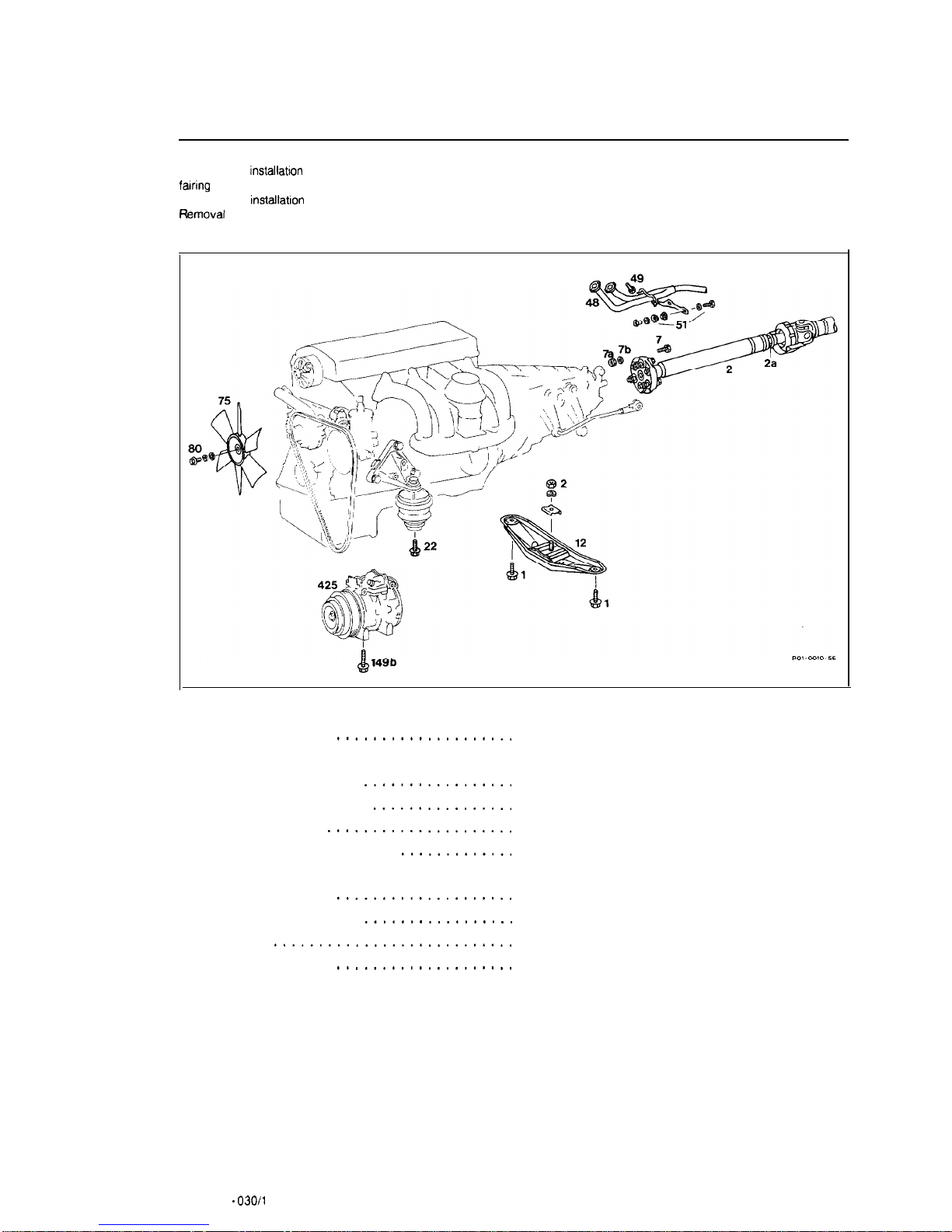
01-030
Removal and installation of englne
Preceding work:
Removal and
installation
of bottom engine compartment
fairing
(01-006).
Removal and
installation
of air filter (09-400 or 09-410).
R
emoval and installation of radiator (20-420).
Battery positive cable
....................
Fan (75)
.............................
Alternator cable connector
.................
Lines for pressure oil pump
................
Cover for evaporator
.....................
Cover for engine wiring harness
.............
Starter wiring harness
....................
Terminal block terminal 50
.................
Terminal 30
...........................
Engine wiring harness
....................
disconnect, connect.
remove, install, 25 Nm.
detach (step 3).
detach, attach (step 4).
insert (step 5).
remove at component partition wall
(steps 6 and 7).
remove, install (step 8).
disconnect, connect (step 9).
disconnect, connect at terminal block (step 10).
disconnect, connect at the individual
connections (steps
11
to 18).
01.0904 .
030/l

Fuel evaporation system
..................
Ground cable
..........................
Accelerator control
......................
Fuel lines
.............................
Coolant hose, heater supply line
............
Vacuum line, brake booster
................
Air conditioning compressor (425)
...........
Engine hoist
...........................
Guard plate
...........................
Exhaust system (48)
. . . . . . . . . . . . .
Lambda sensor
........................
Engine supporting bracket
(12)
.............
Drive shaft to transmission (2) . . . . . . . . .
.
Clamping nut (2a)
.......................
Speedometer shaft
.....................
Ground cable at transmission
...............
Shift rods at transmission
.................
Cable connector for starter lockout, backup
light switch
............................
Cable for
kickdown
solenoid valve
...........
Front engine mounting (22)
................
detach, attach (step 19).
unbolt, bolt on at intake manifold (step 20).
disconnect, connect
Bowden
cable, adjust
(step 21).
detach, attach (step 22).
detach, attach (step 23).
detach, attach (step 24).
Note
On vehicles with air conditioning, the
AC
compressor can be unbolted with the lines
connected and without draining the system
(steps 25 to 34).
attach to suspension lugs, detach (step 35).
insert between component compartment and
engine, remove (step 37).
unbolt at exhaust manifold and transmission
mount (51) bolt on (steps 38 and
39)
25 Nm.
remove, install (step 40).
unbolt, bolt on (step 42).
Tightening torques:
Bolt (1) 25 Nm,
Nut (2)
70 Nm.
detach, attach, replace self-locking nuts (7a)
(step 44).
loosen, tighten (step
45),
45 Nm.
disconnect, connect to transmission (step 46).
disconnect, connect (step 47).
detach, attach (step 48).
unplug, plug in (step 49).
disconnect, connect (step 50).
unbolt, bolt on at bottom (step
51),
40 Nm.
01
0904 -03012
Engine with transmission . . . . . . . . . . . . . . .
.
lift out, insert (step 52).
Lines, hoses and engine mounts. . . . . . . .
.
examine for signs of wear, replace if necessary.
Examine antifreeze protection, adjust to correct
level if necessary. Test leaktightness.
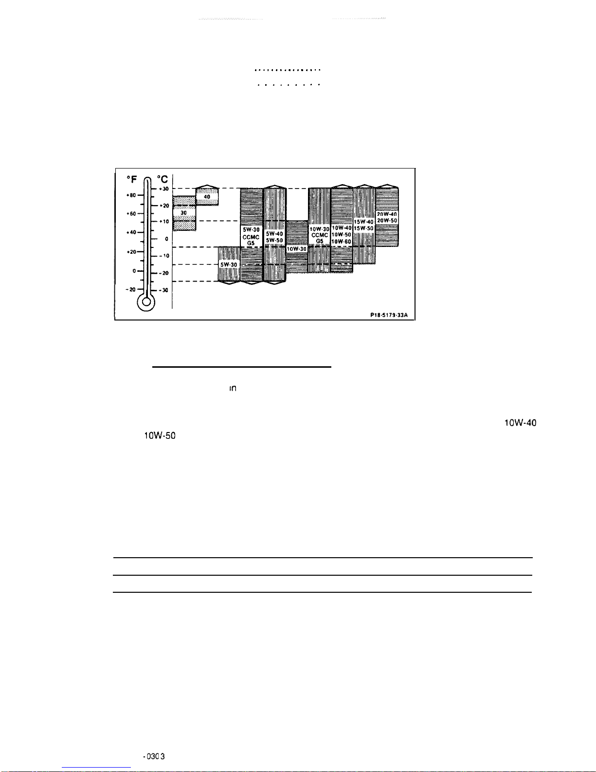
Viscosity grades for engine oils according to SAE
Adhering to the SAE grades In accordance with ambient temperatures would result in frequent oil
changes. Consequently, the temperature ranges are merely guidelines, which can be exceeded in the
upper or lower limits for brief periods.
In moderate climatic zones SAE 30 may be used from the spring on for all engine models. SAE
low-40
or SAE
low-50
may be used as an all-seasons oil for all gasoline engines.
Refer to the most current “Factory Approved Service Products” for further information regarding
specified viscosity grades and approved engine oils.
Oil capacity in liters
(refer to Factory Approved Service Products for approved engine oils)
Engine (total capacity when refilling)
Engine capacity when changing oil and filter
5.5
5.0
01.0904
-
030 3
Tightening torques
Nm
Fan to engine coolant pump
25
Exhaust pipe to exhaust manifold
Exhaust bracket to transmission
Hexagon bolt of belt pulley to power steering pump
25
25
25
Bracket for
A/C
compressor to oil sump
10
Bracket for AC compressor to AC compressor
25
V bracket servo pump -engine supporting bracket - AC compressor
25
Servo pump to supporting bracket
25
AC
compressor to supporting bracket
30
Propeller shaft to transmission
45
Clamping nut to spline end of propeller shaft
45
Ground cable to transmission
45
Engine mount to axle carrier
40
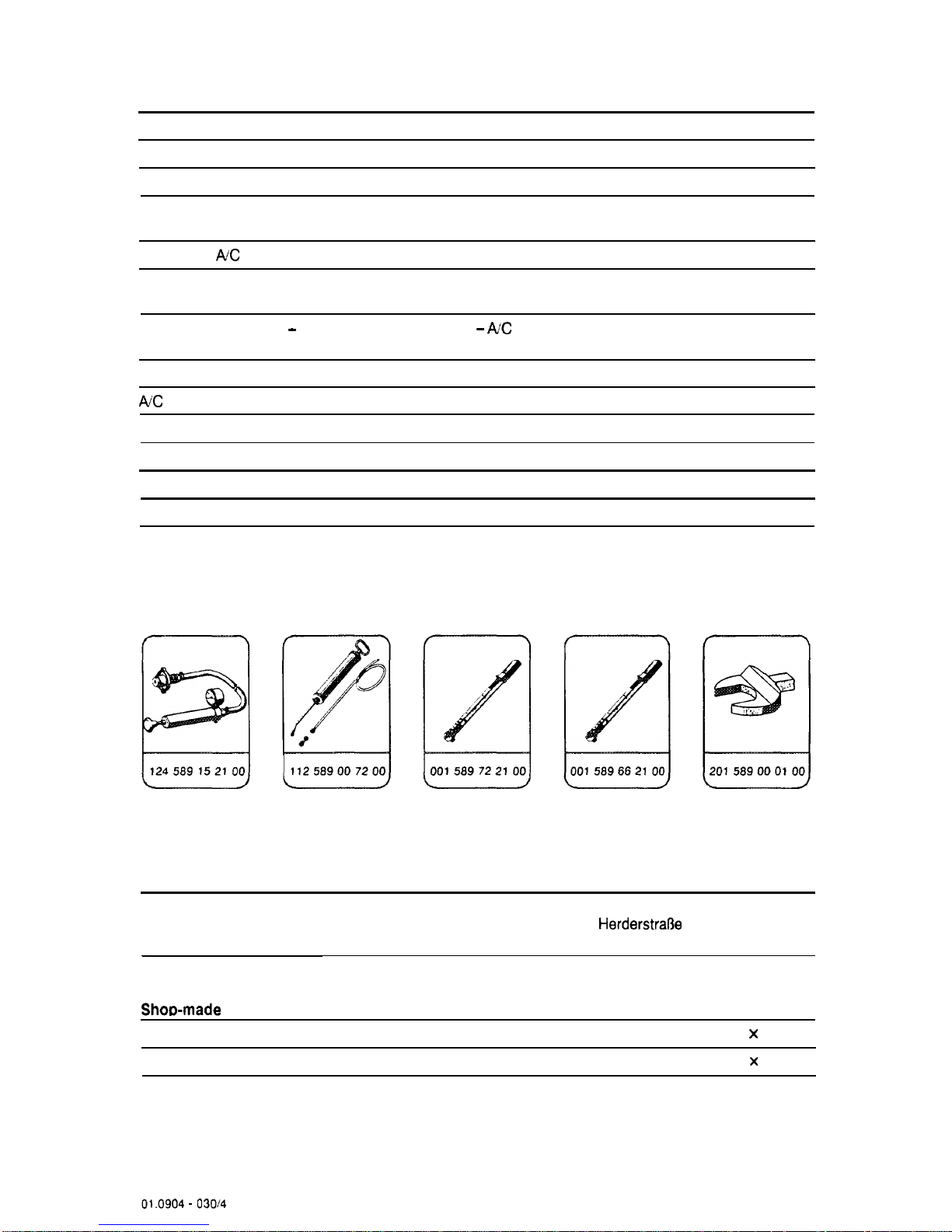
Special tools
Commercial tool
Engine hoist No. 3188 self-locking e. g. Messrs. Backer
HerderstraOe
D-5630 Remscheid
Shoe-made
tools
Guard plate for radiator/evaporator
Dimensions approx. 480 X 600 X 1
Metal panel for component compartment wall
Dimensions approx. 320 X 380 X 1
01.0904 -
03014
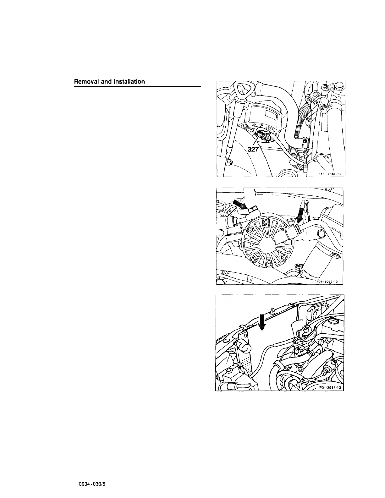
Note
Remove and install engine together with
transmission.
1
Disconnect battery negative terminal,
connect.
2 Remove fan. install.
3
Unplug cable connector (327) at alternator,
plug in.
4
Detach lines for pressure oil pump at
cylinder head, connect (arrows).
5
If equipped with air conditioning: install guard
plate (arrow) to evaporator of air conditioning
system.
01
0904 -
030!5
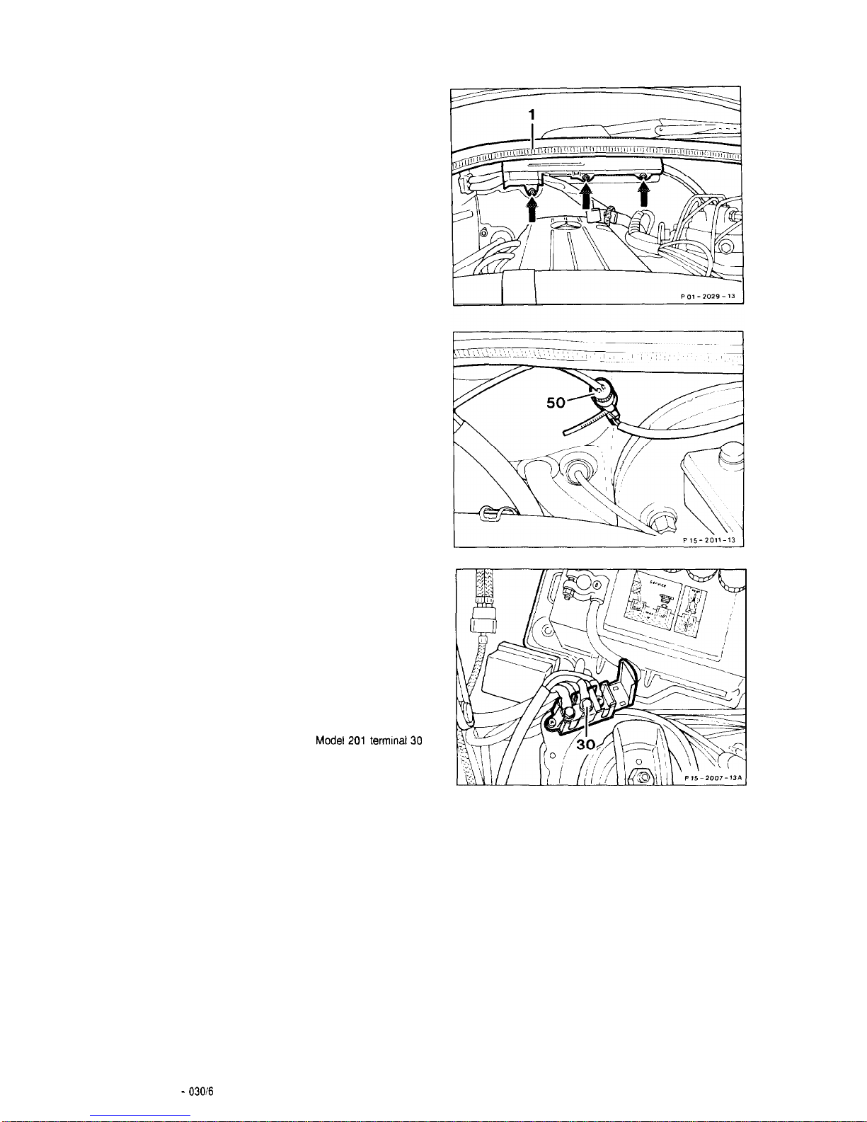
7
On Model 201, pull off rubber strip (1) above
fire wall.
Take out clips (arrows), fold fixture upwards.
Model201
9
On Model 201, unplug cable connector (50)
at the plug connection, plug in.
Model201
10 Unbolt battery positive terminal. Disconnect
terminal (30) at cable connector and pull cable
through component compartment wall and place
over engine.
Model201termlnal30
01.0904 -
03016
 Loading...