


USER’S MANUAL
IOtech 640 & 650 Series
Dynamic Signal Analyzers for Vibration Analysis and Monitoring
IOtech 640 & 650 Series
Project 1142 rev 2.1
*372538B-01*
372538B-01
Requires one of the following Operating Systems:
Windows 2000
Windows XP
Windows Vista
IOtech
25971 Cannon Road Cleveland, OH 44146-1833
(440) 439-4091 Fax: (440) 439-4093 sales@iotech.com productsupport@iotech.com www.iotech.com
IOtech
25971 Cannon Road
Cleveland, OH 44146-1833
Phone: (440) 439-4091
Fax: (440) 439-4093 E-mail: sales@iotech.com
E-mail: productsupport@iotech.com Internet: www.iotech.com
Warranty Information
Your IOtech warranty is as stated on the product warranty card. You may contact IOtech by phone, fax machine, or e-mail in regard to warranty-related issues.
Phone: (440) 439-4091, fax: (440) 439-4093, e-mail: sales@iotech.com
Limitation of Liability
IOtech, Inc. cannot be held liable for any damages resulting from the use or misuse of this product.
Copyright, Trademark, and Licensing Notice
All IOtech documentation, software, and hardware are copyright with all rights reserved. No part of this product may be copied, reproduced or transmitted by any mechanical, photographic, electronic, or other method without IOtech’s prior written consent. IOtech product names are trademarked; other product names, as applicable, are trademarks of their respective holders. All supplied IOtech software (including miscellaneous support files, drivers, and sample programs) may only be used on one installation. You may make archival backup copies.
CE Notice
Many IOtech products carry the CE marker indicating they comply with the safety and emissions standards of the European Community. As applicable, we ship these products with a Declaration of Conformity stating which specifications and operating conditions apply.
Warnings, Cautions, Notes, and Tips
Refer all service to qualified personnel. This caution symbol warns of possible personal injury or equipment damage under noted conditions. Follow all safety standards of professional practice and the recommendations in this manual. Using this equipment in ways other than described in this manual can present serious safety hazards or cause equipment damage.
This warning symbol is used in this manual or on the equipment to warn of possible injury or death from electrical shock under noted conditions.
This ESD caution symbol urges proper handling of equipment or components sensitive to damage from electrostatic discharge. Proper handling guidelines include the use of grounded anti-static mats and wrist straps, ESD-protective bags and cartons, and related procedures.
This symbol indicates the message is important, but is not of a Warning or Caution category. These notes can be of great benefit to the user, and should be read.
In this manual, the book symbol always precedes the words “Reference Note.” This type of note identifies the location of additional information that may prove helpful. References may be made to other chapters or other documentation.
Tips provide advice that may save time during a procedure, or help to clarify an issue. Tips may include additional reference.
Specifications and Calibration
Specifications are subject to change without notice. Significant changes will be addressed in an addendum or revision to the manual. As applicable, IOtech calibrates its hardware to published specifications. Periodic hardware calibration is not covered under the warranty and must be performed by qualified personnel as specified in this manual. Improper calibration procedures may void the warranty.
Quality Notice
IOtech has been an ISO 9001 registered firm since 1996. Prior to shipment, we thoroughly test our products and review our documentation to assure the highest quality in all aspects. In a spirit of continuous improvement, IOtech welcomes your suggestions.
IOtech 640 & 650 Series User’s Manual |
878893 |
iii |

CAUTION
Using this equipment in ways other than described in this manual can cause personal injury or equipment damage. Before setting up and using your equipment, you should read all documentation that covers your system. Pay special attention to Warnings and Cautions.
Note: During software installation, Adobe® PDF versions of user manuals will automatically install onto your hard drive as a part of product support. The default location is in the Programs group, which can be accessed from the Windows Desktop. Initial navigation is as follows:
Start [on Desktop] Programs IOtech 600 Software
You can also access the PDF documents directly from the data acquisition CD by using the <View PDFs> button located on the opening screen.
Refer to the PDF documentation for details regarding both hardware and software.
A copy of the Adobe Acrobat Reader® is included on your CD. The Reader provides a means of reading and printing the PDF documents. Note that hardcopy versions of the manuals can be ordered from the factory.
640_650 Users Manual.pdf
The user’s manual includes chapters pertaining to configuration, connectors, analog signals, digital I/O, triggers, CE compliance, troubleshooting, specifications, and a brief look at related out-of-the-box software. The following PDFs are companion documents and should be referred to as applicable to your system.
640e_650e Quick Start.pdf Quick Start for Ethernet models 640e & 650e
640u_650u Quick Start.pdf Quick Start for USB2.0 models 640u & 650u eZ-Analyst.pdf
eZ-TOMAS.pdf eZ-Balance.pdf eZ-NDT.pdf
iv |
IOtech 640 & 650 Series User’s Manual |
878893 |
About the Documentation
In addition to the user’s manual there are several PDF documents of importance. During software installation, Adobe® PDF versions of documents are automatically installed onto your hard drive. The default location is in the Programs group, accessible through the Windows Desktop. The documents may also be viewed directly from the data acquisition CD via the <View PDFs> button located on the CD’s opening screen.
Unless you have hardcopy equivalents, you should refer to the PDF version documents for details regarding both hardware and software.
The IOtech 640 & 650 Series User’s Manual consists of the following chapters. The chapters contain references to other documents as applicable.
Quick Start, IOtech 640e and 650e
Quick Start, IOtech 640u and 650u
Chapter 1 – What are IOtech 640 & 650 Series Devices?
Chapter 2 – Block Diagram and General Comments
Chapter 3 – Connectors, Indicators, and Cables
Chapter 4 – Configuring Ethernet Models 640e and 650e
Chapter 5 – Configuring USB Models 640u and 650u
Chapter 6 – Analog Signals
Chapter 7 – Digital I/O
Chapter 8 – CE Compliance and Noise Considerations
Chapter 9 – Troubleshooting and Customer Support
Chapter 10 – Software Options
Chapter 11.a – Specifications, IOtech 640 & 650 Series
Chapter 11.b – Specifications, Data Plots
Appendices
Appendix A – Using the Daq Configuration Applet
Appendix B – TCP/IP and Resource Tests
Appendix C – Transducer Electronic Data Sheets (TEDS)
Glossary
CAUTION
Using the equipment in ways other than described in the documentation can cause personal injury or equipment damage. Pay attention to all Warnings and Cautions.
Reference Notes:
Information (not available at the time of publication), will be made available in ReadMe files, or in supplemental documentation.
Note: A copy of the Adobe Acrobat Reader® is included on your CD. The Reader provides a means of reading and printing the PDF documents. Note that hardcopy versions of the manuals can be ordered from the factory.
878893 |
IOtech 640 & 650 Series User’s Manual v |

This page is intentionally blank.
vi |
IOtech 640 & 650 Series User’s Manual |
878893 |

Table of Contents
Quick Start, IOtech 640e and 650e (324539B-01)
Quick Start, IOtech 640u and 650u (324540B-01)
Chapter 1 – What are IOtech 640 & 650 Series Devices? Chapter 2 – Block Diagram and General Comments
Chapter 3 – Connectors, Indicators, and Cables
Front Panel Connectors and Indicators …… 3-1 Rear Pannel Connectors …… 3-2
Unit Underside …… 3-3 Accessories …… 3-4
Chapter 4 – Configuring Ethernet Models 640e and 650e
System Requirements …… 4-1 Software Installation …… 4-2
Ethernet Connection and System Power-up …… 4-3 Connecting Data Acquisition Signal Lines …… 4-14
Chapter 5 – Configuring USB Models 640u and 650u
System Requirements …… 5-1
Software Installation …… 5-2
USB Connection and System Power-up …… 5-3
Connecting Data Acquisition Signal Lines …… 5-6
Chapter 6 – Analog Signals
Introduction …. 6-1 Analog Common …… 6-3
Current Source (IEPE) with Transducer Fault Detection ……. 6-3 Input Coupling …… 6-3
Low-Pass Anti-Aliasing Filter …… 6-4
Transducer Electronic Data Sheet (TEDS) Support (eZ-Analyst only) …… 6-4 Output BNC (640 units only) …… 6-5
Analog Triggers …… 6-5 Using Accelerometers …… 6-6
Sound and Vibration Sensors – Supplemental Information …… 6-9
Chapter 7 – Digital I/O (Applies only to eZ-TOMAS and eZ-NDT)
Chapter 8 – CE Compliance and Noise Considerations
Overview …… 8-1
CE Standards and Directives …… 8-1 Safety Conditions ……8-2 Emissions/Immunity Conditions …… 8-3
Using Shielded BNC Connectors for CE Compliance …… 8-3 CE Rules of Thumb for 640 and 650 Series Devices …… 8-3 Noise Considerations …… 8-4
IOtech 640 & 650 Series User’s Manual |
878893 |
vii |

Chapter 9 – Troubleshooting and Customer Support
Electrostatic Discharge (ESD), Handling Notice…… 9-1
Product Care …… 9-1
ReadMe Files and the Install CD-ROM …… 9-2
Ethernet Problems (640e and650e only) …… 9-2
Customer Support …… 9-5
Chapter 10 – Software Options eZ-Analyst …… 10-2 eZ-TOMAS …… 10-3 eZ-Balance …… 10-4
eZ-NDT …… 10-5
Chapter 11.a Specifications, IOtech 640 & 650 Series
11.b Specifications, Data Plots
Appendices
Appendix A – Using the Daq Configuration Applet
Appendix B – TCP/IP and Resource Tests
Appendix C – Transducer Electronic Data Sheets (TEDS) (eZ-Analyst only)
Glossary
viii |
878893 |
IOtech 640 & 650 Series User’s Manual |
IOtech 640e & 650e |
Quick Start |
Ethernet Dynamic Signal Analyzers for Vibration Analysis & Monitoring
Before you get started
Verify that you have the following items.
• 640e or 650e
• TR-2U Power Supply
• Ethernet Patch Cable
• Ethernet jack [on PC or on a hub connected to the Ethernet].
• Dynamic Signal Analysis CD
• License Keys for purchased software;
e.g., eZ-Analyst, eZ-TOMAS, eZ-Balance, eZ-NDT
• Monitor: SVGA, 1024 x 768 screen resolution
• Windows 2000 and Windows XP users:
PC with Intel™ Pentium, 1 GHz or equivalent; 512 MB memory; 10 GB disk space
• Windows Vista users:
PC must be Windows Vista Premium Ready
Step 1 - Install Software
1.Close all running applications on the host PC.
2.Insert the Dynamic Signal Analysis CD into your CD-ROM drive and wait for the CD to auto-run. An Opening Screen will appear. As an alternative, you can download software from: www.iotech.com/ftp.html
3.Click the <ENTER SETUP> button.
Note: If you are downloading software from our website, follow instructions provided there.
4.From the hardware selection screen [which follows a licensing agreement], select the 640, 650 product-line from the drop-down list and follow the on-screen instructions.
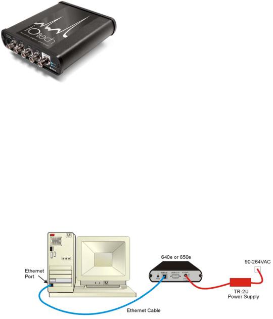
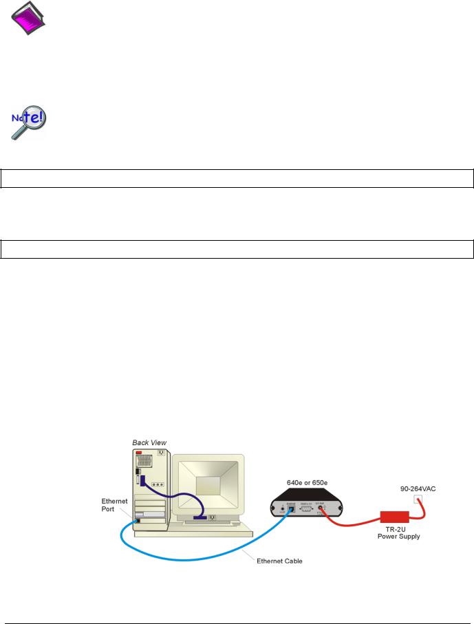
Step 2 - Connect the 640e or 650e to the Ethernet
In this scenario a 640e or 650e is connected directly to an Ethernet port on a host computer. Please consult your user’s manual (located in PDF format on the CD) should you need information regarding the other network types.
1.Connect the Ethernet cable to the Ethernet jack on the 640e [or 650e].
2.Connect the other end of the Ethernet cable to the Ethernet jack on the host computer or network hub.
Step 3 - Connect the 640e or 650e to Power
1.Connect the power supply cable from the TR-2U to the External Power connector of the 640e [or 650e].
2.Connect the TR-2U plug to a standard AC outlet. The 640e [or 650e] Power LED will light up.
324539B-01
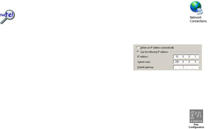
Step 4 - Configure Computer Network Settings
Applies to “dedicated networks” only. See user’s manual in regard to other network types.
We recommend that you discuss this procedure with your Network Administrator before proceeding. Note that the 640e and 650e Ethernet ports typically require 30 seconds after power-up [to configure] before the unit can be accessed via the network.
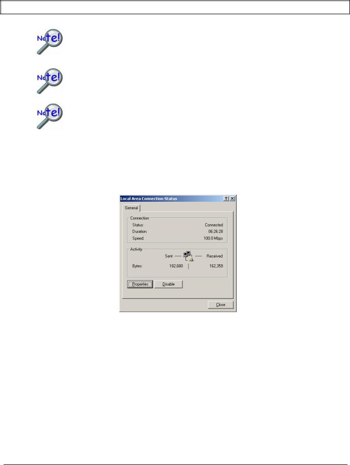
1.Open the Control Panel by navigating from the Windows Desktop: Start Menu Settings Control Panel.
2.Double-click the “Network Connections” icon.
3.Double-click the icon for the network that the 640e [or 650e] is connected to.
4.In the “Local Area Connection Status” box, click on the <Properties> button. The “Local Area Connection Properties” box will appear.
5.Double-click the “Internet Protocol (TCP/IP)” component. The “Internet Protocol (TCP/IP) Properties” box will appear.
6.Select the “Use the following IP Address” radio button. (See figure at left).
7.Set the IP address field to 10.0.0.x , where x is some number from 1 to 254.
Make sure that each computer and each device on the dedicated network has a unique IP address.
8.Set the Subnet mask to 255.0.0.0. Note that the remaining fields can be left as is.
9.Click <OK> on follow-up screens to exit.
Internet Protocol (TCP/IP) Properties
(Partial View)
Step 5 - Configure & Test the System with the Daq Configuration Applet
1.Open the Daq Configuration Applet.
a.Navigate from the Windows’ Desktop: Start Menu Settings Control Panel
b.From the Control Panel, double-click the Daq Configuration icon.
2.Add the 640e or 650e to the list of installed devices.
a.Click the <Add Device> button. The “Select Device Type” box will appear.
b.Select the 640e or 650e from the list of devices, as applicable.
c.Click the <OK> button. The “Properties” box will appear for the selected device.
d.Enter the Serial Number of the 640e [or 650e].
e.Select the “Auto IP Setting” radio button. The IP Address of the 640e [or 650e] will be calculated automatically and displayed in the IP Address field.
3.Test the System.
a.Click the “Test Hardware” tab.
b.Click the <TCP/IP Test> button. This tests the Transmission Control Protocol / Internet Protocol.
c.Upon completion of the TCP/IP test, click the <Resource Test> button.
When testing, if the unit does not respond within 30 seconds perform the following steps: 1) reboot the system, 2) upon power-up, re-open the Daq Configuration applet,
3) select another configuration setting, 4) reinitiate the test.
Step 6 - Connect Data Acquisition Signal Lines
Prior to making signal connections review the Specifications chapter of your user’s manual to ensure that your intended signal inputs do not exceed the specified limits. The manual is included in PDF format on your CD.
*324539B-01*
324539B-01
IOtech, 25971 Cannon Road, Cleveland, OH 44146-1833
Ph: (440) 439-4091 Fax: (440) 439-4093 productsupport@iotech.com |
Internet: www.iotech.com |
Printed in Hungary
IOtech 640u & 650u Quick Start
USB2.0 Dynamic Signal Analyzers for Vibration Analysis & Monitoring
Before you get started
verify that you have the following items.
• 640u or 650u
• USB Cable
• USB2.0 port [on PC]
• Dynamic Signal Analysis CD
• License Keys for purchased software;
e.g., eZ-Analyst, eZ-TOMAS, eZ-Balance, eZ-NDT
• Monitor: SVGA, 1024 x 768 screen resolution
• Windows 2000 and Windows XP users: Intel™ Pentium, 1 GHz or equivalent; 512 MB memory; 10 GB disk space
• Windows Vista users:
PC must be Windows Vista Premium Ready
Step 1 - Install Software
1.Close all running applications on the host PC.
2.Insert the Dynamic Signal Analysis CD into your CD-ROM drive and wait for the CD to auto-run. An Opening Screen will appear. As an alternative, you can download software from: www.iotech.com/ftp.html
3.Click the <ENTER SETUP> button.
Note: If you are downloading software from our website, follow instructions provided there.
4.From the hardware selection screen [which follows a licensing agreement], select the 640, 650 product-line from the drop-down list and follow the on-screen instructions.
Step 2 - Connect the 640u or 650u to the Computer
1.Using a USB cable, connect the 640u [or 650u] to a USB2.0 port on the computer. USB2.0 port is required.
2.Follow the computer screen prompts as directed to allow the computer to detect your new hardware.
Note:
Power LED: The “Power” LED blinks during device detection and initialization; then remains on solid as long as the module has power. If there is insufficient power the LED will go off.
Active LED: This LED is on whenever active communication is taking place between the 640 [or 650] and the host PC. Note that the Active LED will be on solid during a data acquisition.
324540B-01
Step 3 - Connect Data Acquisition Signal Lines
Prior to making signal connections review the Specifications chapter of your user’s manual to ensure that the input signals do not exceed the specified limits. The manual is included in PDF format on the CD.
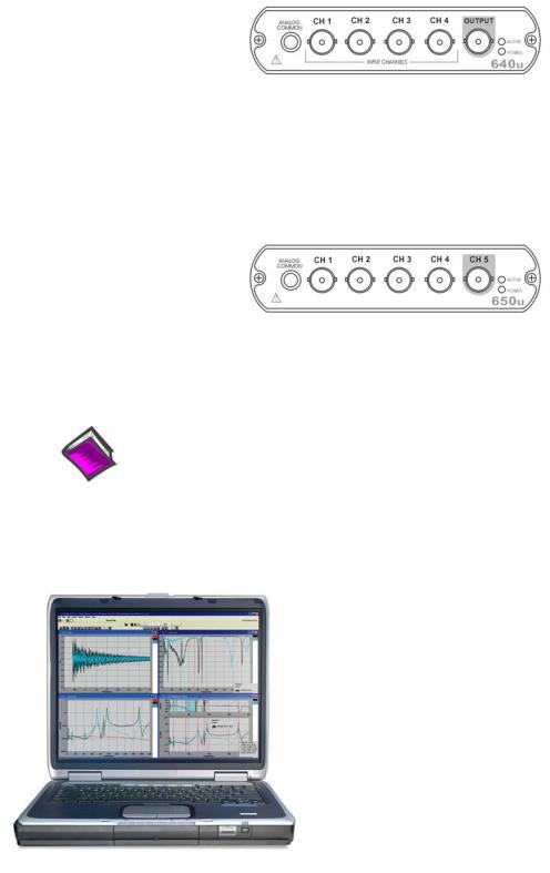
The 640u
4 analog channel inputs (CH1 through CH4) via front panel BNC connectors. 1 analog output via the fifth front panel BNC connector.
8 digital I/O lines via rear panel DB9 connector, as discussed in Chapter 3 of the user’s manual.
The 650u
5 analog channel inputs (CH1 through CH5) via front panel BNC connectors.
8 digital I/O lines via rear panel DB9 connector, as discussed in Chapter 3 of the user’s manual.
Reference Notes:
Adobe Acrobat PDF versions of documents pertaining to IOtech 640u and 650u are automatically installed onto your PC’s hard-drive as a part of product support at the time of software installation. The default location is the Programs group. It can be accessed via the Windows Desktop Start Menu.
IOtech, Inc.
25971 Cannon Road
Cleveland, OH 44146-1833
Phone: (440) 439-4091
Fax: (440) 439-4093
E-mail: sales@iotech.com E-mail: productsupport@iotech.com
Internet: www.iotech.com
*324540B-01*
324540B-01
Printed in Hungary
What are IOtech 640 and 650 Series Devices ? |
1 |
|
|
* The actual model number includes an “e” or “u” to indicate Ethernet or USB version.
IOtech 640 and 650 Series Panels
IOtech 640 and 650 Series devices are dynamic signal analyzers used for monitoring and analyzing machinery and structures in regard to sound, vibration, and rotation. The device hardware is the signal conditioning and acquisition engine, while the software defines the specific analysis and monitoring features of the system. Since the software [in the host PC] determines which capabilities will be used, it is easy to upgrade the system and add more capabilities over time.
There are currently 4 models in the 640 and 650 product line. These are 640e, 640u, 650e, and 650u, where
“e” indicates Ethernet Interface and “u” indicates USB2.0 Interface. The following matrix compares model features.
|
|
Analog |
|
|
High Pass |
Model |
Interface |
Input |
|
|
Filter |
|
|
Channels |
|
|
Cutoff |
640e |
Ethernet |
|
|
|
|
10/100BaseT |
4 |
|
|
1.0 Hz |
|
|
|
|
|||
640u |
USB2.0 |
|
|
|
|
650e |
Ethernet |
|
|
|
|
|
|
|
|
||
10/100BaseT |
5 |
|
|
0.1 Hz |
|
|
|
|
|||
650u |
USB2.0 |
|
|
|
|
|
|
|
|
|
|
|
Analog |
|
|
|
Analog |
|
|
Digital I/O |
|
|
External |
|
|
Input |
|
|
|
Output |
|
|
|
|
Power |
|
|
|
|
|
|
|
|
Channels |
|
|
|
|||
|
Range |
|
|
|
Channels |
|
|
|
|
Connector |
|
|
|
|
|
|
|
|
|
|
|
|
|
|
|
|
±10 V |
1 |
|
|
|
|
|
|
|
|||
|
|
|
|
|
|
|
8 |
|
|
6 to 16 VDC |
||
|
|
|
|
|
|
|
|
|
1 amp (max.) |
|||
|
±40 V |
0 |
|
|
|
|
|
|||||
|
|
|
|
|
|
|
|
|||||
|
|
|
|
|
|
|
|
|
|
|
|
|
There are four end-user software application packages available for IOtech 640 and IOtech 650 systems. A brief description of each follows. For more information refer to Chapter 10, Software Options. For detailed information refer to the specific software user’s manual. The data acquisition CD includes PDF versions of the software documents.
eZ-Analyst Used to record and analyze time history data; as well as perform impact (resonance) testing.
eZ-TOMAS Used to acquire, monitor, and analyze rotating machinery data for steady-state and transient conditions.
eZ-Balance Used to field balance multi-plane rotating machinery.
eZ-NDT Used to determine the quality of production parts during the manufacturing process. eZ-NDT is a non-destructive, resonance-based, testing process.
IOtech 640 & 650 Series |
878893 |
What are IOtech 640 & 650 Series Devices? 1-1 |
The IOtech 640e and 650e include a high-speed Ethernet engine powered by a PowerPC processor. The 640u and 650u include a high-speed USB2.0 engine. These Ethernet and USB interfaces allow all acquired data to be transferred to the PC in real time at 630k samples/sec. This means that every acquired data point can reside on the host PC’s hard drive, making re-creation and post acquisition analysis of acquired data as precise as possible. Many other analyzers simply store frequency-domain information, which results in play-back that is less precise than the original real-time measurement. In comparison, the 640 and 650 models transmit all time-domain measurements. This means there is no data loss when analyzing acquired waveforms. Since the data is already on the host PC’s hard drive there is no time lost transferring data.
Another advantage of the 640/650 architecture is that there is virtually no limit to the length of time continuous data can be acquired. Many other systems do not offer continuous time-domain transfer to the PC, and as a result the waveform length is limited by the amount of built-in data storage. In regard to 640/650 units, the only limitation is the amount of available hard disk memory on the host PC, or that which can be accessed by a PC on a network.
• Features of the Dynamic Signal Inputs
o a current source for transducer biasing (ICP) o detection of a transducer fault
o AC coupling: 0.1 Hz for IOtech 650 models; 1.0 Hz for IOtech 640 models; or DC coupling o ±10 V range (IOtech 640 models)
o ±40 V range (IOtech 650 models)
o anti-aliasing filters: 3-pole low pass filter in hardware; set appropriately for each analysis rate o pseudo-differential inputs
o support for TEDS (Transducer Electronic Data Sheet) in eZ-Analyst o any analog input channel can serve as a tach input
ochannel-to-channel phase matching
•For 640u and 650u - Easy Connection to USB2.0-ready Notebooks, Desktop PCs, or USB2.0 Hubs. Note that the USB2.0 port allows a continuous stream of data to be collected and stored in the host PC.
•For 640e and 650e - Easy Connection to Ethernet-ready Notebooks, Desktop PCs, or Ethernet Hubs. Note that the 10/100BaseT Ethernet port allows a continuous stream of data to be collected and stored in the host PC.
•Analog Input Channels: BNC connectors.
•8 Digital I/O Channels: DB9 connector for connection of Digital I/O signal lines. Note: eZ-NDT or eZ-TOMAS software must be used to make use of the Digital I/O.
•Analog Channel Triggering
•Preand Post-Trigger Readings
1-2 What are IOtech 640 & 650 Series Devices? |
878893 |
IOtech 640 & 650 Series |

Block Diagram and General Comments |
2 |
|
|
IOtech 640/650 Series Block Diagram
IOtech 640/650 Series |
878893 |
Block Diagram 2-1 |

General Comments
Ethernet Connection (640e and 650e models only)
IOtech 640e and 650e units transfer the acquired data to the PC via a 10/100BaseT Ethernet connection. The Ethernet connection allows for a continuous stream of data to be collected and stored.
The 10/100BaseT Ethernet interface can be used in a point-to-point application, such as when attached to a notebook PC and used in the field. In this case the 16 Mbytes of buffer storage built into the unit is adequate to ensure that continuous data transfers to the PC can occur without risk of data loss.
The 10/100BaseT Ethernet interface can also be used to connect the unit to a network, presuming the network has enough available bandwidth. The network bandwidth required is a function of the number of signals being measured, and the bandwidth of the signals.
USB Connection (640u and 650u models only)
IOtech 640u and 650u units transfer the acquired data to the PC via a USB2.0 connection. When a computer has a board with USB 2.0 ports, an “Enhanced” USB controller can be found in the Device Manager. The Device Manager will also show two other USB controllers. This is due to the fact that USB2.0 circuitry includes 3 chips [one for the actual USB2.0 capable devices and two for backward USB1.1 compatibility]. Thus a USB 2.0 motherboard can host any USB device (version 2.0 or lower), assuming there are no defects with the board, system, and/or device.
USB Notes:
o IOtech 640u and IOtech 650u require connection to USB2.0
o USB 1.1 (obsolete) hubs will work on USB 2.0 ports, but cannot utilize USB 2.0 capabilities. o Hi-Speed and Full/Low-Speed USB devices can coexist on USB 2.0 hubs.
o USB 2.0 hubs can be used on computers with USB 1.1 ports, but will not exhibit USB 2.0 capabilities.
o Minimize hub use and keep USB cables as short as possible.
o Regardless of the USB hub or port used, if power to the 640u or 650u device is insufficient, connect a TR-2U power adapter to the unit’s External Power jack.
Power
|
640e and 650e units can be powered directly from a 6 to 16 VDC source. They can also be powered from |
|
a 100 to 250 VAC source via its power adapter, which converts the AC to the required DC. |
|
640u and 650u units can be powered solely from a USB2.0 bus, or optionally from a 6 to 16 VDC source |
|
via the external power connector. |
LEDs |
640 and 650 Series modules have 2 LEDs on the front panel. The LEDs function as follows: |
|
Power LED: The “Power” LED blinks during device detection and initialization; then remains on solid |
|
as long as the module has power. If there is insufficient power the LED will go off. |
|
Active LED: This LED is on whenever active communication is taking place between the 640/650 and |
|
the host PC. Note that the Active LED will be on solid during a data acquisition. |
2-2 Block Diagram |
878893IOtech 640/650 Series |

Digital I/O
To make use of the Digital I/O feature the 640 or 650 must be operating with eZ-TOMAS or eZ-NDT. The 8-bits of digital I/O are provided via a rear panel DB9 connector. Each bit is programmable as input or output.
Signal Conditioning
Every input to a 640 or 650 system is software programmable for AC/DC coupling, IEPE source [if AC coupling is selected], and is capable of reading sensor calibration information using Transducer Electronic Data Sheets (TEDS). eZ-Analyst software is required if the TEDS functionality is to be used.
When IEPE sensors are attached, AC coupling with bias current is selected via software. AC coupling without bias is also possible for measuring any AC waveform. DC coupling, which is useful for proximity sensor applications, can also be selected via the software.
For IEPE sensors, indication of an open or shorted fault is available within the eZ-Analyst software application.
Source Output (640 units only)
640e and 640u each include one analog output channel capable of generating continuous waveforms. These waveforms are programmable in regard to amplitude and frequency per product specifications. They can be continuous sine, random, burst, or arbitrary.
IOtech 640/650 Series |
878893 |
Block Diagram 2-3 |

2-4 Block Diagram |
878893IOtech 640/650 Series |
Connectors, Indicators, and Cables |
3 |
|
|
Front Panel Connectors and Indicators …… 3-1
The Rear Pannel …… 3-2
Unit Underside …… 3-3
Accessories …… 3-4
Front Panel Connectors and Indicators
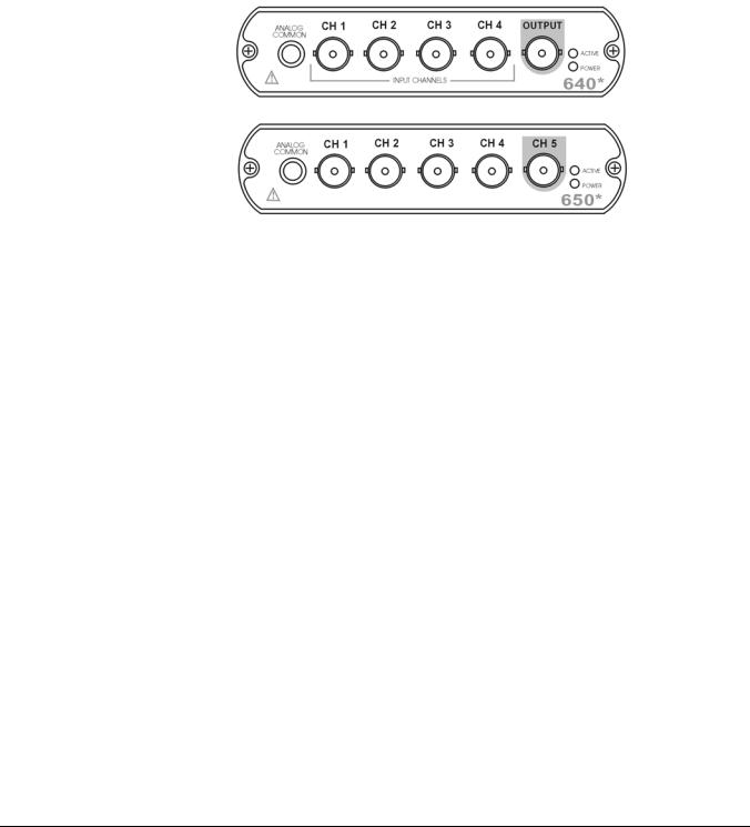
640 and 650 Front Panels
* The actual model number includes an “e” or “u” to indicate Ethernet or USB version.
The 640 and 650 Front Panels include the following connectors and LED indicators.
ANALOG COMMON: Common analog ground.
ANALOG SIGNAL INPUT CHANNELS: These BNC connectors are used for voltage input. The 640 models have 4 input channels. The 650 models have 5 input channels.
The BNC center-conductor is the signal HI and the BNC shell is the signal LO. Each BNC shell is connected to the chassis ground through its own channel-dedicated 1 kΩ resistor. Consequently, the shell is not meant to be driven with respect to earth ground more than ±10V.
An additional consideration pertains to input transducer setup. If the transducer case is effectively earth grounded through its connection to a device under test, there exists the possibility for added measurement noise due to the ground loop that is created. The pseudo-differential input rejects much of this noise. Electrically isolating the transducer from the test device minimizes noise.
OUTPUT (640 units only): The 640 units include a programmable voltage source that can be set in discrete amplitudes (see specifications). The output waveform parameters are controlled by software and can be sine, swept-sine, random, burst, or arbitrary. The output can be used as a test source for the input channels or as excitation for other system elements, such as the amplifier for a shaker table. Detailed information on the excitation source and its operation can be found in the applicable eZ software documentation, e.g., the eZ-Analyst User’s Manual.
NOTE: The output value is not guaranteed unless the Power LED has lit.
640 & 650 Series |
878893 |
Connectors, Indicators, and Cables 3-1 |
Status LEDs 640 and 650 Series modules have 2 LEDs on the front panel. The LEDs function as follows:
Power LED: The “Power” LED blinks during device detection and initialization; then remains on solid as long as the module has power. If there is insufficient power the LED will go off.
Active LED: This LED is on whenever active communication is taking place between the 640 or 650 and the host PC. Note that the Active LED will be on solid during a data acquisition.
Rear Panel Connectors
Rear Panel for 640e & 650e
ETHERNET
Rear Panel for 640u & 650u
USB
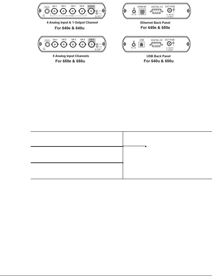
IOtech 640 [or 650] Rear Panels
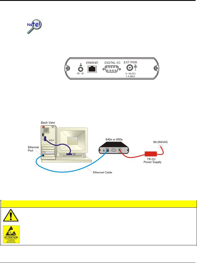
IOtech 640 and 650 “e” and “u” version rear panels are identical aside from their interface ports, with the “e” versions being for Ethernet and the “u” versions being for USB. Both rear panels include a #6-32 chassis ground, a DB9-Digital I/O port, and an External Power connector.
#6-32: Provides a connection point for Chassis Ground via use of a #6-32 machine screw.
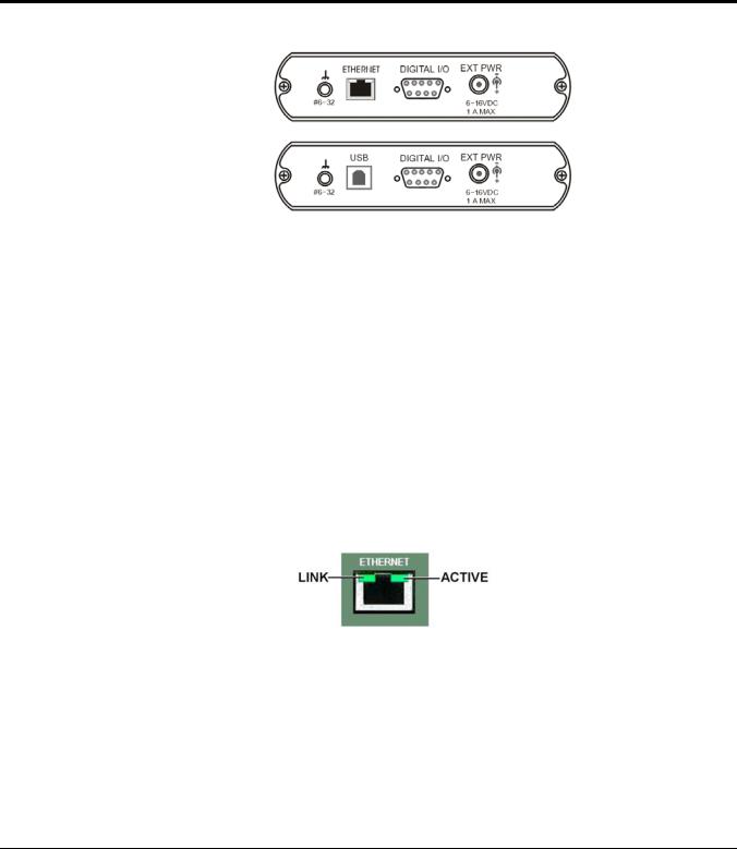
ETHERNET (Applies only to 640e and 650e): The 10/100BaseT Ethernet port can connect to the Ethernet port of the host PC, or to an Ethernet network. Either of two Ethernet patch cables may be used to make the connection. CA-242 is a 1.5 foot cable. CA-242-7 is a 7-foot cable. Note that the Ethernet connector has two built in LEDs that indicate Ethernet status. These are discussed below. Note that the Ethernet cable length must be <10m in order for the system to be CE Compliant.
Two rectangular ETHERNET Status LEDS (LINK and ACTIVE) are built into the frame of the Ethernet jack.
LINK – “ON” indicates that a link via Ethernet exists.
ACTIVE – “ON” indicates that the port is receiving or transmitting traffic.
USB2.0 (Applies only to 640u and 650u): The USB port for 640u and 650u is intended for USB2.0 highspeed (480Mbps). Chapter 2 includes information regarding USB2.0 and USB1.1. However, for these units connection to a USB2.0 port on the host PC is required.
3-2 Connectors, Indicators, and Cables |
878893 |
640 & 650 Series |
DIGITAL I/O: The units include a female DB9 connector for up to 8 Digital I/O lines. The connections are designated as digital input or output via software. To make use of the Digital I/O feature, eZ-TOMAS or eZ-NDT must be used. Refer to Chapter 8, Digital I/O and to the applicable software document for details for additional information.
Digital I/O 
Channel
Numbers
DB9 – As viewed from the rear panel
EXT POWER: +6 to +16 VDC, 1 amp maximum. Power is typically supplied from a TR-2U power adapter.
Unit Underside
MAC Address Label: Located on the bottom of the chassis, the Media Access Control (MAC) label shows the device serial number in barcode and base 10 formats. It also shows the Ethernet address (MAC Address) which is derived from the serial number in hexadecimal and is needed for 640e and 650e models. If prompted to enter a serial number in software, use the base 10 number. Conversion to a hexadecimal number for use in addressing will be automatic.
Note: If your network administrator asks you for a MAC number or MAC Address, provide the hexadecimal number that is located at the bottom of the label.
640 & 650 Series |
878893 |
Connectors, Indicators, and Cables 3-3 |

Accessories
CA-242 or CA-242-7 Ethernet Patch Cable
CA-242 is a 1.5 foot cable that can be used to connect an IOtech 640e or 650e to an Ethernet port on a PC or network. CA-242-7 is a 7-foot cable that can be used for the same purpose.
CA-179-1, -3, or -5 High-Speed USB Cable
CA-179-x cables can be used to connect an IOtech 640u or 650u to a USB port on a PC or USB hub. The -1, -3, and -5 cables are 1m, 3m, and 5m in length, respectively.
TR-2U Power Supply
TR-2U is an AC-to-DC conversion power supply. TR-2U plugs into the External Power connector of the IOtech 640 or 650 unit.
TR-2U Ratings:
o Input voltage to TR-2U: 90-264 VAC
o TR-2U voltage output (supply to device): 9VDC o Max Current Output: 1.7 amp
3-4 Connectors, Indicators, and Cables |
878893 |
640 & 650 Series |

Configuring Ethernet Models 640e & 650e |
4 |
|
|
System Requirements …… 4-1
Software Installation …… 4-2
Ethernet Connection and System Power-up …… 4-3
Connecting Data Acquisition Signal Lines …… 4-14
Purchased software packages such as eZ-Analyst and eZ-TOMAS are shipped with a license key. Keep your key(s) in a safe place. You will need to enter them during the initial run of your purchased software.
System Requirements
Before setting up the hardware or installing the software, verify that you have the following items.
•640e or 650e
•TR-2U Power Supply
•Ethernet Patch Cable
•Dynamic Signal Analysis CD for 600 Series Devices
•License Keys for purchased software; e.g., eZ-Analyst, eZ-TOMAS, eZ-Balance, eZ-NDT
•Computer that meets or exceeds the following:
o Intel™ Pentium, 1 GHz or equivalent
o Microsoft® Windows XP, 2000, or Vista Operating System o 512 MB memory
o 10 GB disk space
oAn Ethernet jack [on the computer or on a hub connected to the Ethernet]
•Monitor: SVGA, 1024 x 768 screen resolution
640 & 650 Series |
878893 |
Configuring Ethernet Models 640e & 650e 4-1 |

Software Installation
Remove any previous-installed versions of your application software (eZ-Analyst, eZ-TOMAS, eZ-Balance, or eZ-NDT) before installing a new version.
1.Start Windows.
2.Close all running applications.
3.Insert the Data Acquisition CD into your CD-ROM drive and wait for the CD to auto-run.
If the CD does not start on its own:
(a)click the desktop’s <Start> button
(b)choose the Run command
(c)select the CD-ROM drive, then select the setup.exe file.
(d)click <OK>
An Opening Screen will appear.
4.Click the <ENTER SETUP> button.
5.From the hardware selection screen [which follows a licensing agreement], select 640e or 650e from the drop-down list and follow the on-screen instructions.
Reference Notes:
Adobe Acrobat PDF versions of documents pertaining to IOtech 640 and 650 are automatically installed onto your PC’s hard-drive as a part of product support at the time of software installation. The default location is the Programs group, which can be accessed via the Windows Desktop Start Menu.
4-2 Configuring Ethernet Models 640e & 650e |
878893 |
640 & 650 Series |
Ethernet Connection and System Power-up
As this document goes to print, Ethernet connectivity can only be used with
Windows 2000 or Windows XP operating systems.
Overview
640e or 650e, Rear Panel
IOtech 640e and 650e connect directly to an Ethernet port on a PC or network hub, via the unit’s built-in 10/100BaseT Ethernet interface. An Ethernet patch cable CA-242 (1.5 foot) or CA-242-7 (7 foot) cable is used to make the connection. Note that either a straight-through or a cross-over cable may be used. The circuitry automatically adjusts for the cable type to ensure proper connection.
Connecting an IOtech 640e or 650e to the Ethernet
CAUTION
Turn off power to the system devices and externally connected equipment before connecting cables. Electric shock or damage to equipment can result even under low-voltage conditions.
Take ESD precautions (packaging, proper handling, grounded wrist strap, etc.)
640 & 650 Series |
878893 |
Configuring Ethernet Models 640e & 650e 4-3 |
Reference Note:
Adobe PDF versions of user manuals will automatically install onto your hard drive as a part of product support. The default location is in the Programs group, which can be accessed from the Windows Desktop. You can also access documents directly from the data acquisition CD via the <View PDFs> button located on the CD’s opening screen.
Contact the factory or your service representative in regard to Ethernet connectivity if your operating system is other than Windows 2000 or Windows XP.
STEP 1 – Install the Software
Install the software prior to connecting the 640e or 650e to the Ethernet. If you have not already installed the software, do so at this time. Refer to the section entitled Software Installation, page 4-2.
STEP 2 – Determine the type of Network Connection
To properly connect and configure a 640e or 650e, you must determine the type of network that the device will become part of. This is because the type of network used has a direct bearing on the IP address of the device.
Briefly, the four network types are as follows:
•Dedicated Network - with a direct cable connection from the PC to the device
•Dedicated Network - making use of a network hub or switch
•LAN with a DHCP server
(Local Area Network with a Dynamic Host Configuration Protocol)
•LAN without a DHCP server
(Local Area Network with no Dynamic Host Configuration Protocol) Brief descriptions and illustrations follow.
Dedicated Network - with a direct cable connection from the PC to the device
In this scenario a 640e or 650e is connected directly to an Ethernet port on a host computer.
Dedicated Network using a Direct Cable Connection
4-4 Configuring Ethernet Models 640e & 650e |
878893 |
640 & 650 Series |
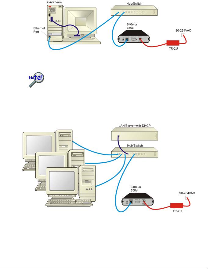
Dedicated Network - making use of a network hub or switch
In this scenario the 640e or 650e connects to the Ethernet through a network hub or switch. At least one computer is also connected to the hub.
Dedicated Network using a Hub/Switch
Some network devices such as a wireless access point may act as a DHCP server. If this is the case, follow the instructions for the LAN with a DHCP server. For detailed information consult the documentation that is specific to your network device.
LAN with a DHCP Server (Local Area Network with a Dynamic Host Configuration Protocol server)
Many corporations use the LAN/Server with DHCP arrangement for their networks. In this type of setup several computers are typically connected to a network that makes use of a DHCP server. In addition, a 640e or 650e is connected to the network hub/switch.
LAN with a DHCP Server
Notes:
¾Using a 640e or 650e on a typical LAN may affect the speed of the network and internet data transfer. Because of this we recommend adding a network card to the computer and using one of the two dedicated network configurations.
¾Contact your network administrator before connecting a 640e or a 650e to a corporate network.
640 & 650 Series |
878893 |
Configuring Ethernet Models 640e & 650e 4-5 |

LAN with no DHCP Server
(Local Area Network with no Dynamic Host Configuration Protocol server)
This scenario looks the same as that shown in the previous illustration, except there is no Dynamic Host Configuration Protocol (DHCP). In this type of setup, one or more computers are connected to a network; and each computer has a static IP address.
STEP 3 – Connect the System Components
What you will need to connect a 640e or a 650e to the Ethernet:
•An available connection to the Ethernet. The connection can be either
-an Ethernet jack on a computer or
-an Ethernet jack on a hub that is connected to the Ethernet.
•An Ethernet patch cable, e.g., a CA-242 (1.5 foot cable) or a CA-242-7 (7-foot cable).
1.Connect the Ethernet cable to the Ethernet jack on the 640e or the 650e.
2.Connect the other end of the Ethernet cable to the Ethernet jack on the host computer or network hub.
STEP 4 – Power-up the System Components
What you will need:
A power supply with a range of 6 to 16 VDC. We recommend the TR-2U power supply.
How to make the connection:
1.Connect the power supply cable, e.g., from the TR-2U, to the External Power connector on the rear panel of the 640e or 650e.
2.Connect the power supply’s plug to a standard AC outlet.
3.If you are using a power supply with a power switch, position it to “ON.”
4.The 640e or 650e Power LED will light up.
4-6 Configuring Ethernet Models 640e & 650e |
878893 |
640 & 650 Series |
STEP 5 - Configure the Computer’s Network Settings [Applies to “dedicated networks” only]
The 640e and 650e Ethernet ports typically require 30 seconds after power-up to configure, before the unit can be accessed via the network.
If using a LAN (Local Area Network), which has a DHCP server, skip this section and continue with STEP 7 - Configure and Test the System using the Daq Configuration Applet (page 4-11).
If using a LAN (Local Area Network), which has no DHCP server, skip this section and continue with STEP 6 - Configure Device Network Settings using DaqIPConfig (page 4-10).
1.Open the Control Panel by navigating from the Windows Desktop as follows:
Start Menu Settings Control Panel.
2.Double-click the “Network and Dial-up Connections” icon.
3.Double-click the “Network Connection” icon for the network that the 640e or 650e is connected to.
Local Area Connection Status
640 & 650 Series |
878893 |
Configuring Ethernet Models 640e & 650e 4-7 |
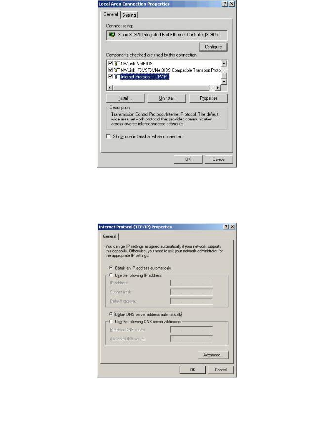
4. In the “Local Area Connection Status” box (previous figure), click on the <Properties> button. The “Local Area Connection Properties” box will appear (following figure).
Local Area Connection Properties
5.Double-click the “Internet Protocol (TCP/IP)” component (previous figure). The “Internet Protocol (TCP/IP) Properties” box will appear (following figure).
Internet Protocol (TCP/IP) Properties
4-8 Configuring Ethernet Models 640e & 650e |
878893 |
640 & 650 Series |
 Loading...