


Instruction Manual
DS-2000 Series
Reflecting and Refracting Telescopes
 Meade Instruments Corporation
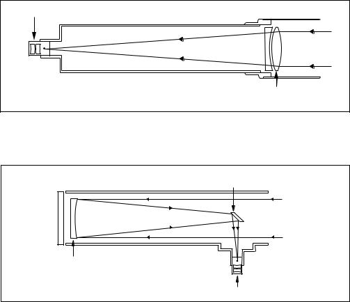
Refracting Telescopes use a large objective lens as their primary light-collecting element. Meade refractors, in all models and apertures, include achromatic (2-element) objective lenses in order to reduce or virtually eliminate the false color (chromatic aberration) that results in the telescopic image when light passes through a lens.
Reflecting Telescopes use a concave primary mirror to collect light and form an image. In the Newtonian type of reflector, light is reflected by a small, flat secondary mirror to the side of the main tube for observation of the image.
Eyepiece |
|
F |
|
|
2-Element |
Refracting Telescope |
Objective Lens |
|
In the refracting telescope, light is collected by a 2-element objective lens and brought to a focus at F.
Secondary
Mirror
Concave |
F |
Mirror |
|
Reflecting Telescope |
Eyepiece |
In contrast, the reflecting telescope uses a concave mirror for this purpose.

WARNING!
Never use a Meade® DS™ Telescope to look at the Sun! Looking at or near the Sun will cause instant and irreversible damage to your eye. Eye damage is often painless, so there is no warning to the observer that damage has occurred until it is too late. Do not point the telescope or its viewfinder at or near the Sun. Do not look through the telescope or its viewfinder as it is moving. Children should always have adult supervision while observing.
CAUTION:
Use care to install batteries as indicated by the battery compartment. Follow battery manufacturer's precautions. Do not install batteries backward or mix new and used batteries. Do not mix battery types. If these precautions are not followed, batteries may explode, catch fire, or leak. Improperly installed batteries void your Meade warranty.
If you are anxious to use your DS Astro Telescope for the first time, before a thorough reading of this instruction manual, see the QUICK-START GUIDE on page 4.
IMPORTANT NOTE:
DS-2000EC users, see APPENDIX E, page 39, for information about your supplied Electronic Controller. Autostar information does not apply.
DS-2000EC users may obtain the #494 Autostar handbox as an optional accessory. See page 40 for more information.
® The name “Meade” and the Meade logo are trademarks registered with the U.S. Patent Office and in principal countries throughout the world. All rights reserved.
© 2001 Meade Instruments Corporation.
CONTENTS |
|
Quick-Start Guide .......................................................... |
4 |
Telescope Features ...................................................... |
7 |
Autostar Features .......................................................... |
9 |
Getting Started .............................................................. |
11 |
Packing List .............................................................. |
11 |
How to Assemble Your Telescope ............................ |
11 |
The Viewfinder .......................................................... |
12 |
Focusing the 5 x 24 Viewfinder .......................... |
12 |
Focusing the 6 x 30 Viewfinder .......................... |
13 |
Aligning the Viewfinder ........................................ |
13 |
Choosing an Eyepiece ............................................ |
14 |
The Barlow Lens ...................................................... |
14 |
Observing ...................................................................... |
15 |
Observing by Moving the Telescope Manually ........ |
15 |
Terrestrial Observing ................................................ |
15 |
Observing Using Autostar's Arrow Keys .................. |
15 |
Slew Speeds ............................................................ |
16 |
Observe the Moon .................................................... |
16 |
Astronomical Observing ............................................ |
16 |
To Track an Object Automatically.............................. |
16 |
Alt/Az Home Position .......................................... |
17 |
Moving Through Autostar’s Menus...................... |
17 |
Initializing Autostar .............................................. |
17 |
Observe a Star Using Automatic Tracking .......... |
18 |
Easy (Two-Star) Align .............................................. |
18 |
Two-Star Alt/Az Alignment ........................................ |
20 |
One-Star Alt/Az Alignment ........................................ |
20 |
Go To Saturn ............................................................ |
20 |
Take a Guided Tour .................................................. |
20 |
Basic Autostar Operation................................................ |
21 |
Autostar Navigation Exercise .................................... |
21 |
Entering Numbers and Text into Autostar ................ |
22 |
Navigating Autostar .................................................. |
22 |
Adjusting the Speed of a Scrolling Message ............ |
22 |
Menus and Menu Options .............................................. |
23 |
Complete Autostar Menu Structure .......................... |
23 |
Object Menu.............................................................. |
23 |
Event Menu .............................................................. |
24 |
Glossary Menu.......................................................... |
25 |
Utilities Menu ............................................................ |
25 |
Setup Menu .............................................................. |
26 |
Optional Accessories ...................................................... |
29 |
Caring for Your Telescope ............................................ |
30 |
Collimation ................................................................ |
30 |
Meade Customer Service ........................................ |
32 |
Specifications ............................................................ |
33 |
Appendix A: Celestial Coordinates ................................ |
35 |
Locating the Celestial Pole ...................................... |
35 |
Appendix B: To Find Objects Not in the Database ........ |
36 |
Appendix C: Observing Satellites .................................. |
37 |
Appendix D: Training the Drive ...................................... |
38 |
Appendix E: Electronic Controller (DS-2000EC Users Only) .. |
39 |
Optional #494 Autostar for DS-2000EC Users ........ |
40 |
Basic Astronomy ............................................................ |
41 |
3
QUICK-START GUIDE
1
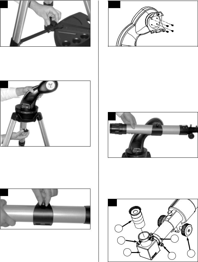
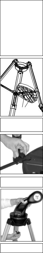
1.Open the tripod: Remove the tripod from the giftbox and stand vertically. Gently pull the legs apart to a fully open position. Turn the center tripod lock knob to secure and stabilize the tripod. Tighten to a firm feel. Caution: Make sure you loosen the tripod lock knob before collapsing the tripod at the end of your viewing session.
2
4 & 5 |
4.Remove 4 screws from the mounting arm shaft: Locate the four screws on the mounting shaft. Remove the screws using a "+" (Phillips head) screwdriver.
5.Attach the cradle to the mounting arm: Line up the cradle with the mounting arm shaft. The cradle contains a molded "key" that fits into a slot on the shaft. Line up the key and the slot, and slide the cradle onto the shaft. This automatically lines up the mating threads on the cradle with the ones on the shaft. Replace the four screws you removed in step #4 into the mating threads as depicted in the diagram above.
6
2.Attach the mounting arm assembly: Place the mounting arm assembly into the tripod base. Reach underneath and thread the mounting knob through the tripod base and into the mounting arm assembly. Tighten to a firm feel only, do not overtighten. While observing, you may wish to slightly loosen this knob and rotate the mounting arm assembly with attached optical tube (see step #6 below) around the horizontal axis.
3
3.Remove the optical tube assembly from the cradle rings: The optical tube assembly is shipped with the cradle rings attached. The rings need to be removed so they can be attached to the mounting arm. Loosen the cradle lock knob until you can open the cradle rings. Remove the optical tube assembly from the cradle rings.
6.Attach and balance the optical tube: Replace the optical tube into the cradle ring. Tighten the cradle rings lock knob so that it holds the optical tube loosely; do not tighten the cradle ring lock knob at this point. Slide the tube back and forth until you find a position where the tube remains horizontal (i.e., without tipping up and down). Tighten the cradle rings lock knob to a firm feel.
7a |
|
D |
|
F |
A |
|
|
|
E |
4
7b |
F |
|
|
|
D |
|
E |
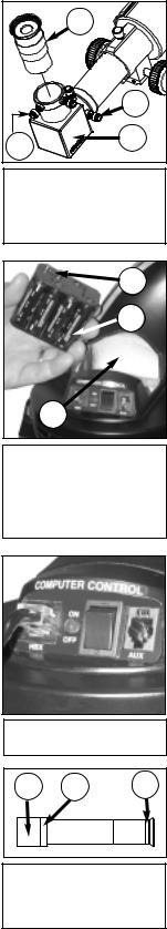
7a. Attach the 90° diagonal prism (refractor models only): Pull out to remove the plastic dust
from the eyepiece holder (A). Slide the tube diagonal prism (B) into the telescope’s eyepieceholder and tighten the thumbscrews (C)
feel only to secure the diagonal prism in
7b. Insert the eyepiece: Remove the supplied eyepiece (D) from its container and place diagonal prism (refractor models only; . 7a) or directly into the eyepiece holder (reflector models only; see Fig. 7b). Tighten the thumbscrew (F) to a firm feel only. Remove
cover from the end of optical tube assembly the focus knobs (E) to bring objects into
8
G
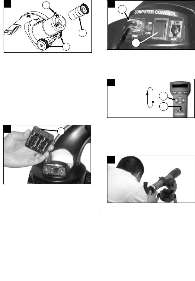
8.Insert batteries: Open the battery compartment by lifting the cover and pulling it away from the drive base.
Remove the battery holder from the compartment and carefully lift the 9v connector out from the compartment. Whenever you replace the batteries, to safeguard the wires, disconnect the 9v connector (G) from the battery holder before removing the batteries.
. Insert eight AA-size batteries into the battery holder, oriented as shown on the diagram on the battery slots of the battery holder. Connect the 9v connector plug to the battery holder. Carefully replace the battery holder back into the battery compartment. Replace the cover.
5
9
I
H
9. Connect Autostar: Be |
that the power |
on the computer |
panel is in the |
. Plug the |
of the Autostar |
Controller into the HBX |
Turn on the com- |
the red LED |
when power is |
supplied to the panel. |
|
|
|
10 |
Slew Speed: |
|
|
|
|
|
Fast |
|
|
|
J |
|
. |
|
|
. |
|
|
. |
K |
|
Slow |
10.Change Speeds: Press the key prompted by Autostar to accept the Sun warning. You can now Arrow keys (J) to move the telescope up, or left. To change one of the tele-
scope's nine slew speeds, briefly press the SPEED/? key (K). Each press decreases the slew
one level, and then will cycle back to speed.
11
|
11. |
the tube: Sight along the side of the |
|
|
telescope's main tube to locate an object. Practice |
|
|
|
|
Autostar Arrow keys to center an object |
|
|
in |
field of view. |
|
|
|
|
|
|
If you |
to attach the viewfinder, see page 12. |
|
|
If you |
to initialize Autostar, see page 17. |
|
|
If you |
to align the telescope, go to page 19. |
|
|
If you |
to use Autostar to automatically view |
|
|
objects, |
to page 20 for some examples. |
|
|
|
|
|

Features of the DS-2000 Series telescopes |
A |
|
|
B |
are virtually identical. Certain features of |
|
|
||
|
|
|
|
|
your telescope may look different than, or |
|
|
|
|
be positioned slightly different than the |
|
|
|
|
one pictured here, but the functionality of |
|
|
|
|
the features is the same. |
|
|
|
|
12 (not visible) |
Fig. 1b (Inset): (A) Dec. Setting |
|||
Circle; (B) Dec. Lock |
|
|||
|
|
|||
|
(on |
|
|
|
|
opposite |
|
|
|
|
side) |
|
|
|
|
25 |
|
|
4 |
14 |
|
|
|
|
|
|
|
|
|
15 |
17 |
|
|
3 |
24 |
|
|
|
|
|
(on bottom |
|
|
|
|
of |
|
|
|
|
not visible) |
|
|
|
27 |
|
|
|
|
21 |
A |
B |
C |
D |
|
Fig. 1c |
Computer Control Panel. (A) |
||
Fig. 1: DS-2000 Series Telescope. |
Handbox |
(B) Power indicator light, (C) |
||
|
ON |
Auxiliary port. |
|
|
6
TELESCOPE FEATURES
An important array of features and manual controls facilitates operation of a DS-2000 telescope. Be sure to become acquainted with all of these controls before attempting observations through the telescope.
Focus Knob - Moves the telescope’s focus drawtube in a finely-controlled motion to achieve precise image focus. Rotate the focus knob clockwise to focus on distant objects, and counterclockwise to focus on nearby objects.
Eyepiece Holder - Holds the eyepiece in place. Also holds the 90° diagonal prism in place (refractor models only).
90° Diagonal Prism (refractor models only) - Holds the eyepiece upright for easy viewing. Results in an upright, but reversed viewing of land objects.
Eyepiece Holder Thumbscrew - Tightens the eyepiece in place. Tighten to a firm feel only.
Eyepiece - Place the supplied eyepiece into the eyepiece holder (reflector models only) or the 90° Diagonal Prism (refractor models only, 3, Fig. 1) and tighten in place with thumbscrew (4, Fig.1).
Focus Lock Knob - Designed to prevent the focuser drawtube from moving when a heavy accessory, such as a camera, is attached to the focuser assembly. For normal observing with an eyepiece and diagonal prism, it is not necessary to use the lock knob.
Viewfinder - Provides an easier way to initially sight objects than the main telescope eyepiece which has a narrower field of view. Slide the eyepiece end of the viewfinder through the front of the viewfinder bracket (Fig. 8a and 8b). See page 11 for more information.
Viewfinder Alignment Screws (4) - Adjust these screws to align the viewfinder. See page 13 for more information.
Viewfinder Alignment Bracket - Attaches the viewfinder to the telescope (Fig. 8a and 8b). See page 11 for more information.
Dec. Setting Circle and Lock
A) Dec. Setting Circle - Displays Declination coordinates (A, Fig. Ib).
B) Dec. Lock - Controls the manual vertical movement of the telescope. Turning the Dec. lock counterclockwise unlocks the telescope enabling it to be freely tilted by hand on the vertical axis. Turning the Dec. lock clockwise (to a firm feel only) prevents the telescope from being moved manually and engages the vertical motor drive clutch for Autostar operation (B, Fig. Ib).
Dew Shield - Reduces dew formation on the telescope's primary lens.
Dust Cap - Pull to remove the dust cap from the front lens of the telescope.
Note: The dust cap should be replaced and the power turned off to the telescope after each observing session. Verify that any dew that might have collected during the observing session has evaporated prior to replacing the dust cap.
Optical Tube - The main optical component that gathers the light from distant objects and brings this light to a focus for observation with the eyepiece.
Cradle Ring Lock Knob - Tighten to a firm feel to hold the optical tube securely in place.
Mounting Arm and Shaft - holds the optical tube assembly. Attaches to the tripod base (23, Fig. 1).
Computer Control Panel (Fig. Ic)
A.Handbox (HBX) Port - Plug the #494 Autostar handbox (AT models) or the Electronic Controller (EC models) into this port.
B.LED - The red power indicator light illuminates when power is supplied to the connected handbox and to the telescope’s motor drive.
C.ON Switch - Turns the Computer Control Panel and Autostar ON or OFF.
Note: Always remove the batteries if they are not to be used for a long period of time.
D.Auxiliary (AUX) Port - Provides connection for current and future Meade accessories. See OPTIONAL ACCESSORIES, page 29.
7
Accessory Tray Attachment Bolts - Attach to wing nuts (not shown) to fasten tray to the tripod. See page 11 for more information.
Note: It is not necessary to remove the tray each time you collapse the tripod. The tray is designed to be collapsed with the legs.
Accessory Tray - Conveniently holds extra eyepieces, Autostar handbox, and other accessories when not in use.
20 Tripod Lock Knob - Tighten to a firm feel to secure tripod legs.
Caution: Loosen the tripod lock knob before collapsing tripod at the end of a viewing session.
21 Tripod Legs Locks (3) - Lift the lock up to loosen inner section of a tripod leg and extend the inner leg to desired height. Press the lock down to lock in place again.
22 Tripod Legs - Spread the legs out as far as they will open for a secure viewing platform.
23 Tripod Base - Holds the mounting arm assembly (16, Fig. 1) in place.
24 Right Ascension (R.A.) Setting Circle - Displays Right Ascension coordinates.
25 Battery Compartment - Install eight user-supplied AA batteries in this compartment. See page 12 for more information.
26 Base Lock Knob (not visible in photo) - Attaches mounting arm assembly to tripod base. Loosen before moving the optical tube on the horizontal axis. See page 11 for more information.
27 Inner Support Struts (3) - Make the tripod more secure and stable.
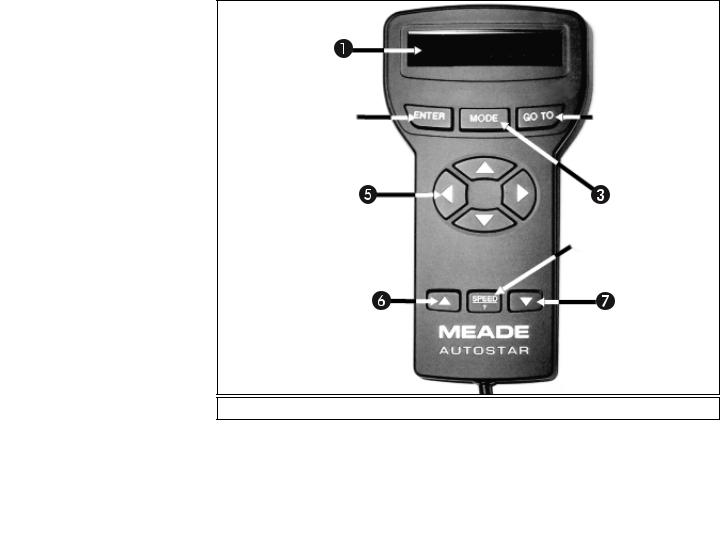
Fig. 2: #494 Autostar Handbox.
8
NOTE: DS-2000EC users, see APPENDIX E,
page 39, for information about your supplied Electronic Controller. Autostar information does not apply.
DS-2000EC users may obtain the #494 Autostar handbox as an optional accessory. See page 40 for more information.
AUTOSTAR FEATURES
Control of the DS-2000AT Series Telescopes is through the operation of the #494 Autostar handbox. Nearly all functions of the telescope are accomplished with just a few pushes of Autostar’s buttons. Some of the major features of Autostar are:
■Automatically move the telescope to any of the 1400 objects stored in the database or manually enter the astronomical coordinates of any celestial object.
■Take a guided tour of the best celestial objects to view on any given night of the year.
■Access a glossary of astronomical terms.
■Calculate which eyepiece to use for optimum viewing of a celestial object.
The Autostar Computer Controller provides control of virtually every telescope function within a compact handbox. Autostar has soft-touch keys designed to have a positive feel. The LCD (Liquid Crystal Display) is backlit with a red LED (Light Emitting Diode) for easy viewing in the dark. The backlit display, key arrangement, and sequential database make Autostar extremely user friendly.
NOTE: Autostar does not require batteries; the telescope’s batteries supply power to Autostar.
2-Line LCD Display - Provides an interface between Autostar and the telescope.
•Top line: Lists the primary category or menu item.
•Bottom line: Contains a menu option or information about an object or subject, depending on which function is being performed.
ENTER Key - Accesses, in a sequential manner, the next menu or data level in the Autostar database. See MOVING THROUGH AUTOSTAR'S MENUS, page 17 and MENUS AND MENU OPTIONS, page 23.
NOTE: If ENTER is pressed for two seconds or more and then released, Autostar emits a beep and “ENTER to Sync”
is displayed. "ENTER to Sync" is relevant only after the telescope has
been aligned and is pointing at an object. If the "ENTER to Sync" fea-
ture is accessed by mistake, press MODE to return to the previous screen. See HIGH PRECISION, page 27, for more details about this feature.
MODE Key - Returns to the previous menu or data level in the Autostar database until the top level, “Select Item," is reached. The MODE key is similar to the ESCAPE key on a computer.
NOTE: Pressing MODE while in the “Select Item” level moves Autostar to the topmost screen: “Select Item: Object.”
NOTE: If MODE is pressed and held for two seconds or more, the following information is then available using the Scroll keys (6 and 7, Fig. 2):
• Right Ascension and Declination (astronomical) coordinates (see
APPENDIX A, page 35.)
9
DEFINITION:
Throughout this manual, you will notice the term "Alt/Az." Alt/Az is frequently used to refer to Altitude (vertical) and Azimuth (horizontal). Alt/Az is just one of many methods used by amateur astronomers to help locate stars in the night sky.
Fasten |
wingnuts |
Fig. 3 Attach Tray to the tripod: Thread the wingnuts to the bolts (bottom view).
Fig. 4: Secure the tripod: turn the tripod lock knob.
Fig. 5: Attach the mounting arm to the tripod base.
•Altitude (vertical) and Azimuth (horizontal) coordinates
•Local Time and Local Sidereal Time (LST)
•Timer and Alarm Status
Press MODE again to return to the previous menu.
GO TO Key - Slews (moves) the telescope to the coordinates of the currently selected object. While the telescope is slewing, the operation may be aborted at any time by pressing any key except GO TO. Pressing GO TO again resumes the slew to the object.
The GO TO key also allows you to perform a "spiral search." A spiral search is useful when the telescope slews to an object, but that object is not visible in the eyepiece after the telescope finishes its search. (This sometimes occurs during the alignment procedure.) Press GO TO when the slew is finished and the telescope starts slewing in a spiral pattern at a very slow speed around the search area. Look through the eyepiece and when the object does become visible, press MODE to stop the spiral search. Then use the Arrow keys to center the object.
Arrow Keys - Move the telescope in a specific direction (up, down, left, and right), at any one of nine different speeds. Speed selection is explained in SLEW SPEEDS, page 16. The following functions are also available with the Arrow keys:
•Data Entry - Use the Up and Down Arrow keys to scroll through the letters of the alphabet and numerical digits. The Down Arrow key starts with the letter "A" and the Up Arrow key starts with the digit "9." The Left and Right Arrow keys are used to move the blinking cursor left and right across the LCD display.
•Alt/Az Alignment - Use the Up and Down Arrow keys to move the telescope ver-
tically up and down. The Left Arrow key rotates the telescope horizontally counterclockwise, while the Right Arrow key rotates it clockwise.
Tip: When a message is scrolling across the display, press and hold the Up Arrow key to increase the scrolling speed or press and hold the Down Arrow key to decrease the scrolling speed.
, Scroll Keys - Access database options within a selected menu. The menu is displayed on the top line of the screen. Options within the menu are displayed, one at a time, on the second line. Press the Scroll keys to move through the options. Press and hold a Scroll key to move quickly through the options.
The Scroll keys also scroll through the letters of the alphabet and numerical digits.
NOTE: The Scroll Down key and the Down Arrow key move forward through the alphabet & digits (A to Z, 0 to 9). The Scroll Up key and the Up Arrow key move backward (Z to A, 9 to 0). Common symbols are also available in the list.
Speed/? Key - Pressing the Speed/? key cycles through the nine slew speeds that move the telescope. Each time the Speed/? key is pressed briefly, the current slew speed is shown for about two seconds on the display. See SLEW SPEEDS, page 16.
The Speed/? key also accesses the "Help" file. "Help" provides on-screen information on how to accomplish whatever task is currently active.
NOTE: Pressing the Speed/? key very briefly changes the slew speed. Holding down the Speed/? key longer (one to two seconds) accesses the Help function.
If you have a question about an Autostar operation, e.g., INITIALIZATION, ALIGNMENT, etc., hold down the Speed/? key and follow the directions that scroll on the second line of the LCD screen. When a word appears in [brackets], press ENTER to access the Autostar Glossary. A definition or more detailed information is displayed. Press MODE to return to the scrolling Autostar Help display.
When satisfied with the Help provided, press MODE to return to the original screen and continue with the chosen procedure.
Coil Cord (not shown) - Plug the Autostar coil cord into the HBX port (A, Fig. 1c) of the computer control panel of the telescope.
10
Fig. 6: Attach cradle to mounting arm.
Fig. 8b: Attach the viewfinder bracket to the reflector optical tube assembly.
GETTING STARTED
Packing List
Getting the telescope ready for first observations requires only a few minutes. When first opening the packing box, note carefully the parts listed on your packing list or giftbox.
How to Assemble Your Telescope
The telescope attaches directly to the tripod. The telescope in this way is mounted in an “Altazimuth” (“Altitude-Azimuth,” or “vertical-horizontal”) format. The telescope in this configuration moves along the vertical and horizontal axes, corresponding respectively to the Declination (vertical) and Right Ascension (horizontal) axes in the astronomical observing mode.
1.Open the tripod: After removing the field tripod from its shipping carton, stand the tripod vertically, with the tripod feet down and with the tripod still fully collapsed. Gently pull the legs apart to a fully open position.
2.Attach the tray to the tripod: Place the tray (19, Fig. 1) over the inner support strut that contains two bolt holes. Line up the bolts holes on the tray with the bolt holes on the strut. Slide the two included bolts through the top of bolt holes (18, Fig. 1) and tighten the bolts with the included wing nuts on the bottom side of the tray (Fig. 3). Tighten to a firm feel only.
Note: The tray does not have to be removed when you collapse the tripod at the end of a viewing session.
3.Secure the tripod: Turn the center tripod lock knob (Fig. 4) to help stabilize and secure the tripod.
Caution: Make sure that you loosen the tripod lock knob before collapsing the tripod.
4.Attach the mounting arm assembly to the tripod base: First note the three pads in the tripod base (23, Fig. 1) and three pads on the mounting arm assembly (16, Fig. 1). These pads allow the mounting arm assembly to move more easily inside the base.
Place the mounting arm assembly into the tripod base and continue to hold onto the arm assembly. With your other hand, reach underneath the base and thread the mounting lock knob (26, Fig. 1) through the tripod base and into the mounting arm assembly. Tighten to a firm feel only; do not overtighten. While observing, you may wish to loosen this knob and rotate the mounting arm assembly and optical tube (see step #8) on the horizontal axis.
5.Remove the optical tube assembly from the cradle rings: The optical tube assembly is shipped with the cradle rings attached. The rings need to be removed before they can be attached to the mounting arm. Loosen the cradle lock knob (14, Fig. 1) until you can open the cradle rings. Remove the optical tube assembly (13, Fig. 1) from the cradle rings.
6.Remove 4 screws from the mounting arm shaft: Locate the four screws on the mounting shaft. Remove the screws using a "+" (Phillips head) screwdriver. Set the screws aside.
7.Attach the cradle to the mounting arm: Line up the cradle with the mounting arm shaft. The cradle contains a molded "key" that fits into a slot on the shaft. Line up the key and the slot, and slide the cradle onto the shaft. This automatically lines up the mating threads on the cradle with the ones on the shaft. Replace the four screws into the mating threads using the Phillips head screwdriver (Fig. 6). The key and slot on the shaft set limit stops for the telescope so that it doesn't strike the base or pass beyond approximately 90° upright when you use the Autostar handbox.
8.Attach and balance the optical tube: Replace the optical tube into the cradle ring. Tighten the cradle ring lock knob so that it holds the optical tube loosely; do not tighten the cradle ring lock knob at this point. Slide the tube back and forth until you find a position where the tube remains horizontal (i.e., without slightly tipping up or down). Tighten the cradle rings lock knob to a firm feel. See Fig. 7. Adjust the length of the tripod legs to a comfortable viewing height using the leg locks (21, Fig. 1).
9.Attach the viewfinder bracket: Attach the bracket to the optical tube as shown in Fig 8a (the refractor viewfinder) or 8b (the reflector viewfinder). Using a Phillips head screwdriver, thread the two attachment screws in the bracket (these screws are placed inside the bracket at the factory) into the mating threads located on the optical tube.
11
Fig. 7: Attach and bal-
Fig.8a:Attach the
3 |
2 |
4 |
Fig. 9: Attach the 90° (1), tighten prism screws (2), insert the piece (3), tighten thumbscrews (4).
1
Fig. 10: Insert eight batteries inside the compartment:
(1)Battery
(2)Battery holder
(3)9v connector
10.Attach the viewfinder: Carefully remove the rubber eyecup from the viewfinder before sliding the viewfinder into the bracket. Slide the viewfinder, eyepiece-end first, into the viewfinder bracket (see Figs. 8a and 8b). Replace the rubber eyecup after the viewfinder is positioned in the bracket. Tighten the four alignment thumbscrews (8, Fig. 1) to a firmfeel to hold the viewfinder in the bracket.
11.Attach the 90° diagonal prism (refractor models only): Pull out to remove the plastic dust cover from the eyepiece holder. Slide the tube of the diagonal prism (3, Fig. 1) into the telescope’s eyepiece-holder (2, Fig. 1) and tighten the thumbscrews (to a firm feel only) to secure the diagonal prism in place.
12:Insert the eyepiece: Remove the supplied eyepiece (5, Fig. 1) from its container and place it in the diagonal prism (refractor models only; 3, Fig. 1) or directly into the eyepiece holder (2, Fig. 1) (reflector models only). Tighten the thumbscrew (2, Fig. 1) to a firm feel only.
13.Insert batteries: The telescope’s battery compartment (1, Fig. 10) is located on top of the drive base. Open the battery compartment by lifting the cover and pulling it away from the drive base.
|
Remove the battery holder from the compartment and carefully lift the 9v connector out |
|
from the compartment. Take care not to accidentally detach the wires of the battery con- |
|
nector from the base. Whenever you replace the batteries, to safeguard the wires, discon- |
|
nect the 9v connector from the battery holder before removing the batteries. |
. |
Insert eight AA-size batteries into the battery holder, oriented as shown on the diagram on |
|
the battery slots of the battery holder. Connect the 9v connector plug to the battery holder. |
|
Carefully replace the battery holder back into the battery compartment. Replace the cover. |
CAUTION: Use care to install batteries as indicated by the battery compartment. Follow battery manufacturer's precautions. Do not install batteries backwards or mix new and used batteries. Do not mix battery types. If these precautions are not followed, batteries may explode, catch fire, or leak. Improperly installed batteries void your Meade warranty. Always remove the batteries if they are not to be used for a long period of time.
14.Connect Autostar: Be certain that the power switch on the computer control panel (C, Fig. 1c) is in the OFF position. Plug the coil cord of the Autostar Controller into the HBX port (A, Fig. 1c). Turn on the power switch; the red LED lights when power is supplied to the panel.
NOTE: Autostar does not require batteries; the telescope’s batteries supply power to Autostar.
Fig. 11: Connect the HBX port.
3 |
2 |
15.Remove the dust cover: Pull out the dust cover (12, Fig. 1) from the optical tube assembly (13, Fig. 1).
Assembly of the basic telescope is now complete.
The Viewfinder
Because the main telescope has a fairly narrow field of view, locating objects directly in the main telescope can sometimes be difficult. The viewfinder (7, Fig. 1) is a small, wide-field telescope with crosshairs that permits you to more easily locate objects. When the viewfinder and optical tube are aligned to each other, both point to the same position in the sky. An object located in the viewfinder is therefore also positioned within the field of the main telescope. Before aligning the viewfinder to the optical tube, focus the viewfinder.
Focusing the Viewfinder: Each Meade DS-2000 telescope is supplied with one of two viewfinder models, 5 x 24mm or a larger 6 x 30mm. Identify the viewfinder size from the gift box cover or the packing slip supplied with your telescope.
Fig. 12: 6 x 30mm Viewfinder:
(1)Eyepiece
(2)Focus cell
(3)Focus lock ring
Focusing the 5 x 24mm Viewfinder:
1.Turn the viewfinder eyepiece on its internal thread. Generally a few turns are sufficient to achieve proper focus.
12
NEVER point the telescope directly at
or near the Sun at any time! Observing the Sun, even for the smallest fraction of a second, will result in instant and irreversible eye damage, as well as physical damage to the telescope itself.
Telescope
Viewfinder Eyepiece
A.Not aligned
B. Aligned
Fig. 13: Aligning the viewfinder. Note that objects appear upside-down and reversed left-for-right when observed in the viewfinder.
Focusing the 6 x 30mm Viewfinder:
The 6 x 30mm viewfinder is locked into permanent focus at infinity. Look through the viewfinder at a distant land object. If the focus is not sharp, follow this procedure:
1.Loosen the focus lock ring (3, Fig. 12) a few turns, permitting the lens cell (2, Fig. 12) to be rotated.
2.Look through the viewfinder eyepiece (1, Fig. 12) at a distant land object and rotate the lens cell until the object is sharply focused.
3.Tighten the focus lock ring (3, Fig. 12) up against the lens cell.
Important Note: Objects appear upside-down and reversed left-for-right when observed in the viewfinder. With the refracting telescope models, objects viewed through the main telescope with the diagonal mirror (3, Fig. 1) in place appear right- side-up, but reversed left-for-right. This image inversion is of no consequence when observing astronomical objects, and in fact all astronomical telescopes yield inverted images. During terrestrial observing, where a fully-correctly-oriented image (right-side up and correct left-for-right) is desirable, an optional Meade 45° Erecting Prism (available in either 0.965" or 1.25" format to suit the appropriate Meade telescope model) is available. See the "Optional Accessories," page 29, or consult the Meade Telescope Catalog.
Note that for reflecting telescope models, no means of image inversion is available; while these telescopes may be used for terrestrial observing, the image will not be correctly oriented in either right-side-
up or left-for-right orientations.
Aligning the Viewfinder:
It is recommended that you perform steps 1 through 4 of this procedure during the daytime and step 5 at night.
1.Loosen the tripod base lock knob (26, Fig. 1) and the Dec. lock (10, Fig. 1), by turning the lock about one turn counterclockwise, permitting the telescope to move freely on its axes.
2.If you have not already done so, place a low-power (e.g., 25mm) eyepiece in the diagonal prism of the main telescope (3, Fig. 1) and point the telescope at an easy-to-find land object (e.g., the top of a telephone pole). Turn the focuser knob (1, Fig. 1) so that the image is sharply focused. Center the object precisely in the main telescope’s field of view.
3.Re-tighten the tripod base lock knob (26, Fig. 1) and the Dec. lock (10, Fig. 1).
4.Then, looking through the viewfinder, turn some or all of the viewfinder’s alignment screws (8, Fig. 1) until the viewfinder’s crosshairs point precisely at the same object as centered in the main telescope. The viewfinder is now aligned to the main telescope. The right-hand image in Fig. 13A shows an object centered in the main telescope before the viewfinder (the left-hand
DS-2000 TIPS
Too Much Power?
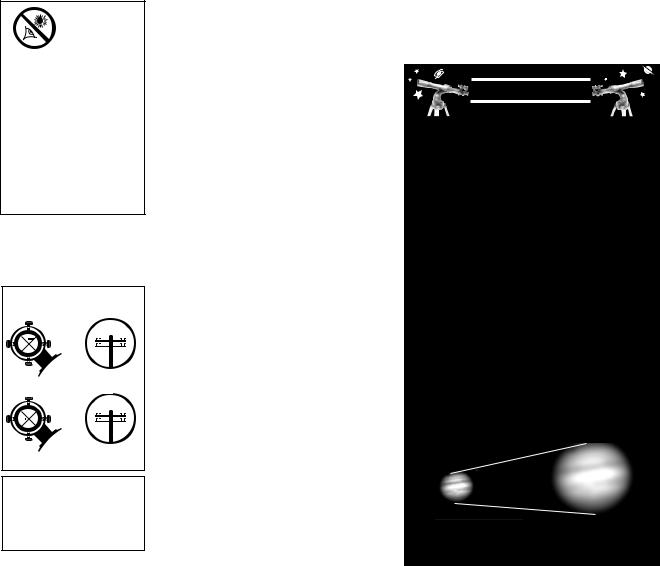
Can you ever have too much power? If the type of power you’re referring to is eyepiece magnification, yes, you can! The most common mistake of the beginning observer is to “overpower” a telescope by using high magnifications which the telescope’s aperture and atmospheric conditions cannot reasonably support. Keep in mind that a smaller, but bright and well-resolved image is far superior to one that is larger, but dim and poorly resolved (see below). Powers above 200X should be employed only under the steadiest atmospheric conditions.
Autostar can calculate the best eyepiece for you to use. Try out the “Eyepiece Calc” feature in the Utilities menu.
Most observers should have three or four additional eyepieces to achieve the full range of reasonable magnifications possible with the DS-2000 telescopes. See “OPTIONAL ACCESSORIES,” page 29.
Fig. 14a & 14b: Jupiter; example of too much magnification.
13
Fig. 15: 25mm and 9mm eyepieces.
DEFINITION:
A capital "X" is used to denote an eyepiece's (or a Barlow's) power or magnification. For example, "40X" is read as "40-power."
image) has been aligned to the main telescope. Fig. 13B shows these same images after the viewfinder and main telescope are aligned.
5.Check this alignment on a celestial object, such as the Moon or a bright star, and make any necessary refinements.
Choosing an Eyepiece
A telescope’s eyepiece magnifies the image formed by the telescope’s main optics. Each eyepiece has a focal length, expressed in millimeters, or “mm.” The smaller the focal length, the higher the magnification. For example, an eyepiece with a focal length of 9mm has a higher magnification than an eyepiece with a focal length of 25mm.
Your telescope comes supplied with a low-powered 25mm eyepiece which gives a wide, comfortable field of view with high image resolution.
Low power eyepieces offer a wide field of view, bright, high-contrast images, and eye relief during long observing sessions. To find an object with a telescope, always start with a lower power eyepiece such as a 25mm. When the object is located and centered in the eyepiece, you may wish to switch to a higher power eyepiece to enlarge the image as much as practical for prevailing seeing conditions.
NOTE: Viewing conditions vary widely from night-to-night and site-to-site. Turbulence in the air, even on an apparently clear night, can distort images. If an image appears fuzzy and ill-defined, back off to a lower power eyepiece for a more well-resolved image.
The power, or magnification of a telescope is determined by the focal length of the telescope and the focal length of the eyepiece being used. To calculate eyepiece power, divide the telescope's focal length by the eyepiece's focal length. For example, you may wish to use a 25mm eyepiece with the DS-2000 model DS-2114S. Look up the focal length of the DS-2114S under "Specifications: DS-2114S," page 33. The focal length is listed as 1000mm.
Telescope focal length divided by Eyepiece focal length = Eyepiece power
1000 25 = 40
The eyepiece power, or magnification is therefore 40X (approximately).
The Barlow Lens
Some Meade telescopes include a power multiplier called a Barlow lens. Consisting of a lens mounted in a 4"-long (10cm) tube, the Barlow doubles or triples the power obtained when an eyepiece is used alone. In the example above, a 25mm eyepiece results in 40X magnification with the DS-2114S telescope; when this same eyepiece is used in conjunction with a 2x Barlow lens, power is doubled to 80X. To use the Barlow, insert it into the diagonal prism (refractor models only) or eyepiece holder, followed by the eyepiece.
14
 Loading...