

McIntosh MS-750 Owners manual
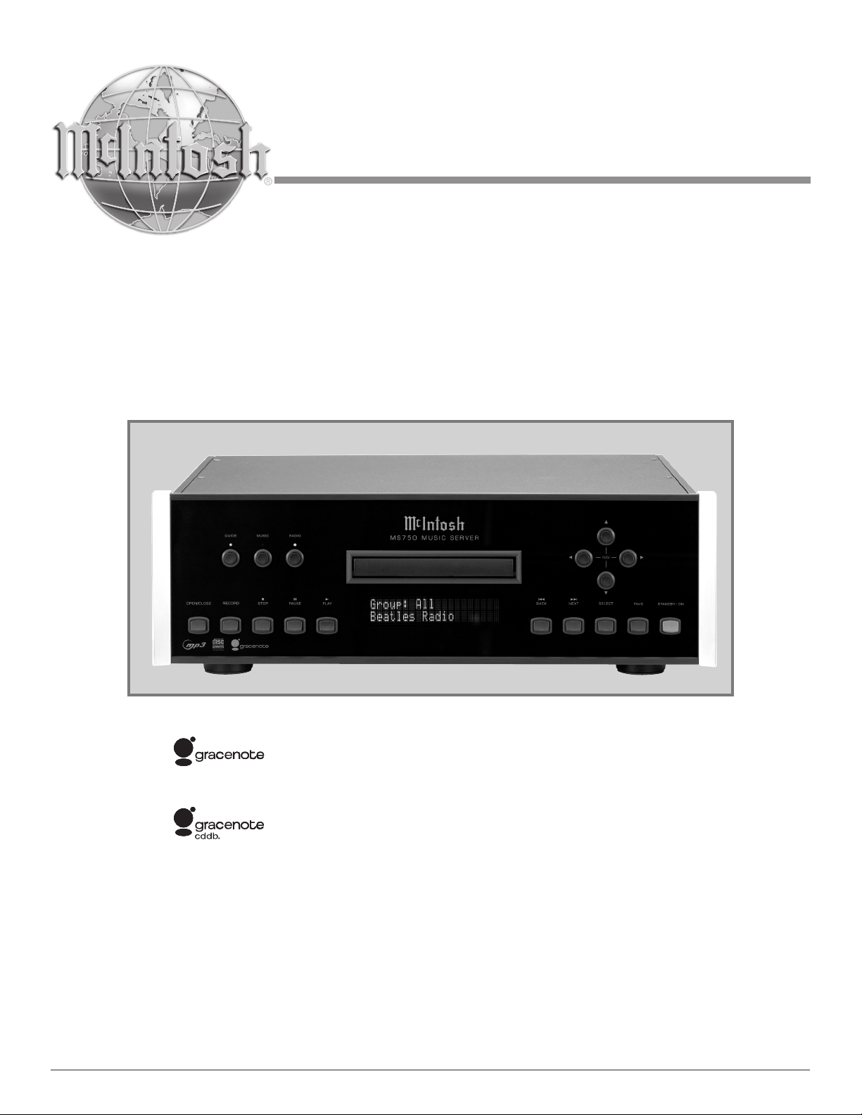
Music Server
TM
Gracenote CDDB® Client Software, copyright 2000-2006 Gracenote. This product and service
may practice one or more of the following U.S. Patents: #5,987,525; #6,061,680; #6,154,773,
#6,161,132, #6,230,192, #6,230,207, #6,240,459, #6,330,593, and other patents issued or
pending.
Gracenote and CDDB are registered trademarks of Gracenote. The Gracenote logo and
logotype, and the “Powered by Gracenote” logo are trademarks of Gracenote.
MS750
Owner’s Manual
McIntosh Laboratory, Inc. 2 Chambers Street Binghamton, New York 13903-2699 Phone: 607-723-3512 FAX: 607-724-0549

The lightning flash with arrowhead,
within an equilateral triangle, is
intended to alert the user to the
presence of uninsulated “dangerous voltage” within the product’s
enclosure that may be of sufficient
magnitude to constitute a risk of
electric shock to persons.
The exclamation point within an
equilateral triangle is intended to
alert the user to the presence of important operating and maintenance
(servicing) instructions in the literature accompanying the appliance.
WARNING - TO REDUCE RISK OF
FIRE OR ELECTRICAL SHOCK, DO
NOT EXPOSE THIS EQUIPMENT TO
RAIN OR MOISTURE.
CAUTION -
Invisible Laser Radiation when open. DO
NOT stare into the beam or view directly
with optical instruments. Use of controls
or adjustments or performance of proce
dures other than those specified in the
Owners Manual may result in Hazardous
Radiation Exposure.
LUOKAN 1 LASERLAITE
KLASS 1 LASER APPARAT
NO USER-SERVICEABLE PARTS
INSIDE. REFER SERVICING TO
QUALIFIED PERSONNEL.
To prevent the risk of electric shock, do not remove cover or
back. No user-serviceable parts inside.
-
VAROITUS!
VARNING!
This product incorporates an embedded
2
Laitteen kayttaminen muulla kuin
tassa kayttoohjeessa mainitulla
tavalla saattaa altistaa kayttajan
turvallisuusluokan 1 ylittavalle
nakymattomalle lasersateiiylle.
Om apparaten anvands pa annat satt
an i denna bruksanvisning specifi
cerats, kan anvandaren utsattas for
osynbg laserstraining, som overskrider
gransen for laserklass 1.
CLASS 3B Laser (IEC60825-1).
-

IMPORTANT SAFETY
INSTRUCTIONS!
PLEASE READ THEM BEFORE
OPERATING THIS EQUIPMENT.
1. Read these instructions.
2. Keep these instructions.
3. Heed all warnings.
4. Follow all instructions.
5. Do not use this apparatus near water.
6. Clean only with a dry cloth.
7. Do not block any ventilation openings. Install in
accordance with the manufacturer’s instructions.
8. Do not install near any heat sources such as radiators, heat registers, stoves, or other apparatus
(including amplifiers) that produce heat.
9. Do not defeat the safety purpose of the polarized
or grounding-type plug. A polarized plug has two
blades with one wider than the other. A grounding type plug has two blades and a third grounding prong. The wide blade or the third prong are
provided for your safety. If the provided plug does
not fit into your outlet, consult an electrician for
replacement of the obsolete outlet.
10. Protect the power cord from being walked on or
pinched particularly at plugs, convenience receptacles, and the point where they exit from the
apparatus.
11. Only use attachments/accessories specified by the
manufacturer.
12. Use only with the cart, stand, tripod, bracket, or
table specified by the manufacturer,
or sold with the apparatus. When a
cart is used, use caution when moving the cart/apparatus combination
to avoid injury from tip-over.
13. Unplug this apparatus during lightning storms or
when unused for long periods of time.
14. Refer all servicing to qualified service personnel. Servicing is required when the apparatus has
been damaged in any way, such as power-supply
cord or plug is damaged, liquid has been spilled or
objects have fallen into the apparatus, the apparatus has been exposed to rain or moisture, does not
operate normally, or has been dropped.
15. Do not expose this equipment to dripping or
splashing and ensure that no objects filled with liquids, such as vases, are placed on the equipment.
16. To completely disconnect this equipment from the
a.c. mains, disconnect the power supply cord plug
from the a.c. receptacle.
17. The mains plug of the power supply cord shall
remain readily operable.
18. Do not expose batteries to excessive heat such as
sunshine, fire or the like.
3

Thank You
Table of Contents
Your decision to own this McIntosh MS750 Music Server
ranks you at the very top among discriminating music lis
teners. You now have “The Best.” The McIntosh dedication
to “Quality,” is assurance that you will receive many years
of musical enjoyment from this unit.
Please take a short time to read the information in this
manual. We want you to be as familiar as possible with all
the features and functions of your new McIntosh.
-
Please Take A Moment
The serial number, purchase date and McIntosh Dealer
name are important to you for possible insurance claim or
future service. The spaces below have been provided for
you to record that information:
Serial Number: __________________________________
Purchase Date: __________________________________
Dealer Name: ___________________________________
Technical Assistance
If at any time you have questions about your McIntosh
product, contact your McIntosh Dealer who is familiar
with your McIntosh equipment and any other brands that
may be part of your system. If you or your Dealer wish
additional help concerning a suspected problem, you can
receive technical assistance for all McIntosh products at:
McIntosh Laboratory, Inc.
2 Chambers Street
Binghamton, New York 13903
Toll Free: 866-458-6910 (9:00am - 6:00pm EST, M-F)
Phone:607-723-3512 (8:30am - 5:00pm EST, M-F)
Fax: 607-724-0549
Customer Service
If it is determined that your McIntosh product is in need of
repair, you can return it to your Dealer. You can also return
it to the McIntosh Laboratory Service Department. For
assistance on factory repair return procedure, contact the
McIntosh Service Department at:
Safety Instructions ............................................................
Thank You and Please Take a Moment .............................
Technical Assistance and Customer Service .................... 4
Table of Contents ..............................................................4
Connector and Cable Information ....................................5
Important Information ......................................................6
Introduction .......................................................................
Performance Features .......................................................7
Dimensions .......................................................................8
Installation ........................................................................ 9
Connections:
Rear Panel Connections .................................................. 10
How to Connect the MS750 ............................................ 11
Front Panel Features:
Front Panel Indicators and Push-buttons ........................12
Remote Control:
Remote Control Push-buttons ......................................... 14
How to Operate by Remote Control ...............................15
Setup:
How to Operate the Setup Mode ....................................16
Getting Disc Information ........................................... 16-17
User Preferences ........................................................ 17-18
Other Modes ...................................................................18
Setting Your Time Zone .................................................18
Password Protection ........................................................ 19
Ethernet Settings .............................................................19
Server Settings and MS750 Music Sharing ....................20
Selecting the Audio Encoder Type .................................20
Setting the Disc Insert Preferences ................................. 21
Video Adjustments .....................................................21-23
Using a Touch Panel .................................................. 23-24
IR Remote Control ..........................................................24
Direct Access Codes .......................................................24
Play List Hot Push-buttons .............................................24
Serial COM Ports ............................................................25
MS750 Utilities ...............................................................25
Restarting the System .....................................................25
Updating the Software ....................................................26
2
4
7
McIntosh Laboratory, Inc.
2 Chambers Street
Binghamton, New York 13903
Phone: 607-723-3515
Fax: 607-723-1917
Copyright 2007 © by McIntosh Laboratory, Inc.
4
Operation:
Getting Music Into the MS750 ................................... 28-31
Erasing a CD-RW Disc ................................................... 31
Browsing your Music Library .................................... 31-32
Changing Guide Views ..............................................32-33
Jukebox Play Modes ..................................................33-35
Connector and Cable Information
Power
Control
Ground
N/C
Data
Signal
N/C
Data
Ground
IR Data
Control
Ground
+12V
Pin 1
Pin 8
Pin 1
Pin 8
Table of Contents, con’t
Creating Play Lists ..........................................................35
Creating Groups ..............................................................36
Internet Radio Stations ...................................................36
Adding Internet Radio Stations ......................................37
Updating the Internet Radio Station List ........................37
Editing Music Information .............................................37
Editing Track Names ......................................................38
Searching and Selecting Covers ...............................38-39
Editing Radio Info, Play Lists and Groups ............... 39-40
Deleting Music, Play Lists, and Groups .........................41
Creating CDs and a Custom Mix CD .............................42
Duplicating a CD ............................................................42
Recording from an External Source ...............................43
Controlling the MS750 from a Web Browser .................43
Setting up the MS750 Web Server ..................................43
Using the Web User Interface and Music Client ............44
MS750 Backup and Restore ...................................... 44-45
ID3 Tag Support ..............................................................45
Troubleshooting ..............................................................45
Additional Information:
Specifications .................................................................. 50
Packing Instruction .........................................................51
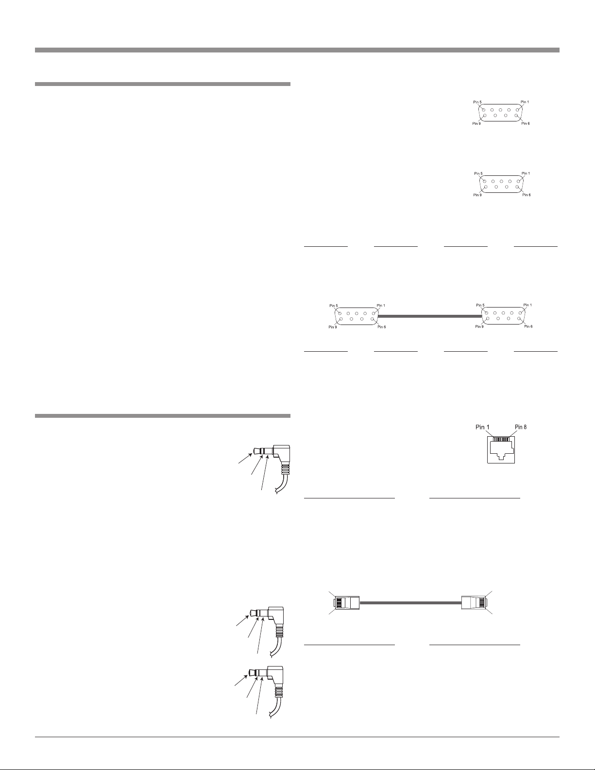
Connector and Cable Information
Power Control Connector
The MS750 Power Control Input Jack receives Power
On/Off Signals when connected to other
McIntosh Components. A 1/8 inch stereo
mini phone plug is used for connection to
the Power Control Input on the MS750.
Note: The Data ad Power Control Connect-
ing Cable is available from the McIntosh Parts Department:
Data and Power Control Cable Part No. 170-202
Six foot, shielded 2 conductor, with 1/8 inch stereo mini
phone plugs on each end.
Data and IR Input Port Connectors
The MS750 Data In Port receives Remote Control Signals.
A 1/8 inch stereo mini phone plug is
used for connection.
The IR IN Port also use a 1/8 inch
stereo mini phone plug and allows the
connection of other brand IR Receivers
to the MS750. It also provides +12 Volts
to power the external sensor.
Communication Ports 1-3 (RS232 Connector Pin Out)
1. Carrier Detect 6. Data Set Ready
2. Receive Data 7. Request to Send
3. Transmit Data 8. Clear to Send
4. Data Terminal 9. Ring Indicator
5. System Ground
Communication Port 4 (RS232 Connector Pin Out)
1. Carrier Detect 6. Data Set Ready
2. Transmit Data 7. Request to Send
3. Receive Data 8. Clear to Send
4. Data Terminal 9. Ring Indicator
5. System Ground
RS232 Cable - Straight Thru Connections
Pin Number
1 → 1 6 → 6
2 → 2 7 → 7
3 → 3 8 → 8
4 → 4 9 → 9
5 → 5
RS232 Cable - Null Modem Connections
Pin Number Pin Number Pin Number Pin Number
1 → 1 6 → 4
2 → 3 7 → 8
3 → 2 8 → 7
4 → 6 9 → 9
5 → 5
Ethernet RJ45 Socket
1. Tranceive Data (+) 5. N/C
2. Tranceive Data (-) 6. Receive Data (-)
3. Receive Data (+) 7. N/C
4. N/C 8. N/C
Ethernet Cable - Straight Thru Connections
Pin Number - Wire Color
1. Orange/White → 1. Orange/White
2. Orange → 2. Orange
3. Green/White → 3. Green/White
4. Blue → 4. Blue
5. Blue/White → 5. Blue/White
6. Green → 6. Green
7. Brown/White → 7. Brown/White
8. Brown → 8. Brown
Ethernet Cable - Crossover Connections
Pin Number - Wire Color
1. Orange/White → 1. Green/White
2. Orange → 2. Green
3. Green/White → 3. Orange/White
4. Blue → 4. Blue
5. Blue/White → 5. Blue/White
6. Green → 6. Orange
7. Brown/White → 7. Brown/White
8. Brown → 8. Brown
Pin Number Pin Number Pin Number
Pin Number - Wire Color
Pin Number - Wire Color
5
Important Information
1. For additional connection information, refer to the
owner’s manual(s) for any component(s) connected to
the MS750 Music Server.
2. The MS750 Music Server will play all standard CD
Audio Discs that conform to the Official Compact Disc
Standards which is indicated by the Symbol .
3. The MS750 requires Connection to the Internet for the
MS750 to be registered and authenticated. The built-in
Gracenote Program also requires the Internet for looking up the Album Title, Track Name, and Track Playing
Time of the music and display it.
4. The MS750 IR IN jack is configured for non-McIntosh
IR sensors such as Xantech Model 291-80 or other compatible sensor.
5. When connecting external CD Changers to the MS750
there are two possible communication connection types,
S-Link and RS232 Com Port. These connections allow
the MS750 to control the changers. Refer to the Owner’s
Manual supplied with the changer to determine which
connection type(s) and the correct cable types to use.
At the time of the printing of this Owner’s Manual the
Sony DVP-CX777ES changer is known to be compatible with the MS750.
6. The MS750 may be controlled by an external Touch
Screen Panel from the following companies:
• AMX • Net Streams
• Crestron • Opus
• Elan Via • Phillips Pronto
• Home Theater Master • RTI
• Lexicon • Sonance
• Marantz • Xantech
7. The Ethernet Connector on the MS750 allows for con-
nection to a computer network for accessing the Internet and adding a second MS750 to the Audio/Video
System.
If there is no computer network available, an external
modem may be connected to the MS750 for access
to the Internet. In both cases, please refer to Owner’s
Manuals supplied with the external equipment to be
connected to the MS750 for the correct cable types. On
page 5 of this manual there is information on different
cable types.
8. The MS750 basic transport functions may also be
controlled by using the Remote Control that comes with
a McIntosh Control Center or Preamplifier. McIntosh
Keypads can also be used to remotely control the basic
transport functions of the MS750. Remote Controls of
certain McIntosh Control Centers or Preamplifiers also
have additional Push-buttons including Direction Keys,
Select, Title, Display and Menu that perform the same
functions as the supplied MS750 Remote Control. The
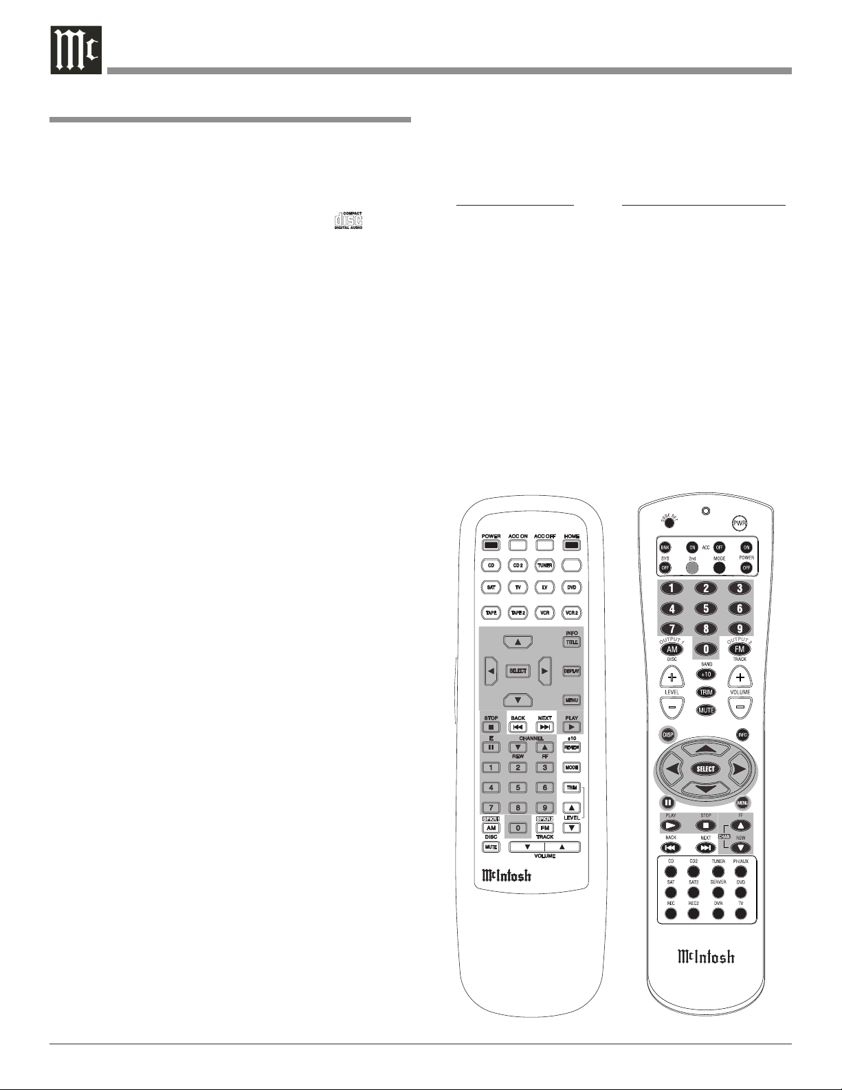
Important Information
labeling of Push-buttons on some McIntosh Remote
Controls and Keypads are different from the supplied
MS750 Remote Control. Refer to the following listing
and illustrations:
MS750 Remote Control Control Center/Preamp/Keypad
Directional (
0-9 0-9
Play
Stop Stop
Pause E
Fast Forward Fast Forward
Reverse Reverse
Ch Channel Up
Ch Channel Down
Option Title
Select Select
Guide Display
Menu Menu
Play
) Directional ( )
McIntosh Remote Controls for A/V
Control Centers and Preamplifiers
6

Introduction
The McIntosh MS750 Music Server offers the latest in
audio technology, providing state of the art audio reproduction with the convenience of instant access to your music
library. When the MS750 is added to a McIntosh Multizone System, the music from this source may be enjoyed in
any part of your home. The advanced design ensures many
years of smooth trouble free operation.
Introduction and Performance Features
• Expand the Music Server System
Multiple MS750s may be connected together with access to
any two MS750s at one time. This provides for unlimited
music storage capacity.
• Digital Audio Inputs and Outputs
There are Coaxial and Optical Digital Audio Inputs/Outputs for connection to other components.
Performance Features
• High Storage Capacity
The MS750 incorporates a massive 750GB Hard Drive
capable of storing the contents of a large CD Music Collection.
• CD Record and Playback Transport
The MS750 has a new advanced transport for fast, quiet
and accurate operation. Transfer music from a CD to the
internal hard drive in less than 5 minutes.
• Graphical User Interface
When connected to a TV/Monitor, the On Screen Display
provides information such as Album Name, Artist Name,
Song Name, Playing Time and Location for each of the selections. This allows for easy song selection from multiple
rooms in your home.
• Automatic CD Identification
When the MS750 is connected to the Internet, it will
automatically look-up information on the loaded CD. This
includes Album Name, Artist Name, Song Name and Playing Time. This information is then stored internally for
later recall.
• Multiple Video Outputs
The MS750 has Component Video Output, S-Video Outputs and Composite Video Outputs for a variety of applications.
• Internet Radio Stations
The MS750 also allows for listening to Internet Radio Stations when connected.
• Select your Music
Listen to the music you want by creating your own play
lists and/or groups of music types. Take the music with
you by recording CDs from your favorite play lists and/or
groups.
• Alphanumeric Fluorescent Display
The display on the MS750 Front Panel provides various
information on the operating status and the current music
playing.
• On Screen Setup
The On Screen Setup allows for customizing various settings such as audio, video, network and external control to
match the components in your system.
• Power Control
The Power Control Input connection provides convenient
Turn-On/Off of the MS750 when connected to a McIntosh
System with Power Control.
• Remote Control
The Remote Control with illuminated push-buttons, pro
vides control of the MS750 operating functions. A Data
Port Connection to a McIntosh A/V Control Center or
Preamplifier allows for convenient system operation using
one Remote Control. An External IR Sensor Input allows
for remote operation when the MS750 is located behind
closed doors.
• Special Power Supply
A fully regulated Power Supply ensures stable noise free
operation even though the power line varies.
• Machined Side Panels
The sides of the MS750 are machined from thick alumi
num panels with a smooth black finish.
• Fiber Optic Solid State Front Panel Illumination
The Illumination of the Glass Front Panel is accomplished
by the combination of custom designed Fiber Optic Light
Diffusers and extra long life Light Emitting Diodes
(LEDs). This provides even Front Panel Illumination and
is designed to ensure the pristine beauty of the MS750 will
be retained for many years.
-
-
7
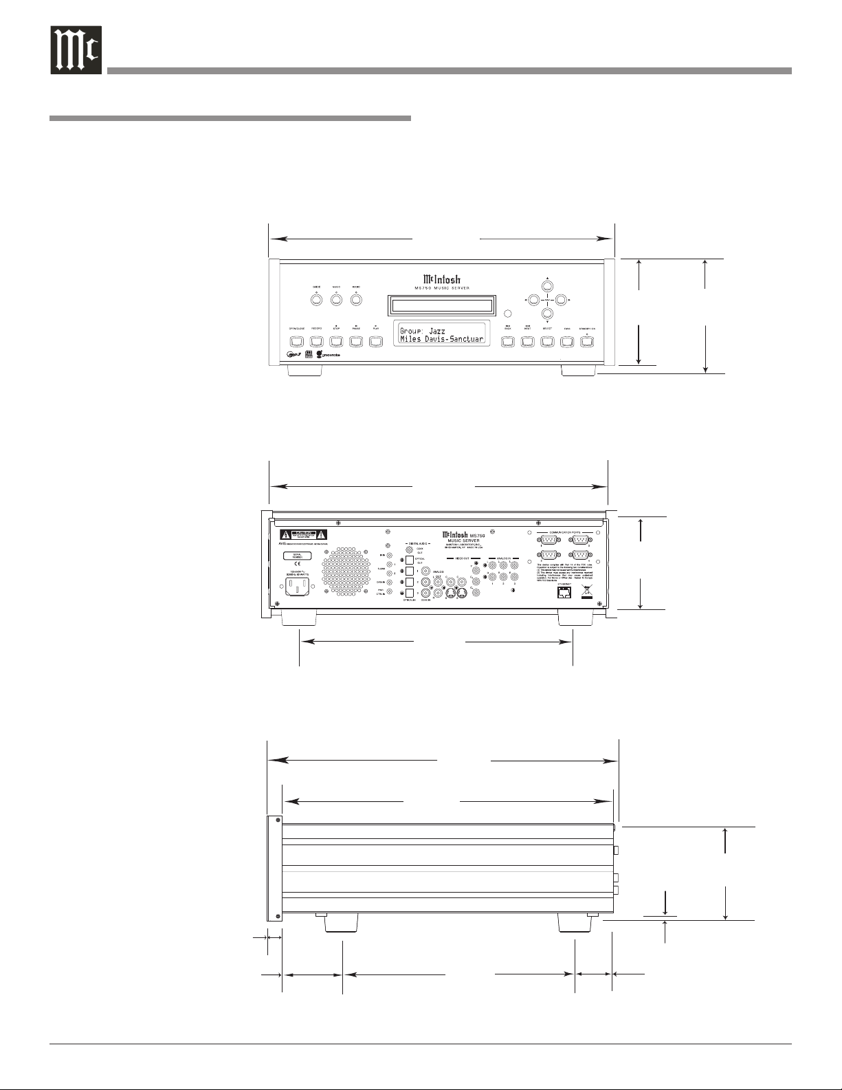
Dimensions
17-1/2"
44.45cm
4-5/8"
11.75cm
6"
15.24cm
14-1/2"
36.83cm
15-7/8"
40.32cm
3/16"
0.48cm
4-13/16"
12.22cm
10-1/2"
26.67cm
13-1/4"
33.65cm
17"
43.18cm
Front View of the MS750
Rear View of the MS750
Side View of the MS750
5-3/8"
13.69cm
13/16"
2.06cm
2"
5.08cm
1-15/16"
4.92cm
The following dimensions can assist in determining the
best location for your MS750. There is additional information on the next page pertaining to installing the MS750
into cabinets.
Dimensions
8

4-7/8"
12.38cm
17-1/16"
43.34cm
Cutout Opening for Custom Mounting
MS750 Front Panel
Custom Cabinet Cutout
8-5/8"
21.91cm
15-1/2"
39.37cm
15-1/16"
38.26cm
1"
2.54cm
Cutout Opening
for Ventilation
Cutout Opening for Ventilation
Support
Shelf
Cabinet
Front
Panel
Chassis
Spacers
MS750 Side View
in Custom Cabinet
MS750 Bottom View
in Custom Cabinet
1-1/16"
2.70cm
12-5/16"
31.27cm
3"
7.62cm
Note: Center the cutout Horizontally on the unit.
For purposes of clarity, the above
illustration is not drawn to scale.
�
Installation
The MS750 can be placed upright on a table or shelf,
standing on its four feet. It also can be custom installed in
a piece of furniture or cabinet of your choice. The four feet
may be removed from the bottom of the MS750 when it is
custom installed as outlined below. The four feet together
with the mounting screws should be retained for possible
future use if the MS750 is removed from the custom installation and used free standing. The required panel cutout,
ventilation cutout and unit dimensions are shown.
Always provide adequate ventilation for your MS750.
Cool operation ensures the longest possible operating life
for any electronic
instrument. Do not
install the MS750
directly above a
heat generating
component such
as a high powered
amplifier. If all the
components are
installed in a single
cabinet, a quiet running ventilation fan
can be a definite
asset in maintaining all the system
components at the
coolest possible
operating temperature.
A custom
cabinet installation
should provide the
following minimum
spacing dimensions
for cool operation.
Allow at least
2 inches (5.08cm)
above the top, 2
inches (5.08cm)
below the bottom,
1 inch (2.54cm)
on each side and
2 inches (5.08cm)
behind the Music
Server, so that
airf low is not obstructed.
Do not block the ventilation holes on the top cover,
bottom cover and rear panel. Allow 1 inch (2.54 cm) in
front of the mounting panel for clearance. When the CD
tray is opened, the panel clearance required in front of
mounting panel is 6-3/4 inches (17.2cm). Be sure to cut out
a ventilation hole in the mounting shelf according to the
dimensions in the drawing.
Installation
9
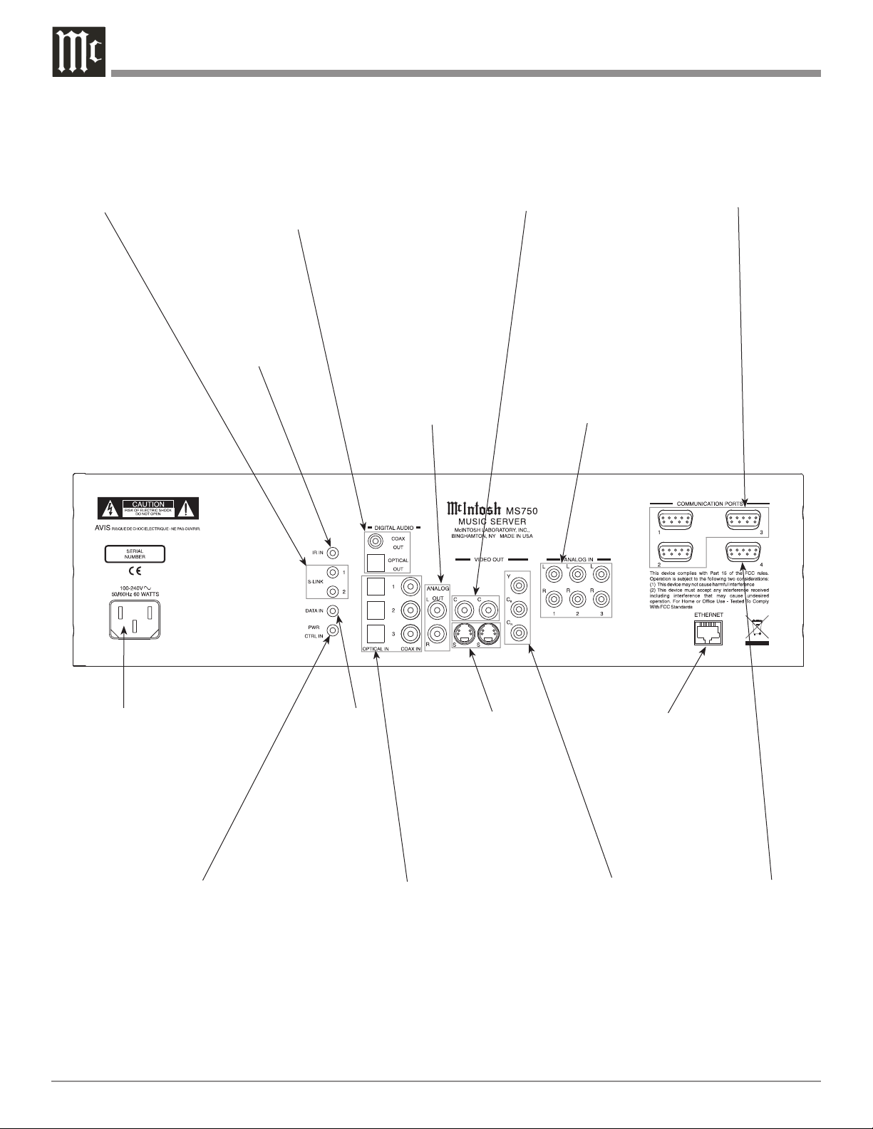
Rear Panel Connections
S-LINK sends
operating data
to external CD
Changers
COAXIAL and OPTICAL
DIGITAL AUDIO OUTPUTS
send signals to a Control Cen
ter with a D/A Converter or a
decoder
IR INput for
connecting an
IR Receiver
ANALOG AUDIO
OUTPUT connects
to the Analog Input
of an A/V Control
Center
COMPOSITE VIDEO OUTPUTS
supply video signals to a Compos-
-
ite Input of an A/V Control Center
or other video component
RS-232C connector
for connection
to control CD
Changers
ANALOG AUDIO
INPUTS connect
to external CD
Changer Audio
Outputs
Connect the MS750
power cord to a live AC
outlet. Refer to information on the rear panel to
determine the correct
voltage for your unit
POWER CONTROL IN
receives turn-on signals
from a McIntosh component
10
DATA IN
receives
-
operat
ing data
from a
S-VIDEO OUTPUTS
supply video signals to
a S-Video Input of an
A/V Control Center or
other video component
McIntosh
Control
Center
OPTICAL and COAXIAL
DIGITAL AUDIO IN
PUTS receive signals from
external CD Changers
ETHERNET Network
Connector for
connecting the MS750
to a Broadband
Ethernet Network
Y OUTPUT connects to the Y
Component Input of the TV/Monitor or other video component.
OUTPUT connects to the
/C
P
B
B
Component Input of the
/C
P
B
B
TV/Monitor or other video component.
OUTPUT connects to the
/C
P
R
R
Component Input of the
/C
P
R
R
TV/Monitor or other video component
RS-232C
connector for
connection
to a remote
control device

How to Connect the MS750
The MS750 has the ability to automatically switch On/Off
when connected to a McIntosh A/V Control Center or
Preamplifier via the Power Control Connections. The Data
Port Connections allow for the remote operation of basic
functions of the MS750 using the McIntosh A/V Control
Center or Preamplifier Remote Control. With an External
Sensor or External Touch Panel connected to the MS750,
remote control operation is possible when the MS750 is
located in a cabinet with the doors closed or from another
room.
The connection instructions below, together with the
Connection Diagram located on the separate folded sheet
“MC1A/1B”, is an example of the MS750 in a typical
audio/video system. Your system may vary from this,
however the actual components would be connected in a
similar manner. It is important to connect both the Digital
and Analog Audio connections between the MS750 and
any external disc changer as no internal conversion takes
place.
For additional information refer to “Connector and
Cable Information” on page 5.
Power Control Connection:
1. Connect a Control Cable from the MS750 POWER
CTRL(Control) IN Jack to the Power Control Out
(ACC) jack on the McIntosh A/V Control Center or
Preamplifier.
Data Control Connection:
2. Connect a Control Cable from the MS750 DATA IN
Jack to the McIntosh A/V Control Center or Preamplifier CD2 or CDR Data In Jack.
Sensor Connection:
3. Optionally connect an external sensor to the MS750
IR jack. Refer to page 6 “Important Information” note
number 4 for additional information.
S-Link Connection:
4. Optionally connect a appropriate cable from the
MS750 S-LINK 1 jack to the first external CD Changer S-Link jack. In a like manner, connect a second CD
Changer to MS750 S-Link 2. Refer to page 6 “Important Information” note number 5 for additional information.
RS-232 Connection:
5. Optionally connect a “null modem” cable from the
MS750 COMMUNICATION PORT1 connector to the
first external CD Changer RS-232 connector. In a like
manner, connect a second and/or third CD Changer to
MS750 COMMUNICATION PORTS 2 and 3 respectively. Refer to page 6 “Important Information” note
number 5 for additional information.
How to Connect the MS750
Ethernet Connection:
6. Optionally connect an appropriate cable from the
MS750 ETHERNET connector to an Ethernet based
network (Hub, Switch, or Router). If no network is
available, a modem may be connected to the MS750
for downloading disc information (Titles, Track
Names and Times) and access to Internet Radio Stations. Refer to page 6 “Important Information” note
number 6 for additional information.
External Touch Panel Connection:
7. Optionally connect an appropriate cable from the
MS750 COMMUNICATION PORT4 connector to an
External Touch Panel Control Base.
Audio Connections:
8. Connect an Audio Cable from the MS750 ANALOG
OUTPUT Jacks to the McIntosh A/V Control Center or
Preamplifier CD2 or CDR Input Jacks.
9. Optionally connect a Coaxial or Optical Cable from
the MS750 DIGTAL AUDIO COAXIAL OUT or OPTICAL OUT Connectors to the McIntosh CD2 or CDR
Coaxial or Optical Input connector.
10. Optionally connect an Audio Cable from the MS750
ANALOG IN 1 jacks to the first external CD Changer
Audio Output. In a like manner, connect a second and/
or third CD Changer to the MS750 ANALOG IN 2 and
3 jacks respectively.
11. Optionally connect an Coaxial or Optical Cable from
the MS750 DIGTAL AUDIO COAXIAL or OPTICAL
IN 1 connector to the first external CD Changer Coaxial or Optical Audio Output. In a like manner, connect a second and/or third CD Changer to the MS750
DIGTAL AUDIO COAXIAL or OPTICAL IN 2 and 3
connectors respectively.
Video Connections:
12. Connect a Video Cable(s) from the MS750 VIDEO
OUT (Component Video, S-Video and/or Composite
Video) Jack to the McIntosh A/V Control Center or
TV/Monitor (Component Video, S-Video and/or Composite Video) Input Jacks.
Note: The Component Video Input used may require
reassignment to the CD2 Input.
13. Optionally connect a Video Cable(s) from the MS750
VIDEO OUT (Component Video, S-Video and/or
Composite Video) Jacks to the External Touch Panel
Control Base.
AC Power Cords Connections:
14. Connect the MS750 AC Power Cord to a live AC
outlet.
15. Connect the remaining components’ AC Power Cords.
11
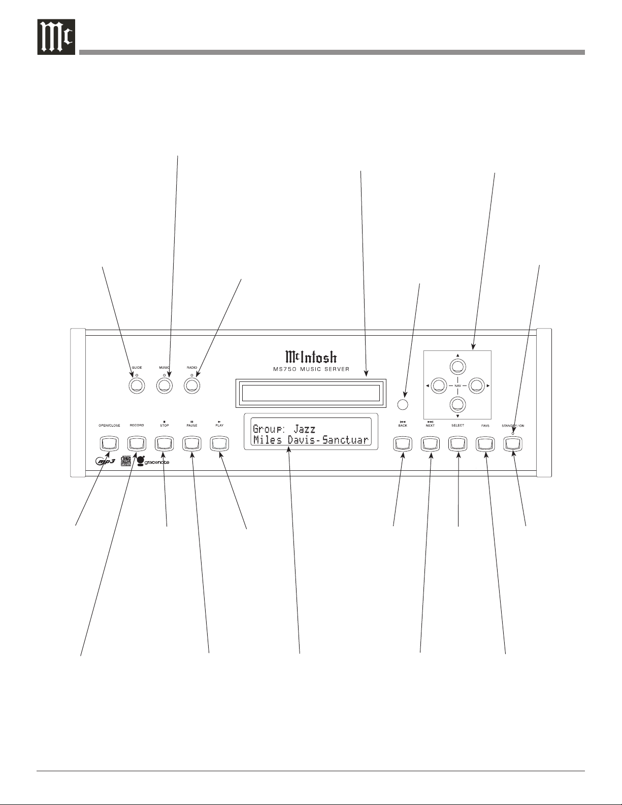
Front Panel Displays and Push-buttons
Selects the On-Screen
GUIDE or Player
Selects the MUSIC
Listen Mode
Selects the Internet
RADIO Listening
Mode
Disc Tray opens
to load and unload
a disc
IR Sensor receives
commands from a
Remote Control
Used to move the
On-Screen cursor
Up, Down, Left or
Right
Standby Power
On Indicator
Opens and
Closes the disc
tray for load
ing or unloading discs
Starts disc
recording
12
-
Stops disc
playback
Starts disc
playback
Use to Pause
during playback
Front Panel
Information
Display
Move rapidly
Backward through
a track during
playback
Move rapidly
Forward through
a track during
playback
Used to Select
the highlighted On-Screen
item
STANDBY/ON
Push-button
switches the
MS750 ON or
OFF (Standby)
and resets the
microprocessors
Press to activate
the Favorites
Playback Mode

Notes
13
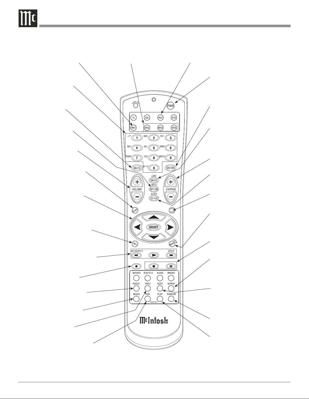
Remote Control Push-Buttons
Press first to send operational commands to the
first MS750 Music Server
Access any numbered
and text based operating
function
Mutes the audio of
a McIntosh Sound
System*
Press to select various
option modes of operation
Adjusts the volume
level up or down of a
McIntosh Sound System*
Activates the On-Screen
Guide or Player Screens
Use to move the onscreen cursor up, down,
left, right; also use to
select the highlighted OnScreen item
Press to display various disc
information. It is displayed
On-Screen and on the Front
Panel Alphanumeric Display
Starts Playback and allows
moving fast forward or reverse
within the track playing
Press first to send operational
command to the second, third or
fourth MS750 Music Servers
Press first to send operational
command to a McIntosh Sound
System
Use to toggle the
power On and Off
to the MS750
Press to enter the previously
pressed push-button (0-9, AZ or symbols)
Press to access various music play
modes such as Normal, Random and
Repeat
Press to change the Channel, Up
or Down; also used to page Up or
Down through various On-Screen
Displays
Press to access the MS750 Setup
Mode
Press to access various OnScreen Guide views
Press to access various OnScreen Menus
Use to stop or pause the music playback
Press to access various Repeat Playback Modes
Activates various Record
Mode Functions
Press to activate the Internet Radio Listening Mode
Press to activate the Music
Listening Mode
Press to return to the
previous selection
Press to add the selected item
to the Favorites Play List or
Jukebox Queue when enabled
Notes: Push-buttons whose function is not identified above are for use with other McIntosh Components. * The McIntosh System
Volume Up/Down and Muting push-button functions require first pressing the RCV Push-button. To return to normal MS750
Remote Control functions first press the MS1 Push-button.
14
Press to advance to the next
selection
Press to select various Random
Playback Modes
Press to start playback of the
selected Favorites or Jukebox
Music when enabled

How to use the Remote Control
How to use the Remote Control
The Remote Control is capable of performing both basic
Operating Functions and Setup Options for the MS750
Music Server.
Notes: Refer to the “How to Operate” and “How to Operate
Setup Mode” Sections of this manual for additional
information using this Remote Control.
Device Selection
This Remote Control is used to operate the McIntosh
MS750 Music Server and the Volume Level/Mute functions of McIntosh Audio/Video Control Centers and
Preamplifiers. When using the Remote Control with the
MS750, first press the MS1 push-button and then press the
push-button for the desired function. It is only required to
press the MS1 push-button once, unless the Remote Control is also being used to control a McIntosh Audio/Video
Control Center or Preamplifiers.
When the Remote Control
is being used to control the
Volume Level/Mute of McIntosh Audio/Video Control Centers and Preamplifiers both
McIntosh Components, first press the RCV push-button
and then the Volume Up/Down or Mute push-button(s).
Pause
Press the PAUSE
Push-button to temporarily stop the
music playback.
Previous and Next
Press the NEXT Push-button to move forward or the
PREVious Push-button to move backward one selection at
a time.
Backspace and Space
Press a BACKSPACE (Reverse)
or SPACE ( Forward)
Push-button to start moving rapidly through music selections. Also used during the manual entering of text names
of Albums/Tracks. Press the BACKSPACE Push-button to
move the cursor to the left or press the SPACE Push-button
to move the cursor to the right.
Option
Press the OPTION Push-button to access the On-Screen
Option Menu.
Setup
Press the SETUP Push-button to access the Initial Setup
Menu.
Play
Press the PLAY
push-button to start playback of the
desired music selection.
Stop
Press the STOP Push-button to stop music playback.
Numbered/Symbol Push-buttons
Press 0 through 9 Push-button(s) to access the desired
music selection, followed by pressing the SELECT Pushbutton.
The text names of Albums/Tracks may be entered manual
ly by pressing the OPTIONS Push-button. Select from the
Options Menu “Edit Disc Info”. Enter the first character
of the name by selecting the appropriate push-button and
then press the push-button once for the first character in
upper case. Repeated rapid presses of the same push-button
will scroll through the other upper case characters assigned
to the push-button followed by lower case versions of the
same characters. Finally the numeric number of the pushbutton will appear, followed by repeating of the same order
again. Use the BACKSPACE / SPACE Push-buttons for the
necessary spaces between words and/or to make corrections.
Mode
Press the MODE Push-button to select one of three differ
ent Music Repeat Modes or two different Random Music
Modes.
Four Direction Arrows
Press an Arrow direction Push-button to move Backward,
Forward, Up or Down through an On-Screen Menu.
Select
Press the SELECT Push-button to confirm and activate a
setup option or options indicated by the on-screen icons.
-
15
How to Operate the Setup Mode
Your McIntosh MS750 has been factory configured for
default operating settings that will allow you to immediately enjoy superb audio. If you wish to make changes to
the factory default settings, a Setup feature is provided
to customize the operating settings using the On-Screen
Display (OSD) Menus.
Notes: The MS750 must be connected to a MONITOR/TV
either through an A/V Control Center or directly,
for setup and use.
The Red LED above the STANDBY/ON switch lights to
indicate the MS750 is in Standby mode. To Switch ON
the MS750, press
the STANDBY/ON
Push-button on the
Front Panel or press
the PWR(Power)
Push-button on the
Remote Control.
Notes: 1. When AC
Power is
initially applied to the MS750 the LED located above
the STANDBY/ON Push-button will flash red until
the start up process is complete and then go into the
Standby Mode. Please wait as this may take several
minutes. Refer to the separate folded sheet “MC1A/
1B” for additional start up information.
2. If power is removed from the MS750 for any reason,
including a power outage or if the unit is unplugged,
the MS750 will automatically return to the Standby
state as soon as power is restored. When it is turned
on again, the MS750 will return to the same source
mode that it was in when power was lost.
3. If the MS750 becomes unresponsive, PRESS and
HOLD the STANDBY/ON Push-button on the Front
Panel of the unit for 4 seconds, releasing when the
standby LED starts blinking.
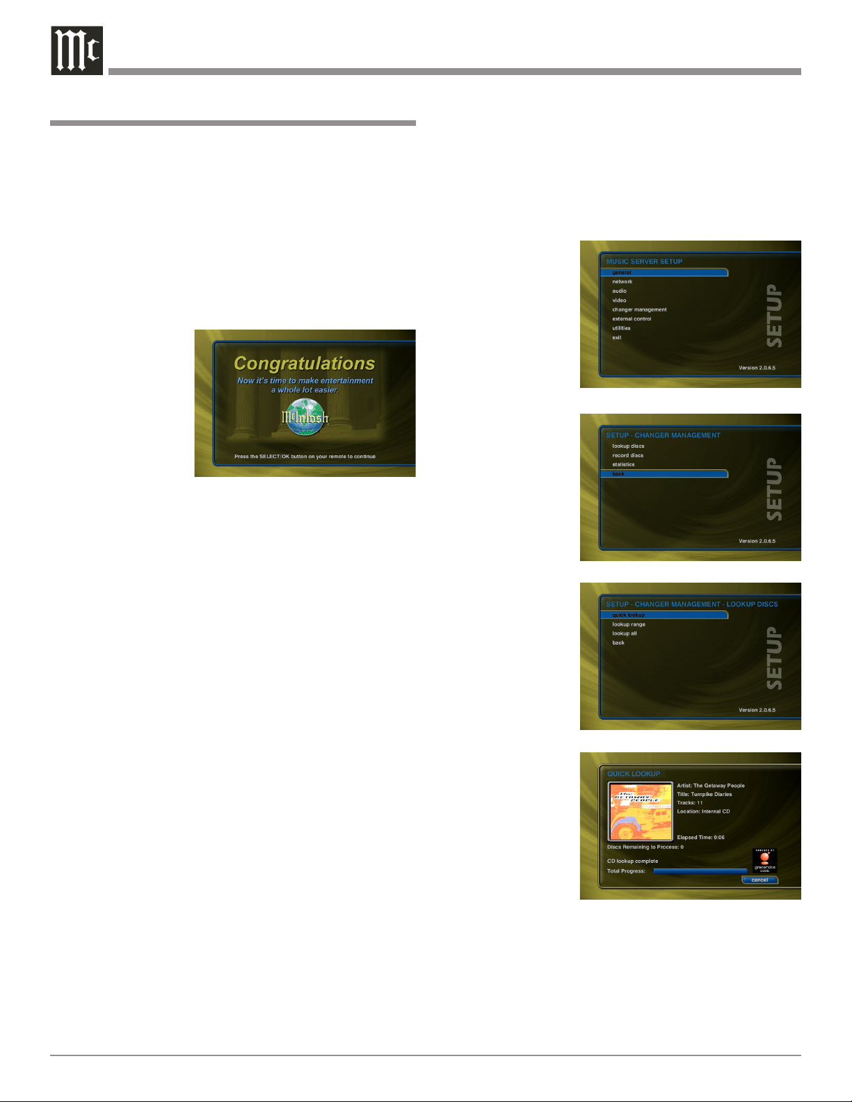
Automatically Getting Disc Information
Once your changers are connected to the MS750 and
loaded with CDs, all you have to do is close the changer
door and in a few seconds the MS750 will begin looking
up the disc information from each disc, in each changer.
Quick Lookup checks each previously empty slot in
the changers to see if any new discs were added, and then
checks each previously occupied slot in the changer to see
if any discs were removed.
One by one, the Table of Contents is read from each CD
and compared to the Gracenote CDDB® using your Internet connection, as the MS750 builds your Music Library.
As each disc is accessed and looked up, the Quick Lookup
screen is updated to display the disc’s information and
cover art. When all of the discs are looked up, the Guide
screen will be displayed.
You can manually run Quick Lookup at any time by
following these steps:
1. Press the SETUP push-button on the remote to display
the Setup menu. Refer to figure 1.
2. Select the
Changer Management menu.
Refer to figure 2.
3. Select the Lookup Discs menu.
4. Select the Quick
Lookup menu.
5. The MS750 will
Figure 1
perform a Quick
Lookup for each
new disc.
Warning:
Quick Lookup
checks for
newly added
and removed
CDs each time
it runs. Do not
remove CDs
and replace
new CDs
into the same
changer slots
without running
Quick Lookup
in-between, or
the MS750 will
not know that
these slots have
changed. If you
want to reuse
the same slots,
first remove
your DVD/
CDs, let Quick
Lookup run,
then add new
DVD/CDs to
the same slots.
Figure 2
Figure 3
Getting Disc Information for a Range of Discs
If you want to lookup the disc information for a specific
range of slots in a changer, you can use the Lookup Range
feature. Follow these steps to lookup a range of changer
slots:
16
 Loading...