

McIntosh MI254 Owner's Manual
McIntosh Laboratory, Inc. 2 Chambers Street Binghamton, New York 13903-2699 Phone: 607-723-3512 www.mcintoshlabs.com
MI254
Four Channel
Power Amplifier
Owner’s Manual
Important Safety Information is supplied in a separate document “Important Additional Operation Information Guide”
Thank You
Your decision to own this McIntosh MI254 Four Channel Power Amplifier ranks you at the very top among discriminating music listeners. You now have “The Best.” The McIntosh dedication to “Quality,” is assurance that you will receive many years of musical enjoyment from this unit.
Please take a short time to read the information in this manual. We want you to be as familiar as possible with all the features and functions of your new McIntosh.
Please Take A Moment
The serial number, purchase date and McIntosh Dealer name are important to you for possible insurance claim or future service. The spaces below have been provided for you to record that information:
Serial Number:________________________________
Purchase Date:_ _______________________________
Dealer Name:_ ________________________________
Technical Assistance
If at any time you have questions about your McIntosh product, contact your McIntosh Dealer who is familiar with your McIntosh equipment and any other brands that may be part of your system. If you or your Dealer wish additional help concerning a suspected problem, you can receive technical assistance for all McIntosh products at: McIntosh Laboratory, Inc.
2 Chambers Street Binghamton, New York 13903 Phone: 607-723-3512
Fax: 607-724-0549
Customer Service
If it is determined that your McIntosh product is in need of repair, you can return it to your Dealer. You can also return it to the McIntosh Laboratory Service Department. For assistance on factory repair return procedure, contact the McIntosh Service Department
at: McIntosh Laboratory, Inc. 2 Chambers Street
Binghamton, New York 13903 Phone: 607-723-3515
Fax: 607-723-1917
Table of Contents |
|
|
Safety Instructions...................................................... |
|
2 |
(Separate Sheet).................... |
Important Additional |
|
|
Operation Information Guide |
|
Thank You and Please Take a Moment....................... |
2 |
|
Technical Assistance and Customer Service............... |
2 |
|
Table of Contents......................................................... |
|
2 |
General Information.................................................... |
|
2 |
Connector and Cable Information............................... |
3 |
|
Introduction................................................................. |
|
3 |
Performance Features.................................................. |
|
3 |
Dimensions.................................................................. |
|
4 |
Installation................................................................... |
|
5 |
Rear Panel Connections, Switches and Selection..... |
6-7 |
|
Output Terminals and How to Connect.................. |
8-13 |
|
Front Panel Displays and Push-button....................... |
14 |
|
How to Operate.......................................................... |
|
15 |
Photos................................................................... |
|
16-17 |
Specifications............................................................ |
|
18 |
Packing Instruction................................................... |
|
19 |
General Information
1.For additional connection information, refer to the owner’s manual(s) for any component(s) connected to the MI254.
2.The MI254 mutes the speaker output for approximately two seconds when first turned on.
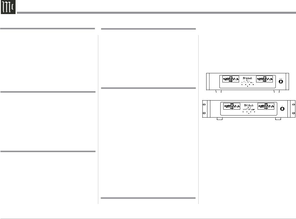
3.Included with the MI254 and located in the Owner’s Manual Packet are two Side Rack Mounted Brackets and screw fasteners. Below are graphic images of the MI254 with and without the Side Rack Mounted Brackets attached. Refer to page 5 for installing the Side Rack Mount Brackets.
MI254 4 Channel Power Amplifier
MI254 4 Channel Power Amplifier with
Side Rack Mount Brackets installed
4.For the best performance and safety it is important to always attach a single Loudspeaker with an 8 Ohm or 4 Ohm impedance to the Channel 1 - Channel 4 output terminals. Refer to “How to Connect” pages 8 thru 13.
Note: The impedance of a Loudspeaker actually varies as the Loudspeaker reproduces different frequencies. As a result, the nominal impedance rating of the Loudspeaker (usually measured at a midrange frequency) might not always agree with the impedance of the Loudspeaker at low frequencies where the greatest amount of power is required. Contact the Loudspeaker Manufacturer for additional information about the actual impedance of the Loudspeaker before connecting
it to the McIntosh MI254.
Copyright 2018 © by McIntosh Laboratory, Inc.
2

General Information, con,t and Cable Information, Introduction and Performance Features
5. In the event the MI254 Channel(s) over heat, due to improper ventilation or Loudspeaker Impedance, the protection circuits will activate. The Front Panel Channel LED will change color and the audio will be muted. Refer to page 15. When the MI254 has returned to a safe operating temperature, Channel(s) normal operation will resume.
6.For additional information on the MI254 and other McIntosh Products please visit the McIntosh Website at www.mcintoshlabs.com.
Connector and Cable Information
XLR Connectors
Below is the Pin configuration for the XLR Balanced Input, Input/Output Connectors on the MI254. Refer to the diagram for connection: 

PIN 1: Shield/Ground
PIN 2: + Input/Output
PIN 3: - Input/Output
Power Control Connector
The MI254 Power Control Input receives an On/Off signal from +5 to +12 volts. The Power Control Output will in turn provide a +12 volt Output Signal with a total current up to 50mA. An additional connection
is for controlling the illumination |
Power |
|
|
|
|||
of the MI254 Meter Power Output |
|
||
Control |
|||
Indicators. The 3.5mm stereo mini |
|||
Meter |
|||
phone plug connects to a McIntosh |
Illumination |
||
Control Ground |
|||
Preamplifier or A/V Control Center |
|||
|
|
||
Power Control Output. |
|
|
|
Output Terminal Connector
When cables with spade lugs are used for Loudspeaker Connection, the spade lugs need an opening of at least 3/10 inch (7.6mm)
Introduction
Now you can take advantage of traditional McIntosh standards of excellence in the MI254 Power Amplifier. The Four Channel Power Amplifier produces high power output per channel and will drive quality Loudspeakers to a high level of performance. The MI254 reproduction is sonically transparent and absolutely accurate. The McIntosh Sound is “The Sound of the Music Itself.”
Performance Features
• Power Output
The MI254 consists of Four Power Amplifier Channels, each capable of 250 watts into 8 ohms 300 watts into 4 ohms Loudspeakers with distortion less than 0.025%.
• Loudspeaker Guard
The McIntosh Loudspeaker Guard Circuit prevents the amplifier from being over driven into clipping, with its harsh distorted sound that can damage your valuable Loudspeakers.
• Versatile Operation
The MI254 can provide power amplification for four channels in a single Zone A/V System or two channels for each of a Dual Zone A/V System.
• Balanced, Unbalanced and Bus Inputs
There are Balanced, Unbalanced and Bus Connections for all four Power Amplifier Input Channels.
• Sentry Monitor and Thermal Protection
McIntosh Sentry Monitor power output stage protection circuits ensure the MI254 will have a long and trouble free operating life. Built-in Thermal Protection circuits guard against overheating.
• Illuminated Power Meters
The Illuminated Power Output Watt Meters on the MI254 are peak responding, and indicates the Power Output of the amplifiers.
• Power Control
The McIntosh Power Control Circuit allows for remote turn-on of the MI254 Power Amplifier from a McIntosh A/V Control Center or Preamplifier for a single or dual Zone System.
• Special Power Supply
A regulated Power Supply ensures stable noise free operation even though the power line varies.
• LED Solid State Front Panel Illumination
The even Illumination of the Front Panel is accomplished by extra long life Light Emitting Diodes (LEDs). The Metal and Glass Front Panel ensures the pristine beauty of the MI254 will be retained for many years.
3

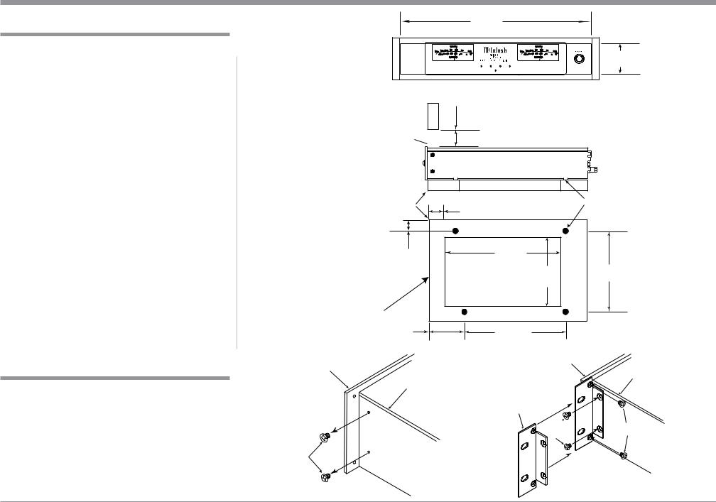
Dimensions
Dimensions
The following dimensions can assist in determining the best location for your MI254.
Front View of the MI254
17-1/2"
44.5cm
3-15/32" 4-5/16" 8.8cm 11.0cm
Front View of the MI254 with Side Mount Brackets |
Side View of the MI254 |
|
19" |
||
|
||
48.3cm |
18-1/2" |
|
|
||
|
47.0cm |
|
|
17-1/16" |
|
|
43.3cm |
3/16" 3-1/4"
.5cm 8.2cm
Rear View of the MI254 |
.25" |
|
|
|
16-1/2" |
.64cm |
|
|
|
2.0" |
13-19/32" |
1-5/16" |
||
41.9cm |
||||
|
5.0cm |
34.7cm |
3.4cm |
13-1/4"
33.7cm
4
Installation
Installation
The MI254 needs to be placed upright on its four feet. It also can be custom installed. Remove the four feet when it is custom installed and retain them with the fastening screws for possible future use. The required panel cutout, ventilation cutout and unit dimensions are shown in the drawing on the right side of this page.
It is necessary to provide adequate ventilation for cool operation, ensuring long life for the MI254. Do not install the MI254 above heat generating components. When the MI254 is installed in a cabinet with other components, use a ventilation fan to provide cool operating temperature.
A custom cabinet installation needs to provide the following minimum spacing for cool operation:
Allow at least 3 inches (7.6cm) above the top, 2 inches (5.08cm) below the bottom, 3 inches (7.62cm) behind the rear panel and 2 inches (5.08cm) on each side of the MI254, providing
airflow. Allow 2-1/2 inches (6.35 cm) in front of the mounting1 panel for clearance. Be sure to cut out a ventilation hole in the mounting shelf according to the dimensions in the drawing.
1When the MI254 is installed together with other McIntosh Components, check clearances on all components before proceeding.
Installation of Side Rack Mount Brackets
When desired, to install MI254 Side Rack Mounting Brackets, follow the steps below for one side at a time:
1.Refer to figure A to remove the two side screws and save them for possible future use.
2.Position the Side Rack Mounting Bracket as illustrated in figure B. Then attach the Bracket to the Front and Side Panel of the MI254, using the screws supplied with the Bracket.
3.Perform steps 1 and 2 to mount the second Bracket to the other side of the MI254.
|
|
16-7/8" |
|
|
42.8cm |
MI254 Front Panel |
|
3-1/4" |
|
8.2cm |
|
Custom Cabinet Cutout |
|
|
|
3" |
Cutout Opening for Custom Mounting |
|
|
7.6cm
Cabinet Front  Panel
Panel
Opening  for Ventilation
MI254 Side View
in Custom Cabinet
MI254 Bottom View
in Custom Cabinet
Note: Center the cutout Horizontally on the unit. For purposes of clarity, the above illustration is not drawn to scale.
|
Cutout Opening for Ventilation |
|
|
Support |
|
|
Chassis |
Shelf |
25/32" |
|
Spacers |
|
2.0cm |
|
|
29/32" |
10-9/16" |
|
|
26.9cm |
|
|
|
2.4cm |
|
14-7/16" |
15" |
|
Cutout Opening |
||
|
38.1cm |
||
|
36.2cm |
||
|
for Ventilation |
|
|
|
|
|
|
3" |
11-19/32" |
|
|
7.6cm |
29.7cm |
|
|
Front Panel |
Front Panel |
|
|
|
Side Panel |
||
|
|
||
|
Side Panel |
|
|
|
Side Rack |
|
|
|
Mounting |
|
|
|
Bracket |
|
|
Remove two |
Supplied |
Supplied |
|
Screws |
|||
Screws |
|||
Screws from |
|
||
|
|
||
the Chassis |
|
|
|
Sidewall |
|
|
|
and save |
|
|
|
them |
|
|
|
Figure A |
Figure B |
|
5
|
|
|
|
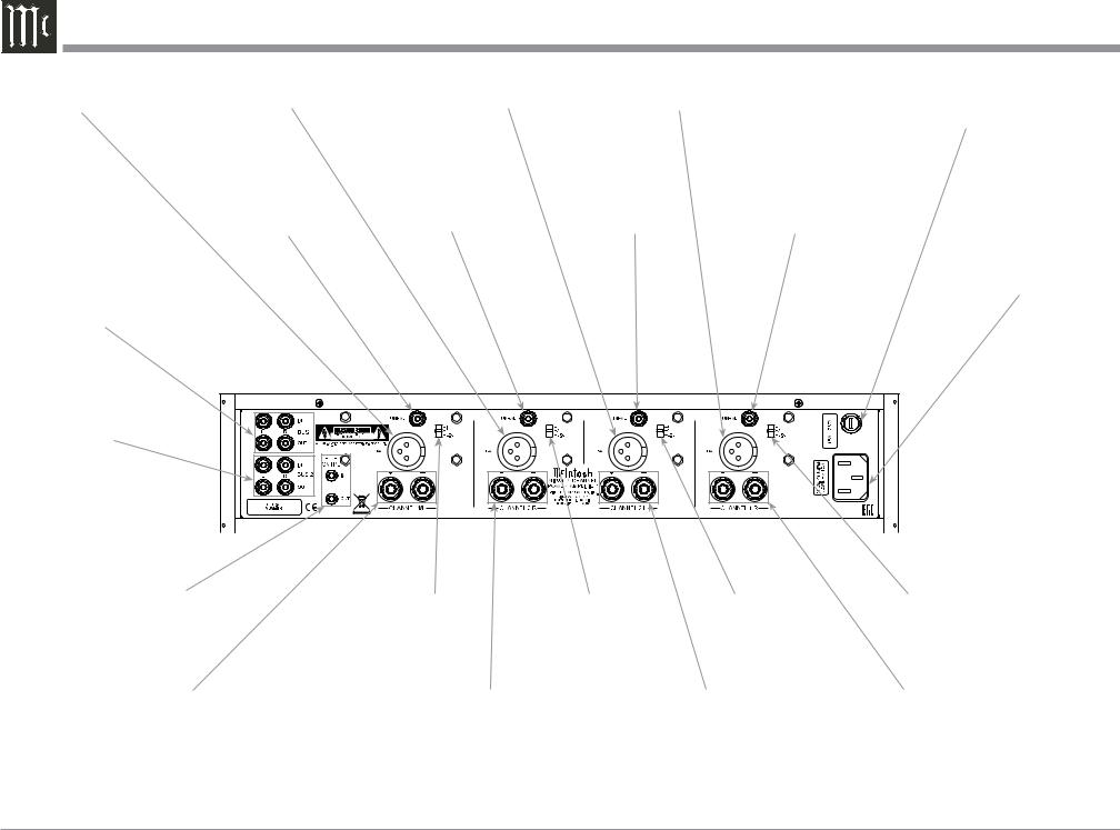
Rear Panel Connections and Switches |
BALanced Input |
BALanced Input |
BALanced Input |
BALanced Input CHAN- |
Main Fuse, refer to the |
CHANNEL 4/Left |
CHANNEL 3/Right |
CHANNEL 2/Left |
NEL 1/Right |
Rear Panel for the correct |
|
|
|
|
fuse size and rating |
UNBALanced Input |
UNBALanced Input |
UNBALanced Input |
UNBALanced Input |
CHANNEL 4/Left |
CHANNEL 3/Right |
CHANNEL 2/Left |
CHANNEL 1/Right |
Connect the MI254 Power Cord to a live
AC Outlet
BUS 1 Left and Right INput and OUTput Connections1 Jacks
BUS 2 Left and Right INput and
OUTput Connections1 Jacks
PWR CNTRL (Power Control) |
|
|
|
|
|
|
|
|
IN receives turn On/Off signal |
|
|
|
|
|
|
||
from a McIntosh component. |
|
|
|
|
|
|
||
PWR CNTRL (Power Control) |
CHANNEL 4/Left |
CHANNEL 3/Right |
CHANNEL 2/Left |
CHANNEL 1/Right |
||||
OUT sends a turn On/Off signal |
||||||||
Input Selector Switch1 |
Input Selector Switch1 |
Input Selector Switch1 |
Input Selector Switch1 |
|||||
to another McIntosh Component |
|
|
|
|
|
|
||
CHANNEL 4/Left Output |
CHANNEL 3/Right Output |
CHANNEL 2/Left Output |
CHANNEL 1/Right Output |
|||||
Connections for a 4 ohm |
Connections for a 4 ohm or |
Connections for a 4 ohm or |
Connections for a 4 ohm or |
|||||
or 8 ohm Loudspeaker |
8 ohm Loudspeaker |
|
8 ohm Loudspeaker |
8 ohm Loudspeaker |
||||
1 Refer to page 7 for detailed information about utilization of the CHANNEL 1-4 Input Switches and the functioning of the BUS 1-2 INput and OUTput connection jacks
6
 Loading...