


STEREO
PREAMPLIFIER C20
|
GENERAL DESCRIPTION |
|
|
|
|
|
|
|
|
|
|
|
|
|
|
|
|
|
|
|
|
|
|
|
1 |
||||||
|
|
|
|
|
|
|
|
|
|
|
|
|
|
|
|
|
|
|
|
||||||||||||
|
|
|
|
|
|
|
|
|
|
|
|
|
|
|
|
|
|
|
|
|
|
|
|
||||||||
|
TECHNICAL |
DESCRIPTION |
|
|
|
|
|
|
|
|
|
|
|
|
|
|
|
|
|
|
1 |
||||||||||
|
|
|
|
|
|
|
|
|
|
|
|
|
|
||||||||||||||||||
|
Mechanical Specifications |
|
|
|
|
|
|
|
|
|
|
|
|
|
|
2 |
|||||||||||||||
|
Electrical Specifications |
|
|
|
|
|
|
|
|
|
|
|
|
|
|
2 |
|||||||||||||||
|
|
|
|
|
|
|
|
|
|
|
|||||||||||||||||||||
|
FRONT PANEL FACILITIES |
|
|
|
|
|
|
|
|
|
|
|
|
|
|
2 |
|||||||||||||||
|
|
|
|
|
|
|
|
|
|
|
|
||||||||||||||||||||
|
INSTALLATION |
|
|
|
|
|
|
|
|
|
|
|
|
|
|
|
|
|
|
|
|
|
|
|
|
|
|
5 |
|||
|
|
|
|
|
|
|
|
|
|
|
|
|
|
|
|
|
|
|
|
|
|
|
|
|
|
|
|||||
|
CONNECTING |
|
|
|
|
|
|
|
|
|
|
|
|
|
|
|
|
|
|
|
|
|
|
|
|
|
|
6 |
|||
|
A-C Connections |
|
|
|
|
|
|
|
|
|
|
|
|
|
|
|
|
|
|
|
|
|
|
|
|
6 |
|||||
|
Input |
Connections |
|
|
|
|
|
|
|
|
|
|
|
|
|
|
|
|
|
|
|
|
|
7 |
|||||||
|
Output Connections |
|
|
|
|
|
|
|
|
|
|
|
|
|
|
|
|
|
|
|
|
9 |
|||||||||
|
|
|
|
|
|
|
|
|
|
|
|
|
|
|
|
|
|
|
|
|
|||||||||||
|
Ground Connections (Program Sources) |
|
|
|
|
|
9 |
||||||||||||||||||||||||
|
|
||||||||||||||||||||||||||||||
|
OPERATING |
INSTRUCTIONS |
|
|
|
|
|
|
|
|
|
|
|
|
10 |
||||||||||||||||
|
Balancing a Stereo |
|
|
System |
10 |
||||||||||||||||||||||||||
|
|
|
|
|
|
|
|
|
|
|
|
|
|
|
|
|
|
||||||||||||||
TABLE OF CONTENTS |
To Adjust for Balance in the Treble |
|
|||||||||||||||||||||||||||||
Range |
|
|
|
|
|
|
|
|
|
|
|
|
|
|
|
|
|
|
|
|
|
|
|
|
|
|
10 |
||||
|
|
|
|
|
|
|
|
|
|
|
|
|
|
|
|
|
|
|
|
|
|
|
|||||||||
|
To Adjust for Amplitude Balance in |
10 |
|||||||||||||||||||||||||||||
|
the |
Bass Range |
|
|
|
|
|
|
|
|
|
|
|
|
|
|
|
|
|
|
|
||||||||||
|
Adjusting Phase |
|
|
|
|
|
|
|
|
|
|
|
|
|
|
|
|
|
|
|
|
|
10 |
||||||||
|
Listening to a Stereo Record |
|
|
|
|
|
|
|
10 |
||||||||||||||||||||||
|
To Adjust the Balance Control After the |
11 |
|||||||||||||||||||||||||||||
|
System has been Balanced |
||||||||||||||||||||||||||||||
|
Adjusting for Special Effects |
|
|
|
|
|
|
|
|
11 |
|||||||||||||||||||||
|
Using the C20 with a Stereo Tuner |
|
|
|
|
11 |
|||||||||||||||||||||||||
|
Using the C20 with a Stereo Tape Machine_ |
11 |
|||||||||||||||||||||||||||||
|
Using the C20 Front Panel Tape Jacks |
|
|
|
12 |
||||||||||||||||||||||||||
|
Using the C20 with Tape Decks |
|
|
|
12 |
||||||||||||||||||||||||||
|
Using the C20 with |
Microphones for Stereo. |
12 |
||||||||||||||||||||||||||||
|
Monophonic Record |
|
Settings |
12 |
|||||||||||||||||||||||||||
|
Operating Curves |
|
|
|
|
|
|
|
|
|
|
|
|
|
|
|
|
|
|
|
14 |
||||||||||
|
GUARANTEE |
|
|
|
|
|
|
|
|
|
|
|
|
|
|
|
|
|
|
|
|
|
|
|
|
|
|
|
|
|
16 |
|
|
|
|
|
|
|
|
|
|
|
|
|
|
|
|
|
|
|
|
|
|
|
|
|
|
|
|
|
|
|
|
C2 0
C20 STEREOPHONIC PREAMPLIFIER
GENERAL DESCRIPTION
The Mclntosh C20 Stereophonic Pre-amplifier is a control center for any stereophonic sound system. This control center is necessary to accurately perform four specific functions to increase the enjoyment of stereo.
First, the control center amplifies weak electrical impulses. As the record rotates on the turntable, undulations in the grooves move the pick-up stylus approximately one-thousandth of an inch, in any direction, from the rest position. From this slight mechanical movement, the pick-up stylus generates a weak electrical impulse on the order of a few thousandths of a volt. To amplify and preserve the character of such an electrical impulse, the finest amplifier performance is required.
Second, every sound system is used in a different acoustical environment. The tone balance of the music
is affected by variations in environment. Also, people listening to the music have varying ideas of correct tone balance. To adequately compensate for these conditions, a high-quality control center is needed.
Third, there is a great variety of stereophonic and monophonic records manufactured today, both domestic and foreign. The control center must provide record compensation for a great variety of recordings.
Fourth, with programs originating from a variety of sources such as tuners, records, tape machines, microphones, etc., a control center is needed to select and switch these sources separately or in combination.
All of these jobs are performed with excellence by the C20 and yet this instrument is easy to mount, simple to operate, and is the finest in appearance.
TECHNICAL DESCRIPTION
You now own the finest expression of stereo craftsmanship . . . designed and built to fulfill your needs. Through direct consumer contact, a unique Mclntosh marketing research program determines the application of electronic and mechanical engineering to fit your needs. Relentless research by Mclntosh engineers improves the selection of materials and the circuits in which they are used. It is this total concept of craftsmanship directed to consumer satisfaction that has maintained the Mclntosh reputation for excellence in performance, quality, and reliability.
Perhaps you would like to know a few of the features developed through research based on consumer needs that place your C20 Pre-amplifier above all other pre-amplifiers.
An example of the unique mechanical construction throughout is emphasized on the back panel where lowvoltage program sources are connected to the C20. This portion of the panel is cut out and mounted on small electrical insulators. The ground circuit is connected to the main chassis at only one point. By breaking the path for circulating hum currents in this manner, the hum and unwanted noises induced in other stereo systems when used with various program sources and combinations of program sources are eliminated.
Hum noises are also introduced into stereo systems by the magnetic fields produced by the power transformer windings. The greatest care went into the design and construction of the power transformer in your C20. It is wound in such a way that the magnetic fields produced by the windings tend to cancel. This is accomplished by splitting the windings into two segments. Further reduction of the magnetic field intensity is achieved through the use of additional magnetic and electrical shielding. With these construction improve-
ments the hum noises introduced by ordinary preamplifiers are eliminated by the C20.
Nearly all of the small resistor and capacitor component parts in the C20 are mounted on military-type terminal boards. This specialized construction prevents damaging mechanical strains. In addition it makes servicing, if ever required, much easier and more effective.
The mechanical layout of the C20 allows maximum separation of the left and right channels. The terminal board at the rear of the C20 is associated with the right channel and the terminal board at the front with the left channel. C20 terminal boards are constructed of natural bakelite because of its low-volume resistivity. This prevents the gradual increase of electrical noise common to other terminal board materials after continued use of the control center.
The C20 is the only control center that has an illuminated front panel to provide convenient reading under low-level lighting conditions. This feature is of particular importance when a closet is adapted to house stereo equipment.
Front panel tape input jacks are another exclusive feature provided by the C20. With the start of stereo FM broadcasting it will be important to tape and preserve those special programs that will otherwise never be heard again. This feature will be greatly appreciated by you and your friends when recording on portable tape machines.
Only extensive research and planning combined with skilled engineering and manufacturing knowhow, directed toward consumer needs, can produce such a fine electronic instrument.
1
MECHANICAL SPECIFICATIONS
DIMENSIONS
Chassis: 14-1/2 inches wide; 4-1/2 inches high; 12 inches deep
Front Panel: 15-5/8 inches wide; 4-7/8 inches high
Front Panel Mounting Space Required: 16-3/8 inches wide; 5 inches high
WEIGHT
Chassis: 18 pounds
Shipping Weight: 28.5 pounds
FINISH
Anodized gold and black (front panel)
ELECTRICAL SPECIFICATIONS
POWER REQUIREMENTS 117 volts, 50/60 cycles, ac, 35 watts
INPUT SENSITIVITY AND INPUT IMPEDANCE Auxiliary: 0.25 volt; 470,000 ohms
Tape: 0.25 volt; 470,000 ohms Tuner 1: 0.25 volt; 470,000 ohms Tuner 2: 0.25 volt; 470,000 ohms
Phono 1: 2 to 10 millivolts; 47,000 ohms for low-output cartridge
10 to 70 millivolts; 47,000 ohms for high-output cartridge
0.1 volt; 220 mmf in series with 47,000 ohms for Xtal or ceramic cartridge
Phono 2: Same as phono 1
Tape Head 1: 2 to 10 millivolts; 47,000 ohms for lowoutput head
10 to 70 millivolts; 267,000 ohms for high-output head
Tape Head 2: Same as tape head 1
Tape Compare (Monitor): 0.25 volt; 115,000 ohms FREQUENCY RESPONSE
±0.5db; 20 to 20,000 cycles
DISTORTION
Less than 0.2% at rated output, 20 to 20,000 cycles
HUM AND NOISE High-level inputs: 85 db below rated output
Low-level inputs: less than 2 microvolts at input terminals
MAIN OUTPUT 2.5 volts with rated input
2 output jacks in parallel for each channel
TAPE OUTPUT
0.25 volt with rated input
1 output jack for each channel
LEFT PLUS RIGHT OUTPUT
2.5 volts from generator impedance of 23,000 ohms
VOLTAGE AMPLIFICATION
Low-level inputs to Main Output:
Low-level inputs to Tape Output:
High-level inputs to Main Output: High-level inputs to Tape Output: Tape Compare (Monitor) input to
Main Output: 10 to 1 (20 db)
A-C AUXILIARY OUTLETS
1 unswitched for tape machine or turntable, colored Red
4 switched, colored Black
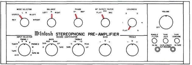
FRONT PANEL FACILITIES
Figure 1. C20 Front Panel
2
INPUT SELECTOR
INPUT SELECTOR
|
PHONO 1 |
2 |
S M S |
TUNER |
PHONO 2 |
1 |
M |
TAPE |
1 |
AUX |
TAPE HD |
2 |
This ten-position program switch connects the C20 as follows:
AUX ... any auxiliary service, such as a television set, an extra tuner, or any other program source requiring flat amplification.
TAPE . . . any self-contained tape machine (tape machine having its own playback preamplifier).
TUNER 1 & 2 . . . AM and FM outputs from a stereo tuner or a pair of stereo tuners.
PHONO 1 & 2 — S & M ... stereo or monophonic operation with the following types of phono cartridges.
a.Constant amplitude cartridges such as crystal, ceramic, or frequency-modulated devices.
b.Magnetic cartridges having an output of 10mv or more. Maximum input voltage for this output is 70mv.
c.Magnetic cartridges having an output of less than 10mv.
TAPE HEAD—1 & 2 ... a tape deck or a pair of tape decks that do not contain their own playback preamplifiers. Two types of tape head outputs can be used in this position.
a.Tape heads having an output of less than 10mv.
b.Tape heads having an output of 10mv or more. Maximum input voltage for this output is 70mv.
MODE SELECTOR
MODE SELECTOR
L |
R |
STEREO |
M LEFT |
REV |
M RIGHT |
This six-position switch connects the C20 for proper left-right distribution of sound for the program source selected. Its positions are as follows:
REV . . . connects left channel to right speaker, right channel to left speaker, corrects for leftright reversal of program.
STEREO . . . this is the normal stereo MODE SELECTOR position; left channel to left speaker, right channel to right speaker.
L . . . left channel to left speaker, no program to right speaker.
R . . . right channel to right speaker, no program to left speaker.
M LEFT . . . left channel only to both speakers.
M RIGHT . .. right channel only to both speakers.
RECORD COMPENSATOR
|
RECORD |
COMPENSATOR |
|
|
BASS |
TREBLE |
|
400 |
RIAA |
-10 |
-12 |
300 |
UP |
-5 |
RIAA |
0 |
TAPE |
TAPE |
LP |
These controls are used to correct for program equalization introduced by the recording process. Table 3 gives the recommended settings of the RECORD COMPENSATOR controls of the C20 for monophonic recordings.
BASS AND TREBLE
BASS |
TREBLE |
- ° + |
- ° + |
There are two tone controls on the C20—BASS and TREBLE.
BASS . . . clockwise rotation increases bass loudness; counterclockwise rotation decreases bass loud ness.
TREBLE . . . clockwise rotation increases treble loudness; counterclockwise rotation decreases treble loudness.
PHASE
PHASE 0° 180°
This two-position switch reverses the phase in the left channel to correct for speaker or program phasing.
3
BALANCE
BALANCE
LEFT 0 RIGHT
This control balances the C20 for unequal program sources.
LEFT . . . turning the control to the left slowly reduces the right channel to no output and accents the left channel.
RIGHT . . . turning the control to the right slowly reduces the left channel to no output and accents the right channel.
HF CUTOFF FILTER
HF CUTOFF FILTER
9KC
FLAT 5KC
This three-position switch minimizes surface noise when reproducing old, badly worn recordings. Its positions are as follows:
FLAT... filter disconnected.
9KC .. . rolls off response sharply starting at 9KC.
5KC . . . rolls off response sharply starting at 5KC.
LOUDNESS
L0UDNESS
2 3
I |
4 |
FLAT 5
Music reproduced at very low volume loses its bass and treble due to a selective shift in sensitivity of human hearing. This effect is known as the FletcherMunson hearing characteristics. (See page 15, Figure 13.) The LOUDNESS control corrects for this effect.
RUMBLE FILTER
RUMBLE
FILTER
IN-ON
With the RUMBLE FILTER button pushed to the IN position, low-frequency rumble noise below 60 cps created by a turntable or changer and undesirable acoustically coupled feedback are reduced.
TAPE JACK
TAPE
JACK
IN-PLAYBACK
OUT-RECORD
This pushbutton controls the signal direction to or from the front panel telephone jacks.
IN-PLAYBACK . . . TAPE input is switched from rear tape jacks to front panel telephone jacks.
Any program originating from a portable machine connected to the C20 can be heard by rotating the INPUT selector to the TAPE position.
OUT-RECORD . . . connect signals from the rear tape jacks to the INPUT SELECTOR TAPE position. Any program picked up by the C20 is connected to the portable machine for recording,
TAPE COMPARE
TAPE
COMPARE
IN-TAPE
This pushbutton makes it possible to instantaneously compare the recorded material with the source signal. TAPE COMPARE jacks are provided on the back panel to accept a signalfrom a tape recorder with a monitor head and preamplifier. When the TAPE COMPARE pushbutton is in the out position, the program source is fed through the power amplifiers and the loudspeakers. When the TAPE COMPARE pushbutton is in the IN position (depressed), the signal source becomes the monitored program from the recorded tape and is fed through the power amplifiers and loudspeakers.
IMPORTANT
When the TAPE COMPARE pushbutton is depressed, signal from any other source will not be heard from the loudspeakers. When not in use, make sure the pushbutton is in the out position.
4
 Loading...