

www.mcisolutions.ca
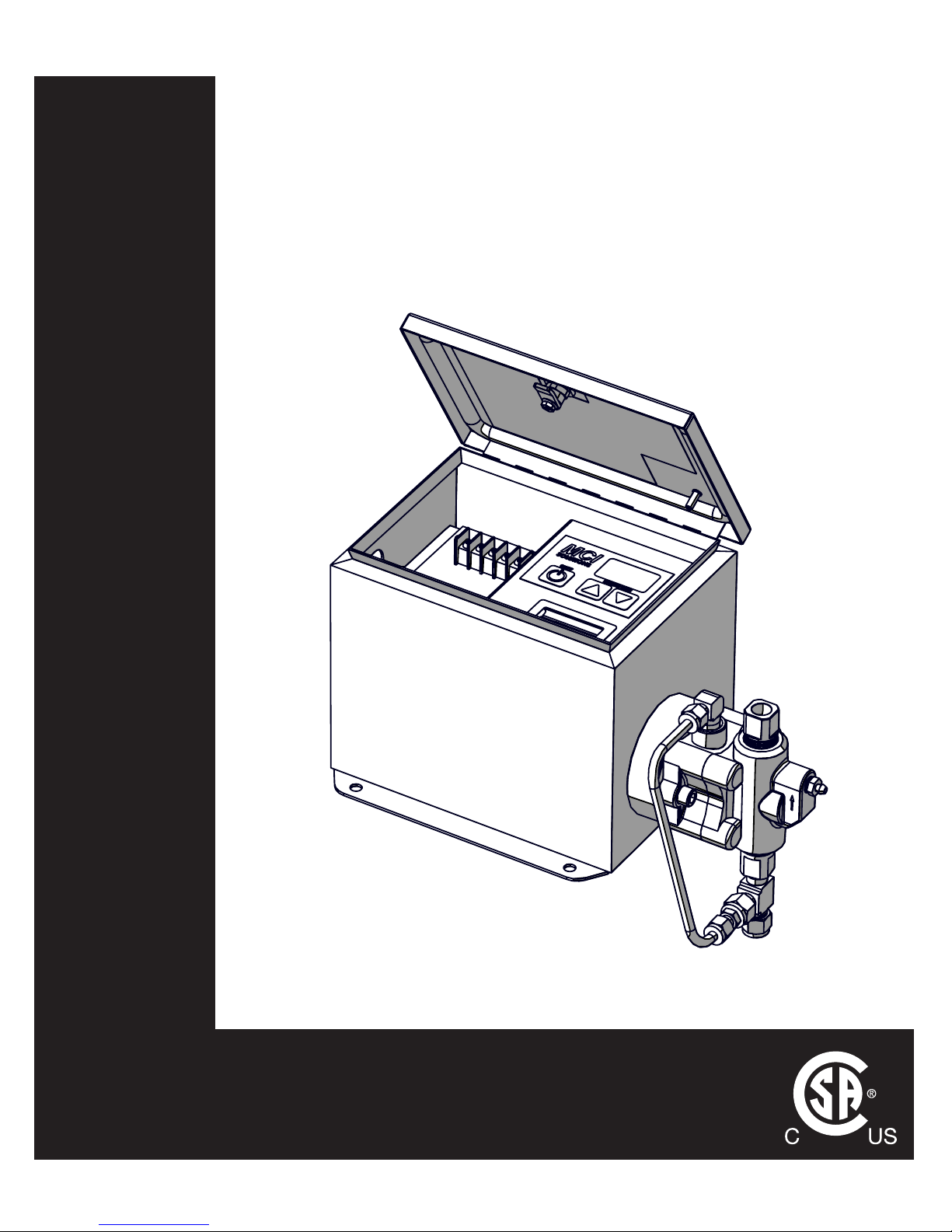
OPERATIONS MANUAL
MODEL C1 ELECTRIC CHEMICAL
INJECTION SYSTEM
C SERIES

GENERAL SAFETY
ii
www.mcisolutions.ca
Table Of Contents
General Safety 1
Symbol Usage . . . . . . . . . . . . . . . . . . . . . . . . . . . . . . . . . . . . . . . . . . . . . . . . 1
Proper Use . . . . . . . . . . . . . . . . . . . . . . . . . . . . . . . . . . . . . . . . . . . . . . . . . .2
Sources of Danger . . . . . . . . . . . . . . . . . . . . . . . . . . . . . . . . . . . . . . . . . . . . .2
Authorized Operators . . . . . . . . . . . . . . . . . . . . . . . . . . . . . . . . . . . . . . . . . . . 3
Personal Protective Equipment . . . . . . . . . . . . . . . . . . . . . . . . . . . . . . . . . . . . . 4
In Case of Emergency . . . . . . . . . . . . . . . . . . . . . . . . . . . . . . . . . . . . . . . . . . .4
System Specications 5
Electric Drive Dimensions . . . . . . . . . . . . . . . . . . . . . . . . . . . . . . . . . . . . . . . . . 5
Mounting Dimensions . . . . . . . . . . . . . . . . . . . . . . . . . . . . . . . . . . . . . . . . . . . 5
Static Head Requirements . . . . . . . . . . . . . . . . . . . . . . . . . . . . . . . . . . . . . . . . 6
Electrical Specications . . . . . . . . . . . . . . . . . . . . . . . . . . . . . . . . . . . . . . . . . . 6
General Specications . . . . . . . . . . . . . . . . . . . . . . . . . . . . . . . . . . . . . . . . . . . 7
Output Performance . . . . . . . . . . . . . . . . . . . . . . . . . . . . . . . . . . . . . . . . . . . . 7
Installation 8
General . . . . . . . . . . . . . . . . . . . . . . . . . . . . . . . . . . . . . . . . . . . . . . . . . . . .8
Standard Package Contents . . . . . . . . . . . . . . . . . . . . . . . . . . . . . . . . . . . . . . .8
Plumbing Overview . . . . . . . . . . . . . . . . . . . . . . . . . . . . . . . . . . . . . . . . . . . .9
Power Supply . . . . . . . . . . . . . . . . . . . . . . . . . . . . . . . . . . . . . . . . . . . . . . . .12
System Startup . . . . . . . . . . . . . . . . . . . . . . . . . . . . . . . . . . . . . . . . . . . . . . .14
Operating Instructions 15
Controller Overview . . . . . . . . . . . . . . . . . . . . . . . . . . . . . . . . . . . . . . . . . . . . 15
Setting Flow Rate . . . . . . . . . . . . . . . . . . . . . . . . . . . . . . . . . . . . . . . . . . . . . . 16
Troubleshooting 18
Bill of Materials 21
Material Codes . . . . . . . . . . . . . . . . . . . . . . . . . . . . . . . . . . . . . . . . . . . . . . . . 21
General System Detail View . . . . . . . . . . . . . . . . . . . . . . . . . . . . . . . . . . . . . . .22
FMT Fluid End . . . . . . . . . . . . . . . . . . . . . . . . . . . . . . . . . . . . . . . . . . . . . . . . 23
Plunger Seals . . . . . . . . . . . . . . . . . . . . . . . . . . . . . . . . . . . . . . . . . . . . . . . . . 24
In-line Filter . . . . . . . . . . . . . . . . . . . . . . . . . . . . . . . . . . . . . . . . . . . . . . . . .25
Pressure Relief Valve . . . . . . . . . . . . . . . . . . . . . . . . . . . . . . . . . . . . . . . . . . . . 25
Maintenance 27
Preventative Maintenance Schedule . . . . . . . . . . . . . . . . . . . . . . . . . . . . . . . . . . 27
Lubrication Details . . . . . . . . . . . . . . . . . . . . . . . . . . . . . . . . . . . . . . . . . . . . . 28
Plunger Seal Maintenance Procedure . . . . . . . . . . . . . . . . . . . . . . . . . . . . . . . . . 28
Check Valve Maintenance . . . . . . . . . . . . . . . . . . . . . . . . . . . . . . . . . . . . . . . . . 35
Limited Warranty 38
Maintenance Log 39
1
www.mcisolutions.ca
The C1 Electric Chemical Injection System has been subjected to a safety test and quality acceptance inspection. Please ensure all safety instructions in this manual are clearly understood. Misuse or incorrect
operation of the System may cause serious injury or death
Only properly and trained personnel should be involved in the setting up, putting into service, inspecting, servicing and repairing of this equipment.
Read and understand all instructions. Failure to follow the Dangers,
Cautions and Warnings contained in this owners manual may result in electric
shock, re, serious bodily injury or death
CAUTION!
General Safety
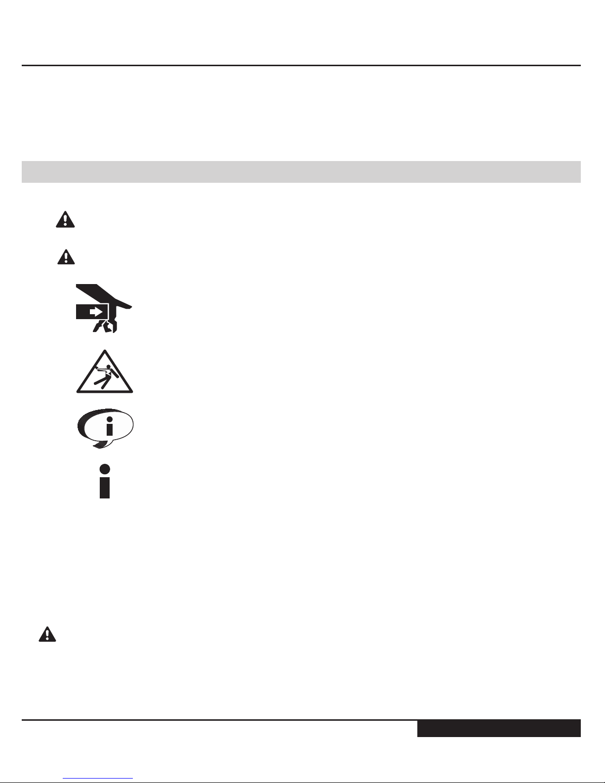
Symbol Usage
Designates an imminent danger. In case of non-observance of this information, death or severe injuries are an imminent risk
Designates possibility of a dangerous situation. In case of non-observance of this information, death or severe injuries can occur
Designates areas where the potential for severe crush injury exists.
These crush injuries can result in serious bodily injury
Electrical Shock Hazard Warning indicates a potential injury hazard that
can result in serious bodily injury or death
Designates important user tips and other useful information
Designates important installation information that if not followed could
cause System failure
DANGER!
CAUTION!
GENERAL SAFETY
2
www.mcisolutions.ca
NOTICE TO INSTALLER: This manual must be left with the owner/operator of the System and kept
for future reference
Proper Use
This System uses a reciprocating positive displacement pump. It serves the purpose of conveying and
circulating liquids. The System and these operating instructions are intended for commercial use exclusively
Severe skin injury can result from dangerous media used with this System.
(i.e. Aggressive, toxic and caustic media)
Unsuitable media can damage the pump and then escape into the surrounding area
If you intend to use dangerous media, the materials used for the pump parts
must be designed and compatible for this use
ANY form of liability on the part of the manufacturer shall be null and
void if the System has been modied by others without authorization
from MCI
When replacing parts in the System, use only spare parts approved by MCI. (Refer to the Bill of Materials
section in this manual for more information )
Always Disconnect power to the System before performing ANY maintenance
or repair activities
Sources of Danger
The System has been manufactured in compliance with CSA standards and complies with all applicable
safety requirements
Although most safety risks have been reduced through design and construction measures, residual risks
(i.e. explosive atmospheres, electrical, mechanical or thermal) cannot be excluded entirely during either
transport, maintenance and repair work, or regular operation
CAUTION!
CAUTION!
DANGER!
3
www.mcisolutions.ca
Authorized Operators
Only persons who have been properly authorized and trained by MCI or its authorized agent may work
on or with this equipment
The owner must:
■ Clearly dene and ensure the observance of the responsibilities for all tasks performed in con-
nection with the System
■ Make this manual accessible to all operations sta
■ Make sure operations have read and understood all operating instruction
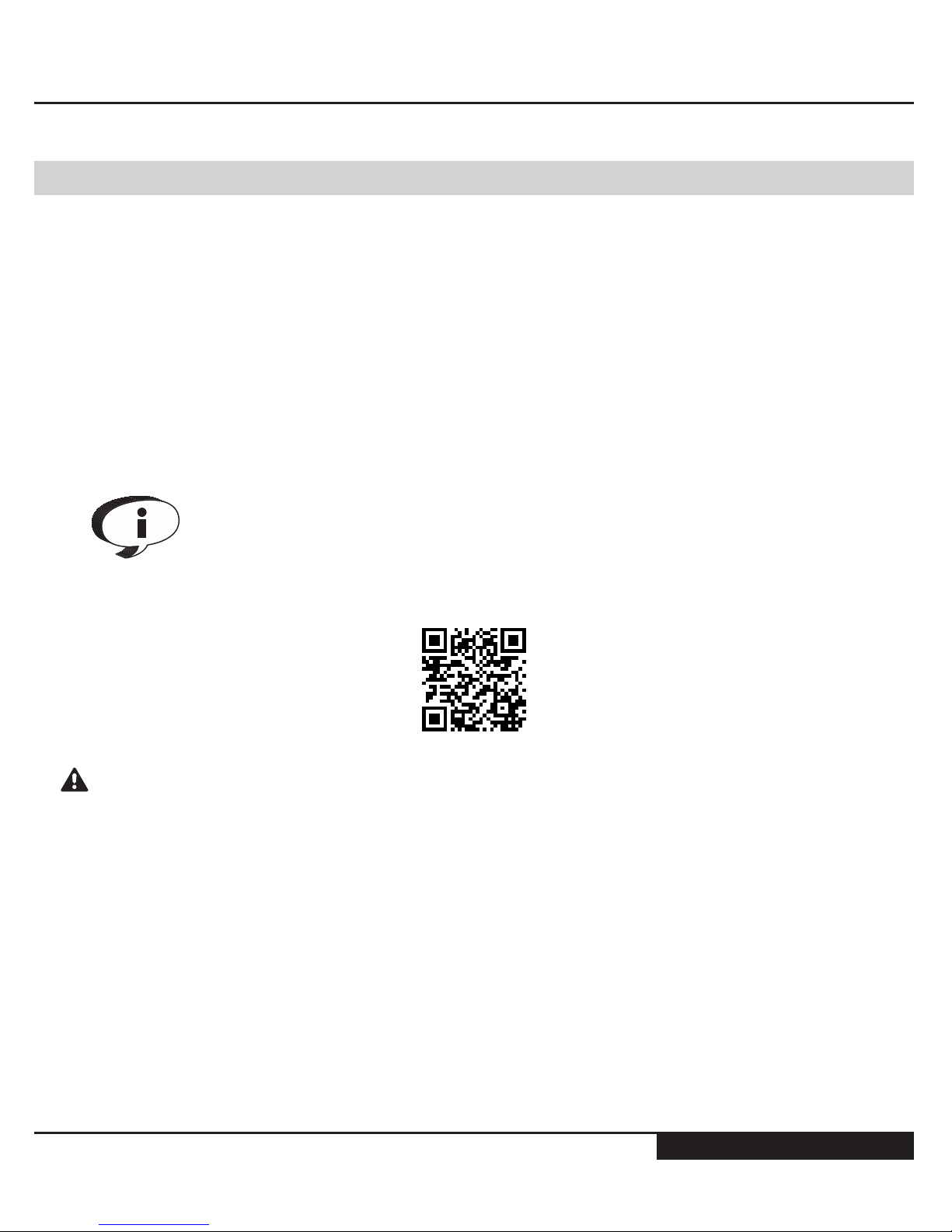
For Extra copies of this manual or for more information please visit us online
at: www.mcisolutions.ca
Or, Scan the following QR code with your smart phone for a direct link to
digital copies of all MCI Operation Manauls:
Maintenance, upkeep and electrical tasks should only be performed by
technically competent, trained and/or qualied personnel
Technically competent people, trained and qualied personnel are dened as individuals who:
■ Possess sucient knowledge in a specic eld based on their specialized training and experi-
ence; and
■ Are familiar with all applicable work safety and accident prevention regulations (i.e. lock-out or
tag-out safety procedures)
CAUTION!

GENERAL SAFETY
4
www.mcisolutions.ca
Personal Protective Equipment
Wear appropriate protective equipment especially when performing any
maintenance, inspection or cleaning task on the System
Oils, Lubricants and cleaning agents can cause skin reactions and irritation.
Avoid skin contact with all chemical used in connection with the System
In Case of Emergency
In case of Emergency originating from the System or from conditions in the surrounding area, the System must be switched o immediately
The System cannot be put back into operation until the emergency has been identied and corrected.
Ensure corrective actions are taken to prevent future occurrence
In case of res, use only suitable re-extinguishing agents
If the instructions in this manual are not adhered to or are inadequately
adhered to , the warranty shall become null and void and the CSA declaration of conformity shall immediately cease to be valid
MCI makes no other warranty, including without limitation, any warranties or merchantability or of tness
for a particular purpose, whether express or implied. MCI will not be liable under any circumstances
whatsoever to the purchaser for any damages relating to loss of production, loss of product, environment
damage, or any incidental, consequential, special or punitive damages regardless of whether arising in
contract, strict liability, other tort or otherwise. The exclusive remedy of the purchaser for any and all
losses, injuries or damages resulting from the sale, use or handling of any product whether in contract,
warranty tort, negligence, strict liability or otherwise, will not exceed the purchase price paid, or at MCI’s
sole election, the repair or replacement of the product
CAUTION!
CAUTION!
5
www.mcisolutions.ca
System Specications
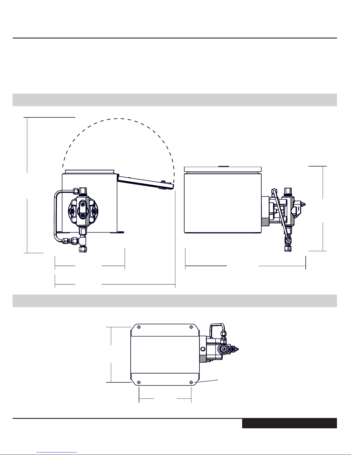
Electric Drive Dimensions
335 mm
(13.2 in)
370 mm
(14.5 in)
190 mm
(7.5 in)
330 mm
(13.0 in)
234 mm
(9.2 in)
LID CLOSED
Mounting Dimensions
173 mm
(6.8 in)
C/L TO C/L
163 mm
(6.4 in)
C/L TO C/L
7.9 mm
(0.313 in)
Diam. (x4)

GENERAL SAFETY
6
www.mcisolutions.ca
Static Head Requirements
MINIMUM (CL TO CL)
305 mm
(12.0 in)
Electrical Specications
Electrical Rating 24V DC
Classication CSA CLASS 1 DIVISION 2
Enclosure Rating Nema 3R
Temperature Code T4A
Motor Type 4 Pole Stepper Motor, 1.8 Degree Step
Inrush Current 950 (mA)
Avg. Power Consumption 450 (mA) MAX
Reverse Polarity Protection Standard
Analog Input [4-20 mA] Optional Upgrade [Innite Scale adjustments and
remote On/O capability]
Integrated Low Voltage Disconnect Standard [custoM set points AvAilAble]
7
www.mcisolutions.ca
General Specications
N-seal Leak Containment Adaptor Standard
Variable Speed Controller Electronic/ MOSFET
Electro-mechanical contactors / Relays N/A
Electro-mechanical Timers N/A
Dip Switch N/A
Fluid End Carbon Steel [316L S.S. Upgrade available]
Fluid End Suction and Discharge Seals OMX Fluoroelastomer®
Secondary Containment Static Seals Teon®
Seal Kit Dynamic Seals UHMW Polyethylene c/w Stainless Steel spring.
Plunger Material Tungsten Carbide
Operating Temperature -40 to +40 [oC]
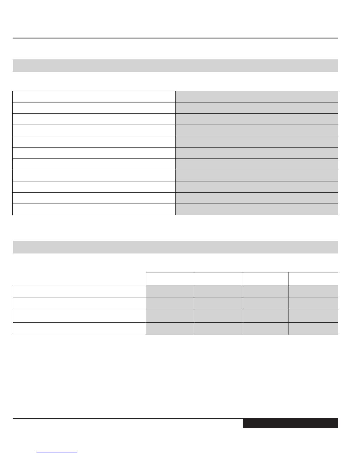
Output Performance
1/4" Plunger 3/8" Plunger 1/2" Plunger 11/16" Plunger
Maximum Displacement Pressure [Psi] 3000 1500 750 400
Maximum Displacment Pressure [kPa] 20684 10342 5171 2758
Maximum Output Volume [Litres/day] 12 29 52 104
Minimum Output Volume [Litres/Day] 0.12 0.26 0.46 0.86
GENERAL SAFETY
8
www.mcisolutions.ca
Installation
General
Congratulations. You have chosen the nest, most accurate electrically powered chemical injection System available. Before Installation, please inspect the pump carefully for any possible in-transit damage. If the pump appears damaged, call your local distributor or call MCI customer service direct at
+1.888.263.4565
Please ensure you have fully read and understood the general safety
section of this manual before proceeding with the System installation
The System is CSA approved for use in Class 1 Division 2 areas. It is the
responsibility of the owner to determine the classication of the area
where the System is to be installed
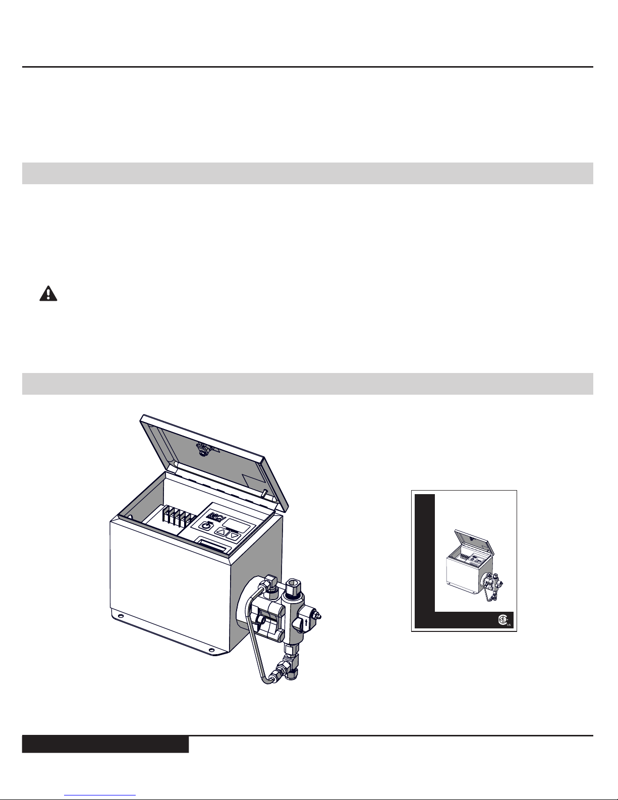
Standard Package Contents
C1 Electric Drive (x1)
Manual (x1)
OPERATIONS MANUAL
MODEL C1 ELECTRIC CHEMICAL
INJECTION SYSTEM
C SERIES
www.mcisolutions.ca
CAUTION!

9
www.mcisolutions.ca
The System is to be mounted securely in a safe location that satises the classication requirements.
The Systems Fluid End (Pump) must be oriented in a vertical position for proper check valve operation
Allow a minimum distance of 12 in. from the center line of the pump head to the lowest point on the
chemical storage container bulkhead to ensure adequate [positive] static head pressure is available. The
System relies on a positive suction pressure to run correctly [grAphic eXplAnAtion shown on pAge 6]
The membrane switch panel is covered with a clear plastic lm, remove prior to operating the System
Plumbing Overview
Only properly qualied and trained personnel should be involved in the
setting up , putting into service, inspecting, servicing and repairing of the
plumbing for the uid end
Ensure all National, Provincial/State and local codes are followed when plumbing equipment. Failure to follow these codes can result in serious bodily injury
or death
The following plumbing suggestions are examples of typical installations only and may not be the best
suited method for your custom installation
Ensure all process valves are closed prior to disconnecting or re-installing any chemical injection System
To avoid over-pressuring chemical discharge lines MCI requires placing a properly tested and calibrated
Pressure Relief valve (PRV) between the discharge port of the uid end and the process injection point.
The set point must not exceed the pumps maximum discharge pressure [MAXiMuM dischArge pressures cAn be
found in the 'systeM specificAtions' section under 'output perforMAnce']
Failure to add a CERTIFIED and CALIBRATED Pressure Relief Valve (PRV)
to the System is inherently unsafe. It can cause catastrophic System
damage and voids all System warranty. MCI is not responsible for any
damage caused by exceeding maximum System pressure. MCI oers
complete PRV solutions for all Systems. Please contact customer service
for latest pricing and availability: +1.888.263.4565
CAUTION!
GENERAL SAFETY
10
www.mcisolutions.ca
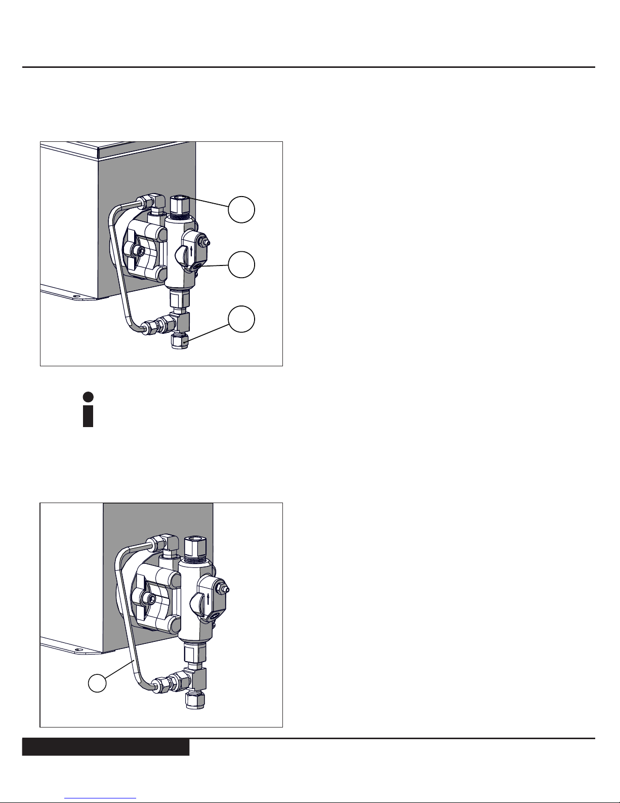
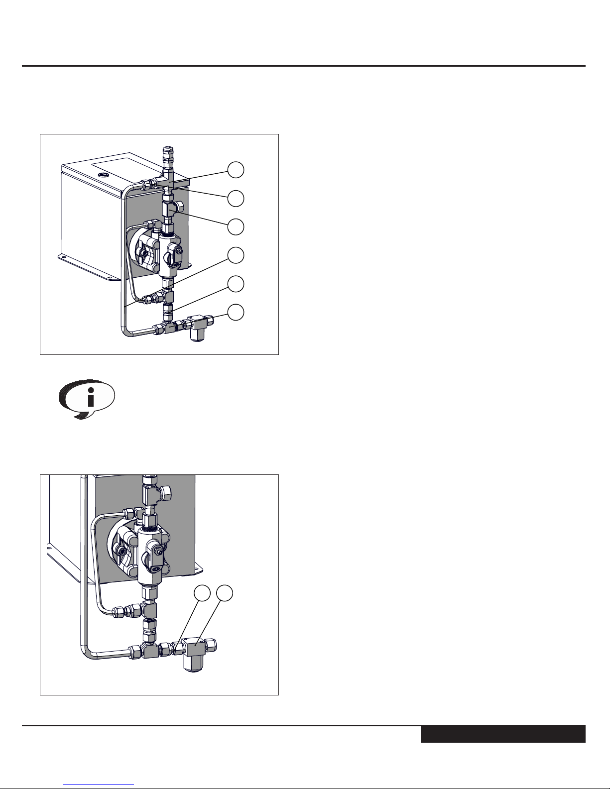
Standard Connection Points
Removing foreign debris from suction lines and chemical storage containers
will greatly extend the life of all dynamic seals used in the System. It is highly
recommended to use a pre-suction in-line lter on all Systems. MCI oers
in-line lter kits for all pump models. Please contact customer service for the
latest pricing and availability: +1.888.263.4565
Secondary Containment Line
1. Fluid End Discharge Point - 1/4” Fem. NPT
2. Pressure Transducer Port - 1/8" NPT
3. Fluid End Suction Point - 3/8” Tube
3
1
2
1. Secondary containment line - 1/4” Tube
1
11
www.mcisolutions.ca
Pressure Relief Valve Tie-In [TYPICAL ARRANGEMENT SHOWN]
Pressure relief valve kits are available direct from MCI. Kits include all tubing
[where applicable] and ttings required to complete the installation. Contact
customer service for more information: +1.888.263.4565
Suggested in-Line Filter [TYPICAL ARRANGEMENT SHOWN]
1. Pressure Relief Valve
2. Male Connector - 1/4” NPT x 3/8” Tube
3. Run Tee - 1/4” NPT [Main Discharge Point]
4. Stainless Steel Tubing [.035] - 3/8”
5. Tube Connector - 3/8”
6. Union Tee - 3/8”
6
5
4
3
1
2
1. In-line lter - 440 Micron
2. Tube connector - 3/8”
12
GENERAL SAFETY
12
www.mcisolutions.ca
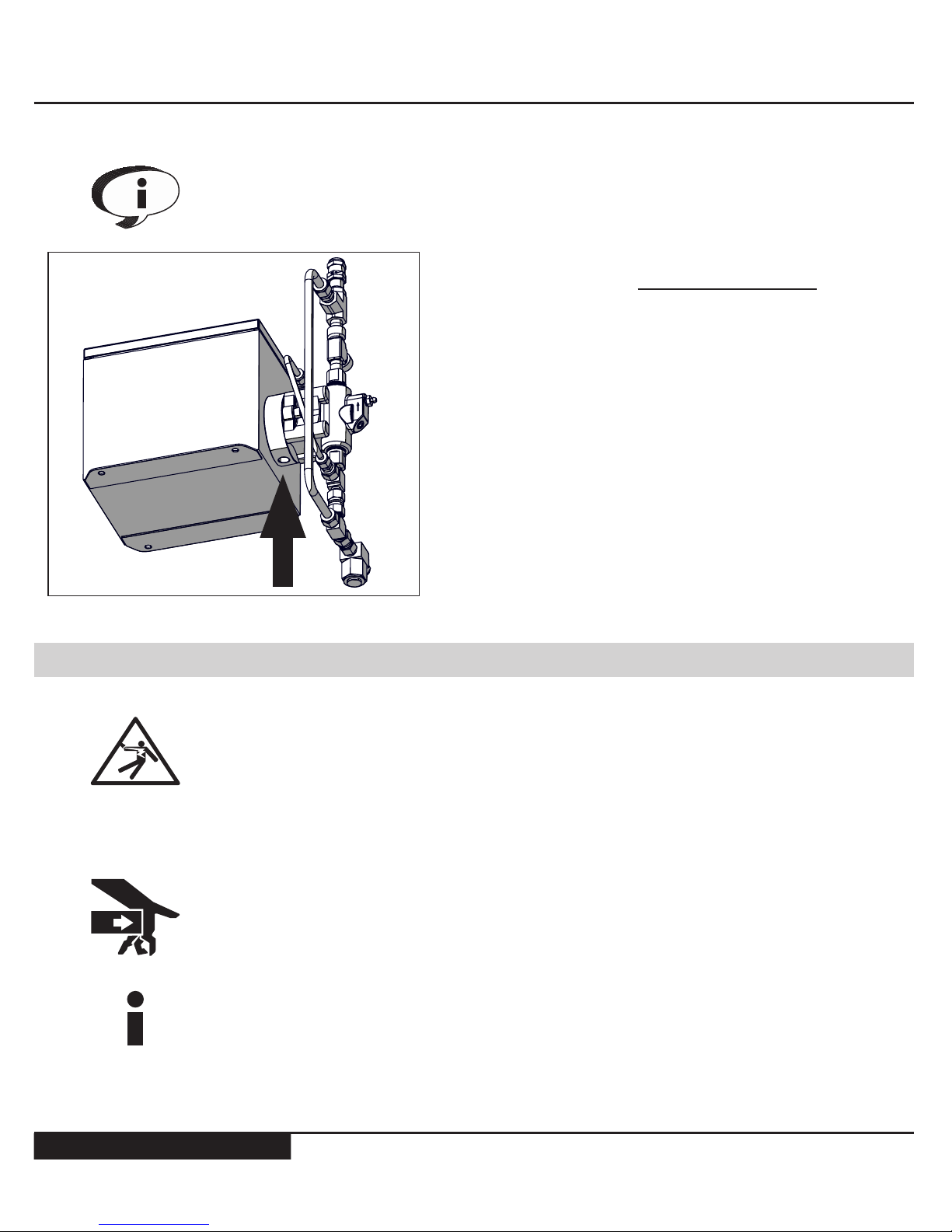
In-line lter assemblies are available direct from MCI. Kits include all tubing
[where applicable] and ttings required to complete the installation. Contact
customer service for more information: +1.888.263.4565
The 1/4” NPT drain port shown [Arrow] is a general
System drain port [DO NOT PLUG OFF] This port
must remain open or plumbed to a designated
containment area
Without routine maintenance it is possible for seal
bypass from the low pressure side to exit this port.
Ensure proper containment areas are in place and
suggested routine seal maintenance procedures
are followed to prevent spills
Power Supply
When wiring the System follow cable orientation labels found on the inside of
the enclosure lid. Failure to orientate wiring properly may result in damage to
the on-board electronics and could cause serious bodily injury or death
To protect the System and associated components the pump box must be
connected to ground. All electrical connections must satisfy National, Provincial/State and local electrical codes
SYSTEM CAN START AUTOMATICALLY - Before connecting power to the
control board ensure that you and all tools used in setup are clear of moving
parts, serious bodily injuries can occur
When connecting cables to the control module ensure keyed connections
are tight. Loose connections can cause arcing and erosion which destroy the
integrity of the connections

13
www.mcisolutions.ca
Power Supply Requirement - 24 V DC
Power supply cannot exceed 28 V or damage to electrical components will
result
Power Supply Wiring
Do not connect or disconnect motor while the controller is powered or
damage to the controller can result
To ensure safe and proper System operation DO NOT exceed maximum
recommended injection pressures. Maximum System pressures are avail-
able under the 'systeM specificAtions' section of this manual
1. Wiring Terminal Block - #6-32 Screws
2. Knockout [To Accept 1/2" Liquidtight Conduit]
3. Programming Port
4. In-line fuse Holder*
* Accepts 0.25 x 1.25” fast acting 2.5A glass fuse
2
4
3
1
CAUTION!
CAUTION!

GENERAL SAFETY
14
www.mcisolutions.ca
System Startup
STEP 1
WIRING INTERFACE
Wire 24V DC power supply out to the main terminal block on the pumps front access panel, always
ensure wiring polarity is correct to prevent system damage. CAUTION: System will start automatically
Model C1 pumps are equipped with COLDStart technology. This technology ensures proper operation
during the winter months by temporarily increasing the motors supply current at startup. When the system is in COLD start mode 'UP' will appear on the digital display . The System will automatically revert to
normal operating conditions when its warm up routine is complete [~10 Minutes]
If the ambient temperature is warmer than -10O C the COLDStart routine is not required. To bypass the
routine early, press the 'UP' or 'DOWN' arrow button once to resume normal operation
STEP 2
If desired 'Strokes Per Minute' [SPM] setting is known adjust desired pump rate by pressing the UP/
DOWN stroke rate keys on the control module until desired SPM rate is displayed
If desired stroke rate is not known please refer to the next section in this manual 'Operating Instructions'
for a complete set of instructions

15
www.mcisolutions.ca
Operating Instructions
Controller Overview
Ensure you have fully read and understood all sections of this manual before
operating this equipment
MCI’s user interface has been designed to simplify the process of setting and adjusting the chemical
injection drive. This section has been included to explain how to use the 3 button controller interface
CAUTION!
ON / OFF SwitchCycles power to
pump
Integrated RED LED - (Blinks
when power is supplied to the
board and the pump is in the
OFF position)
Digital Stroke Rate Display Press the UP/DOWN arrow to
activate display when the pump
is cycling
[strokes per Minute]
UP / DOWN Arrows - Used to
adjust the pumps strokes per
minute rate setting

GENERAL SAFETY
16
www.mcisolutions.ca
Setting Flow Rate
STEP 1
Determine Systems plunger size *[1/4”, 3/8”, 1/2” or 11/16” Diameter]
*plunger id lAbels Are included with Mci systeMs to help quickly identify plunger size. the decAl cAn be found on
the front top right hAnd corner of your electric drive enclosure
STEP 2
When safe to do so open the enclosure access panel and locate the pump rate chart found inside the
pump enclosure lid [shown below]
Pump Rate
Chart
PUMP RATE CHART
PLUNGER SIZE (DIAMETER)
STROKES
PER
MINUTE
1/4" 3/8" 1/2" 11/16"
LITRES PER DAY (OUTPUT)
0.1 0.12 0.26 0.46 0.86
0.2 0.23 0.44 0.79 1.49
0.3 0.35 0.66 1.20 2.26
0.4 0.46 0.85 1.60 3.02
0.5 0.58 1.10 2.00 3.78
1.0 1.0 2.2 3.9 7.37
1.5 1.4 3.3 6.0 11.3
2.0 2.0 4.4 7.9 14.9
2.5 2.5 5.5 9.9 18.7
3.0 2.0 6.6 11.8 22.3
3.5 3.4 7.7 13.8 26.0
4.0 3.9 8.8 15.7 29.7
4.5 4.4 9.9 17.7 33.4
5 4.9 11.1 19.7 37.2
5.5 5.4 12.2 21.7 41.0
6.0 6.0 13.3 23.6 44.6
6.5 6.4 14.4 25.6 48.4
7.0 6.9 15.5 27.5 52
7.5 7.4 16.7 29.6 55.9
8.0 7.9 17.7 31.5 59.5
8.5 8.3 18.9 33.5 63.3
9.0 8.8 19.9 35.4 66.9
9.5 9.4 21.1 37.4 70.7
10.0 9.7 22.2 39.4 74.5
11.0 10.8 24.4 43.4 82.0
12.0 11.8 26.6 47.3 89.4
13.0 12.8 28.8 51.3 96.9
14.0 13.8 31.0 55.2
104.3
15.0 14.8 33.2 59.1
111.7
(CONTINUED)
DO NOT EXCEED THE
SYSTEMS MAXIMUM
DISCHARGE PRESSURE
AS SHOWN BELOW
PLUNGER
SIZE
(DIAMETER)
MAXIMUM
PRESSURE
(PSIG)
1/4" 3000
3/8" 1500
1/2" 750
11/16" 400
STEP 3
Review pump rate chart and ensure the intended discharge pressure is within the maximum discharge
pressure rating of the System. do not exceed maximum operating pressure or system damage can occur
PUMP RATE CHART
PLUNGER SIZE (DIAMETER)
STROKES
PER
MINUTE
1/4" 3/8" 1/2" 11/16"
LITRES PER DAY (OUTPUT)
0.1 0.12 0.26 0.46 0.86
0.2 0.23 0.44 0.79 1.49
0.3 0.35 0.66 1.20 2.26
0.4 0.46 0.85 1.60 3.02
0.5 0.58 1.10 2.00 3.78
1.0 1.0 2.2 3.9 7.37
1.5 1.4 3.3 6.0 11.3
2.0 2.0 4.4 7.9 14.9
2.5 2.5 5.5 9.9 18.7
3.0 2.0 6.6 11.8 22.3
3.5 3.4 7.7 13.8 26.0
4.0 3.9 8.8 15.7 29.7
4.5 4.4 9.9 17.7 33.4
5 4.9 11.1 19.7 37.2
5.5 5.4 12.2 21.7 41.0
6.0 6.0 13.3 23.6 44.6
6.5 6.4 14.4 25.6 48.4
7.0 6.9 15.5 27.5 52
7.5 7.4 16.7 29.6 55.9
8.0 7.9 17.7 31.5 59.5
8.5 8.3 18.9 33.5 63.3
9.0 8.8 19.9 35.4 66.9
9.5 9.4 21.1 37.4 70.7
10.0 9.7 22.2 39.4 74.5
11.0 10.8 24.4 43.4 82.0
12.0 11.8 26.6 47.3 89.4
13.0 12.8 28.8 51.3 96.9
14.0 13.8 31.0 55.2
104.3
15.0 14.8 33.2 59.1
111.7
(CONTINUED)
DO NOT EXCEED THE
SYSTEMS MAXIMUM
DISCHARGE PRESSURE
AS SHOWN BELOW
PLUNGER
SIZE
(DIAMETER)
MAXIMUM
PRESSURE
(PSIG)
1/4" 3000
3/8" 1500
1/2" 750
11/16" 400
PLUNGER
SIZE
(DIAMETER)
MAXIMUM
PRESSURE
(PSIG)
1/4" 3000
3/8" 1500
1/2" 750
11/16" 400
Example: 1/4” Plunger has a Maximum discharge pressure of 3000 psig

17
www.mcisolutions.ca
STEP 4
Select desired output volume from appropriate 'Litres Per Day' column for your specied plunger size.
Determine the 'Strokes Per Minute' setting for your chosen output volume by looking to the far left of
the selected volume row. [see example below]
Example: To achieve 2.0 Litre Per Day output volume with
a 1/2" Plunger the strokes per minute setting is 0.5
(1/4”) (3/8”) (1/2”)
PUMP RATE CHART
PLUNGER SIZE (DIAMETER)
STROKES
PER
MINUTE
1/4" 3/8" 1/2" 11/16"
LITRES PER DAY (OUTPUT)
0.1 0.12 0.26 0.46 0.86
0.2 0.23 0.44 0.79 1.49
0.3 0.35 0.66 1.20 2.26
0.4 0.46 0.85 1.60 3.02
0.5 0.58 1.10 2.00 3.78
6.0 6.0 13.3 23.6 44.6
6.5 6.4 14.4 25.6 48.4
7.0 6.9 15.5 27.5 52
7.5 7.4 16.7 29.6 55.9
8.0 7.9 17.7 31.5 59.5
(CONTINUED)
DO NOT EXCEED THE
SYSTEMS MAXIMUM
DISCHARGE PRESSURE
AS SHOWN BELOW
PLUNGER
SIZE
(DIAMETER)
MAXIMUM
PRESSURE
(PSIG)
1/4" 3000
3/8" 1500
1/2" 750
PUMP RATE CHART
PLUNGER SIZE (DIAMETER)
STROKES
PER
MINUTE
1/4" 3/8" 1/2" 11/16"
LITRES PER DAY (OUTPUT)
0.1 0.12 0.26 0.46 0.86
0.2 0.23 0.44 0.79 1.49
0.3 0.35 0.66 1.20 2.26
0.4 0.46 0.85 1.60 3.02
0.5 0.58 1.10 2.00 3.78
6.0 6.0 13.3 23.6 44.6
6.5 6.4 14.4 25.6 48.4
7.0 6.9 15.5 27.5 52
7.5 7.4 16.7 29.6 55.9
8.0 7.9 17.7 31.5 59.5
(CONTINUED)
LITRES PER DAY
STROKES
PER
MINUTE
(11/16”)
STEP 5
Finally, set your desired 'Strokes Per Minute' rate on the pump controller by pressing the UP/DOWN
stroke rate arrows until the desired setting is displayed
Due to System design variances such as instrumentation and media viscosities it is important to always conrm injection rates using a calibrated tank
gauge. Adjust rate settings as required
....

GENERAL SAFETY
18
www.mcisolutions.ca
Troubleshooting
Symptom Potential Cause(s) Recommendation(s)
Electric drive does
not cycle when
powered
Pump controller is o Press the On/O button to cycle power
Loose or damaged power supply wiring Conrm all connections are securely fastened and that no mechanical
damage to wiring has occurred
Re-connect wiring and thread together tightly
Wiring polarity reversed on main power
supply cable
[see 'instAllAtion' section of this MAnuAl for
wiring diAgrAM]
Reverse wiring if found to be incorrect.
[Warning: Control module boards manufactured prior to 2010 may not
be equipped with reverse polarity protection and if powered in a reverse
condition will require replacement]
Damaged fuse Remove fuse holder cap and inspect fuse for damage. Replace if required
[0.25 x 1.25” - 2.5A]
Low voltage condition *
*if your systeM is equipped with the integrAted
low voltAge disconnect [lvd] the screen will
displAy 'pp' indicAting A power probleM [low
voltAge condition]
Conrm 24V DC power supply is available to the control module with a
volt meter. Replace or repair power supply as required
If the System is running o a DC battery bank it is recommended to disconnect the charging source [i.e. solAr pAnels] before checking line voltage
to ensure accurate results
Damaged charge regulator Conrm charge regulator is outputting 24-28V. If your charge regulator
is equipped with a low voltage disconnect make sure to test its functionality and set points
Controller display
does not respond to
pressing on/o or
stroke rate buttons,
but the drive is
cycling normally
Pump is in analog mode [4-20 mA input] If your pump is equipped with the optional 4-20 mA analog input it will
override manual entries when in remote mode. Disconnecting the 4-20
mA input cable will resume normal manual operation
Pump is chattering
or not stroking the
full stroke [1 inch]
note: during norMAl
wArM up routine cycles
['up' shown on displAy]
the puMp will cycle
hAlf strokes And does
not indicAte A probleM
with the drive
Low voltage condition Conrm 24V power supply is available to the control module with a volt
meter
If the System is running o a DC battery bank it is recommended to dis-
connect the charging source [i.e. solAr pAnels] before checking line voltage
to ensure accurate results
This condition can cause damage to the Systems drive if left for extended periods. If after identifying and correcting a voltage problem and the drive is still found to chatter it is recommended to send
the System in for inspection as motor bearings may be damaged
Discharge Isolation valve(s) closed If any valves are found to be closed and if safe to do so, open valves
Original controller replaced MCI oers many drive options that require specic controllers. Before
installing a new pump controller please contact MCI customer service:
+1.250.888.4565 to conrm compatibility. Please provide the Systems
model and serial number to conrm compatibility
Pumps maximum rated discharge pressure has been exceeded
Please conrm your pumps maximum output pressure rating. This can
be found under the 'Specications' section of this manual. It is very important this pressure not be exceeded. It is unsafe and will cause premature System failure.
Damaged Control Module Contact customer service for repair options +1.250.888.4565

19
www.mcisolutions.ca
Symptom Potential Cause(s) Recommendation(s)
Pump cycles correctly but Chemical
does not discharge
at the correct rate
Pump may have lost prime/become 'Air
locked'
With the pump cycling, open the priming screw to release any trapped
air in the pump chamber. When chemical ows smoothly air has been
displaced. It is recommended to repeat this procedure to be sure all
trapped air has been evacuated from the System
Direct all chemical to a contained area to prevent spills when priming pump
Suction check valve clogged with debris Close suction isolation valves. Disconnect suction plumbing and remove
the suction check bushing. Inspect check valve O-ring and seat for debris. Clean and/or replace as required [o-ring size -012]
If the O-ring appears pitted, deformed or swollen it is recommended
to conrm your elastomers compatibility with media being injected.
Check Valve bodies do not need replacement when failing to seat.
Rebuild seal kits are available from MCI or your authorized pump distributor. Please contact MCI customer service for more information:
+1.250.888.4565
Low chemical Inventory If inventory is empty, rell supply
Running the pump dry may allow air to enter the System. When relling your chemical supply it is always recommended to prime the
pump head to evacuate air from System
Suction side isolation valve closed Isolation valves are typically found immediately exiting the chemical
tank bulkhead. Conrm all valves are in the open position
Chemical obstructed from entering the
pump. No chemical ow through primer
port when opened.
Plumbing upstream of the System may have blockages preventing
chemical from entering the uid end. Check the following:
1. A common example is a plugged in-line chemical lter, if found to
be the cause clean or replace the existing chemical lter
2. If the pump has been decommissioned for a period of time it is possible for the suction check ball to stick to its O-ring seat. To repair
dislodge the ball from the bottom side of the suction bushing. [It
is not required to remove the suction seat to perform this task]
Low Pressure
Dynamic seal
leaking through
drain port
Seals are worn/Damaged Order replacement seal kit and replace.
Although spring energized seals do not require any adjustment
throughout the life expectancy of the seal, they do have a life span
Due to System contaminants or abrasive qualities of certain chemicals it is dicult to predict seal life expectancy for all applications.
MCI recommends a semi-annual seal cartridge change to reduce the
risk of bypassed chemical.
It is possible for older chemical storage tanks to become contaminated
with debris over time. This can greatly reduce the life expectancy of the
seals and also aect check valve performance.
MCI oers high performance in-line chemical lters to greatly reduce the likelihood of this occurring. Please contact MCI customer
service for more information: +1.250.888.4565
LEAK AREA

GENERAL SAFETY
20
www.mcisolutions.ca
Symptom Potential Cause(s) Recommendation(s)
Static seal Leak
between pump
halves
Damaged Teon® O-ring Inspect O-ring seal faces for damage and replace O-ring as required
MCI chemical injection Systems are designed to be simple to operate and easy to repair. The best way to
ensure reliable and ecient service is to have your pump repaired at the factory. If non-factory repairs
are to be carried out please read and understand all maintenance procedures found under the 'Maintenance' section of this manual
If you are experiencing an operating problem not listed above, or if none of the troubleshooting actions have corrected your operating problem, please contact your authorized MCI reseller or call MCI
customer service: 1.888.263.4565
Exchange programs are also available through MCI. Minimize your downtime and labor by swapping
out a rebuilt pump rather than having to troubleshoot, order parts, uninstall and repair your pump.
Eliminate the guesswork, and get your System back to work quickly, at a cost that makes your decision
easy. Please contact customer service for more information: 1.888.263.4565
LEAK AREA

21
www.mcisolutions.ca
Bill of Materials
Material Codes
The following pages include multiple System views with part numbers and material codes to assist in
identifying parts in the System’s assembly
If additional information is required please contact customer service: +1.250.888.4565 When con-
tacting customer service it is helpful if you have the System serial number available to ensure
proper replacement parts are recommended
[Serial Numbers can be found on the front cover of the Systems enclosure]
MATERIAL CODES [Matl.]
316L STAINLESS STEEL SS
FLAME RETARDANT - THERMOPLASTIC TH
FLUOROELASTOMER FE
LOW CARBON STEEL CS
TEFLON® TE
TUNGSTEN CARBIDE - SOLID TC
ULTRA HIGH MOLECULAR WEIGHT POLYETHYLENE - UHMWPE UH
ZINC PLATED CARBON STEEL ZP

GENERAL SAFETY
22
www.mcisolutions.ca
General System Detail View
1
2
10
4
3
5
9
6
8
7
11
Component
Qty.
Matl.
Fluid End Plunger Size
All sizes 1/4" 3/8" 1/2" 11/16"
1 FUSE HOLDER BODY AND CAP 1 TH U36 -- -- -- --
2 FUSE [2.5A] 1 -- P07 -- -- -- --
3 OFFSET DISTANCE PIECE 1 ZP T70 -- -- -- --
4 O-RING - TEFLON (-031) 1 TE S49 -- -- -- --
5 fMt fluid end
AsseMbly (COMPLETE)
cArbon steel
1
CS --
FMT-C1-
CS-04
FMT-C1-
CS-06
FMT-C1-
CS-08
FMT-C1-
CS-11
stAinless steel SS --
FMT-C1-
SS-04
FMT-C1-
SS-06
FMT-C1-
SS-08
FMT-C1-
SS-11
6 5/16” SOCKET HEAD CAP SCREWS 2 ZP S44 -- -- -- --
7 SECONDARY CONTAINMENT LINE 1 SS P79 -- -- -- --
8 IN-LINE CHECK VALVE [1/4” TUBE X 1/4” NPT] 1 SS S64 -- -- -- --
9 1/4" REDUCER 1 SS Q58 -- -- -- --
10 3/8" RUN TEE 1 SS Q29 -- -- -- --
11 C1 PUMP ASSEMBLY [COMPLETE AS SHOWN] -- -- Z-PB-C1 -- -- -- --

23
www.mcisolutions.ca
FMT Fluid End
17
18
14
15
12
13
11
16
10
9
8
7654321
Component
Qty.
Matl.
Fluid End Plunger Size
All sizes 1/4" 3/8" 1/2" 11/16"
1 SEAL RETAINER SCREWS #10-32 2 SS S43
2 SEAL RETAINER 1 SS -- S93 S94 S95 S96
3 CAP SCREW - 1/4” 4 ZP S42 -- -- -- --
4 ROD END
cArbon steel
1
CS -- S24 S26 S28 S30
stAinless steel SS -- U22 U23 U24 U25
5 TEFLON® LOW PRESSURE O-RING [-029] 1 TE T87 -- -- -- --
6 SPRING ENERGIZED SEAL 2 UH -- S75 S76 S77 S78
7 TEFLON® HIGH PRESSURE O-RING 1 TE -- S45 S46 S47 S48
8 DISCHARGE CHECK VALVE BUSHING 1 SS S11 -- -- -- --
9 DISCHARGE BALL CHECK SPRING 1 SS R93 -- -- -- --
10 STAINLESS STEEL BALL - 0.375 DIAM. 2 SS R94 -- -- -- --
11 FLUOROELATOMER (OMX) O-RING 2 FE T82 -- -- -- --

GENERAL SAFETY
24
www.mcisolutions.ca
Component
Qty.
Matl.
Fluid End Plunger Size
All sizes 1/4" 3/8" 1/2" 11/16"
12 STAINLESS STEEL BALL - 0.250 1 SS R95 -- -- -- --
13 DISCHARGE CHECK VALVE SEAT 1 SS S32 -- -- -- --
14 PRIMING SCREW 1 SS S92 -- -- -- --
15 PIPE PLUG - 1/8” NPT 1 SS S73 -- -- -- --
16 BLIND END
CARBON STEEL
1
CS -- S25 S27 S29 S31
STAINLESS STEEL SS -- U26 U27 U28 U29
17 SUCTION CHECK VALVE SEAT 1 SS S12 -- -- -- --
18 TUNGSTEN CARBIDE PLUNGER 1 TC -- T58 T59 T60 T61
Plunger Seals
A
B
C
D
Component
Qty.
Matl.
Fluid End Plunger Size
All Models 1/4" 3/8" 1/2" 11/16"
A TEFLON® LOW PRESSURE O-RING [-029] 1 TE T87 -- -- -- --
B SPRING ENERGIZED SEAL 2 UH -- S75 S76 S77 S78
C TEFLON® HIGH PRESSURE O-RING 1 TE -- S45 S46 S47 S48
D FMT SEAL REBUILD KIT 1 -- --
FMT-
SEALKIT-04
FMT-
SEALKIT-06
FMT-
SEALKIT-08
FMT-
SEALKIT-11

25
www.mcisolutions.ca
In-line Filter
A B
Component
Qty.
Matl.
Fluid End Plunger Size
All Models 1/4" 3/8" 1/2" 11/16"
A TUBE CONNECTOR - 3/8” 1 SS S65 -- -- -- --
B IN-LINE STRAINER - 440 MICRON (3/8” TUBE) 1 SS R18 -- -- -- --
-- REPLACEMENT FILTER ELEMENT 1 SS R19 -- -- -- --
Pressure Relief Valve
5
4
3
2
1
6

GENERAL SAFETY
26
www.mcisolutions.ca
Component
Qty.
Matl.
Fluid End Plunger Size
All Models 1/4" 3/8" 1/2" 11/16"
1 MALE CONNECTOR - 1/4” NPT X 3/8” TUBE 1 SS P78 -- -- -- --
2 PRESSURE RELIEF VALVE 1 SS R04 -- -- -- --
3 RUN TEE - 1/4” NPT 1 SS S72 -- -- -- --
4 TUBE CONNECTOR - 3/8” 1 SS S65
-- -- -- --
5 UNION TEE - 3/8” 1 SS Q28
-- -- -- --
6 STAINLESS STEEL TUBING - 3/8” 1 SS P81
-- -- -- --
To ensure accurate and prompt parts delivery, the following information must
be provided when ordering components:
Serial Number - Located on the front cover of the Systems enclosure
Item Number - Found in Bill of Materials section of this manual

27
www.mcisolutions.ca
Maintenance
Preventative Maintenance Schedule
MCI series Systems are designed to provide trouble free service for many years with little inspection,
lubrication or other routine maintenance. However, like any other mechanical device proper maintenance can extend the life cycle of the System
The following schedule is intended as a guide only. Each application is dierent and should be evaluated and serviced according to its own custom maintenance schedule
SUGGESTED MAINTENANCE Monthly
SEMI
ANNUAL
ANNUAL
GENERAL SYSTEM CHECK
■ Inspect system for any leaks
■ Check valves seating correctly - use site glAss to confirM
■ Linear drive cycling normally
■ Conrm all mechanical fasteners are tight
■ If the system is charged o a 24V DC battery bank conrm batteries
and charging system are in good working order
•
INSPECT AND CLEAN IN-LINE FILTER ELEMENT
[If applicable]
•
REPLACE PLUNGER SEALS
See 'bill of materials' section for appropriate part numbers and refer to the
'maintenance' section for complete step-by-step instructions
•
LUBRICATE BALL-NUT / BALL-SCREW ASSEMBLY
Refer to the 'maintenance' section for complete step-by-step instructions.
Always use synthetic low temp grease that is rated for a minimum of -45 o c
•
INSPECT, CLEAN AND REPLACE CHECK VALVE SEALS AS
REQUIRED
Refer to ‘check valve maintenance’ section of this manual for complete
step-by-step instructions
•

GENERAL SAFETY
28
www.mcisolutions.ca
Lubrication Details
REMOVE PUMP TO ACCESS GREASE FITTING WHERE SHOWN ARROW
Grease Fitting Type: 1/4 inch Straight
Always disconnect power to the System before lubricating ballscrew assembly
To be used with Lincoln® pistol grip 18 in. grease gun [or equivAlent]. It is recommended to add 2 grams
of grease on an annual basis [This is equivalent to approximately 2.5 strokes on typical pistol/hand grip
grease guns, refer to your specic grease gun specications to conrm]
DO NOT OVER GREASE
Always use a SYNTHETIC low temperature grease that is rated for a minimum temperature of -45 oc
Plunger Seal Maintenance Procedure
Please ensure you have fully read and understood the general safety section
of this manual before proceeding with any maintenance procedures
Disconnect power to the System before proceeding with any maintenance
procedures
CAUTION!
CAUTION!

29
www.mcisolutions.ca
(1) Replacement seal kit required - See ‘Page 24’ for details
STEP 1
Disconnect Systems power supply. Close all suction and discharge isolation valves and remove both the suction and discharge chemical lines from uid end
To assist plunger removal in a later step it is highly
recommended to turn the system o while it is cycling to
the right so it is stopped in the required extended position
STEP 2
Disconnect secondary containment line [A] from uid end as
shown
A
STEP 3
Remove fastening screws [A] (x2) and uid end assembly [B]
as shown
B
A
STEP 4
Tilt and pull plunger [A] to remove* (As shown) Inspect for any
damages and clean thoroughly
*The System must be located in the extended position (All the
way to the right) to allow plunger removal [See Step 1]
STEP 5
Remove screws [A] (x4) and separate blind end [C] from rod
end [B] as shown
A B C
If internal porting of uid end is lled with debris it is highly
recommended to clean pump head thoroughly and perform
maintenance on check valves (See ‘Check Valve Maintenance’
section for more information)

GENERAL SAFETY
30
www.mcisolutions.ca
STEP 6
Remove high pressure dynamic seal [A] and static Teon® face
seal [B] from rod end and discard
USE CAUTION NOT TO SCRATCH SEAL FACES WHEN REMOVING SEALS
ALWAYS CLEAN SEAL FACES THOROUGHLY BEFORE REINSTALLING SEALS
B
A
STEP 7
Remove screws [A] (x2) and seal retainer [B] from rod end followed by the low pressure seal [C]. Clean Rod end thoroughly.
and inspect seal face for any scratching or pitting damage
CBA
STEP 8
Slide seal retainer [A] onto plunger [B] (Min. 2 inches) followed
by a NEW low pressure seal [C] as shown
B
A
C
THE SEAL
SPRING
MUST
FACE AWAY
FROM SEAL
RETAINER
[A] WHEN
LOADING
SEAL
SPRING
SEAL DIRECTION IS CRITICAL ENSURE SEAL SPRING
FACES AWAY FROM SEAL RETAINER WHEN INSTALLING
Slide plunger into rod end at least 1.5 inches [Fig. A]. Next,
press down on seal retainer to insert seal and retainer into
the rod end counter bore [Fig. B]. Finally, remove the plunger
while holding the seal retainer in place.
DO NOT GREASE PLUNGER
Fig. A

31
www.mcisolutions.ca
STEP 10
Install second seal in opposite side of rod end as shown. Ensure the seals spring faces out when installing
SEAL DIRECTION IS CRITICAL ENSURE SEAL SPRING
FACES AWAY FROM ROD END [OUT] WHEN INSTALLING
STEP 11
Remove high pressure static seal [A] from blind end [B] as
shown
Inspect and clean seal face before proceeding
B
A
PRESS SEAL
SLOWLY
Fig. B
PRESS SEAL AND SEAL
RETAINER INTO POSITION
SLOWLY
Fig. C
STEP 9
Install screws (x2) to lock seal retainer in position

GENERAL SAFETY
32
www.mcisolutions.ca
STEP 15
Re-install plunger [A] into plunger receiver [B] as shown
B
A
STEP 16
Align FMT uid end assembly with plunger and slowly slide
assembly up to distance piece [A]
STEP 12
Install NEW high pressure static seal [A] in blind end [B] as
shown
B
A
STEP 13
Install NEW low pressure static seal [A] in rod end [B] as shown
B
A
STEP 14
Mate Rod end to blind end and secure with mount screws (x4)
as shown
ENSURE ALL O-RINGS ARE PROPERLY SEATED BEFORE
FASTENING screws

33
www.mcisolutions.ca
STEP 17
Secure FMT uid end assembly to existing drive by installing
mount screws (x2) as shown
STEP 18
Re-connect secondary containment line [A] to uid end
assembly as shown
A
STEP 19
Connect all previously installed suction and discharge lines to
the uid end
CAUTION!
Only properly qualied and trained personnel should be involved
in the setting up, putting into service, inspecting and repairing of
this equipment
Ensure National, Provincial/State and local codes are followed
when plumbing equipment. Failure to follow these codes can result in serious bodily injury or death
Typical installation shown above. Please refer to the ‘Installation’ section of this manual for a complete item breakdown.

GENERAL SAFETY
34
www.mcisolutions.ca
Tie-In kit assemblies and in-line lter
assemblies are available direct from MCI.
Kits include all tubing [where applicable]
and ttings required to complete the installation. Contact customer service for more
information: +1.888.263.4565
STEP 20
When safe to do so, open all applicable suction and discharge
isolation valves
STEP 21
Re-connect 24V DC power supply to System.
CAUTION!
SYSTEM STARTS AUTOMATICALLY
Note: If your electric drive is equipped with
a warm up routine the display will read ‘UP’
The routine will automatically transition to
normal operation after a 10 minute cycle.
To bypass the warm up routine simply press
either the UP/DOWN arrow
STEP 22
Conrm the suction side of the pump is lled with uid by
opening the priming valve to check for uid. When the uid
ows smoothly through the primer (air displaced) close the
priming valve
The FMT Fluid End has been designed to redirect all lost uid
to a containment area when priming by attaching 1/4” tubing
to the primer valve before opening
Conrm injection rates using a calibrated tank/barrel gauge
to ensure the pump is injecting uid as expected
....

35
www.mcisolutions.ca
Check Valve Maintenance
Please ensure you have fully read and understood the
general safety section of this manual before proceeding
with any maintenance procedures
STEP 1
Disconnect Systems power supply. Close all suction and discharge isolation valves and remove both the suction and discharge chemical lines from uid end
STEP 2
Disconnect secondary containment line [A] from uid end
A
STEP 3
Remove suction check valve seat [A] from uid end assembly
A
STEP 4
Remove check valve ball [A] and O-ring [B] from suction bushing, as shown
USE CAUTION NOT TO SCRATCH SEAL FACES WHEN RE-
MOVING SEALS
THOROUGHLY CLEAN ALL PARTS BEFORE PROCEEDING
B
A
STEP 5
Remove discharge check valve bushing [A] from uid end assembly
A

GENERAL SAFETY
36
www.mcisolutions.ca
STEP 6
Remove discharge check valve components shown. Clean all
items as required
INSPECT PORTING IN MAIN PUMP BODY FOR
ANY DEBRIS AT THIS TIME. IF CLEANING IS
REQUIRED PLEASE REFER TO ‘PLUNGER SEAL
MAINTENANCE’ (PAGE 28) - STEPS 1-5 TO
REMOVE PUMP BODY. ONCE REMOVED CLEAN
THOROUGHLY, RE-INSTALL AND PROCEED
STEP 7
Insert NEW (-012) O-ring* [B] into check valve seat followed
by existing check valve ball as shown
*Ensure O-ring material is compatible with chemical used with System
B
A
STEP 8
Thread check valve assembly into uid end body [Torque 90100 In-lbs]
STEP 9
Remove O-ring [A] from discharge check valve seat [B] . Clean
seat and insert NEW (-012) O-ring*
*Ensure O-ring material is compatible with chemical used with System
B
A

37
www.mcisolutions.ca
STEP 10
Clean pump body as required then re-install discharge check
valve components in order shown shown
STEP 11
Thread discharge check valve bushing [A] into uid end body
[Torque 90-100 In-lbs]
A
STEP 12
Re-connect secondary containment line to the system
A
STEP 13
Connect all previously installed suction and discharge lines to
the uid end
CAUTION!
Only properly qualied and trained personnel should be involved
in the setting up, putting into service, inspecting and repairing of
this equipment
Ensure National, Provincial/State and local codes are followed
when plumbing equipment. Failure to follow these codes can result in serious bodily injury or death
Typical installation shown above. Please refer to the ‘Installation’ section of this manual for a complete item breakdown.

GENERAL SAFETY
38
www.mcisolutions.ca
Tie-In kit assemblies and in-line lter
assemblies are available direct from MCI.
Kits include all tubing [where applicable]
and ttings required to complete the installation. Contact customer service for more
information: +1.888.263.4565
STEP 14
When safe to do so, open all applicable suction and discharge
isolation valves
STEP 15
Re-connect 24V DC power supply to System.
CAUTION!
SYSTEM STARTS AUTOMATICALLY
Note: If your electric drive is equipped with
a warm up routine the display will read ‘UP’
The routine will automatically transition to
normal operation after a 10 minute cycle.
To bypass the warm up routine simply press
either the UP/DOWN arrow
STEP 16
Conrm the suction side of the pump is lled with uid by
opening the priming valve to check for uid. When the uid
ows smoothly through the primer (air displaced) close the
priming valve
The FMT Fluid End has been designed to redirect all lost uid
to a containment area when priming by attaching 1/4” tubing
to the primer valve before opening
Conrm injection rates using a calibrated tank/barrel gauge
to ensure the pump is circulating uid as expected
....

39
www.mcisolutions.ca
Limited Warranty
MCI SOLAR MFG. LTD. (”MCI”) warrants to the purchaser of its chemical injection line of products, including the C-1 Series chemical injection Systems (the “Product”), to be free of defects in materials and
workmanship under normal usage for a period of twelve (12) months from the date of purchase.
The purchaser is responsible for the compatibility of the product with any non MCI Product and, consequently, this warranty does not apply if the product and its components including the seal assembly
and plunger are not compatible with any non MCI Product with which the product is being used. In
addition, this warranty does not apply: (i) to damage caused by accident, abuse or misuse, (ii) to damage
caused by service performed by anyone who is not authorised to do so by MCI or (iii) to a product or part
that has been modied without the written permission of MCI. All dynamic seals used in the System are
not included under warranty.
If a defect exists, at its option, MCI will (i) repair the Product at no charge, using new or refurbished replacement parts, (ii) exchange the Product with a Product that is new or which has been manufactured
from new or serviceable used parts and is at least functionally equivalent to the original Product or (iii)
refund the purchase price of the product. The old Product will become the property of MCI.
MCI makes no other warranty, including, without limitation, any warranties or merchantability or of tness for a particular purpose, whether express or implied. MCI will not be liable under any circumstances
whatsoever to the purchaser for any damages relating to loss of production, loss of product, environment damage, or any incidental, consequential, special or punitive damages regardless of whether arising in contract, strict liability, other tort or otherwise. The exclusive remedy of the purchaser for any
and all losses, injuries or damages resulting from the sale, use or handling of any product whether in
contract, warranty tort, negligence, strict liability or otherwise, will not exceed the purchase price paid,
or at MCI’s sole election, the repair or replacement of the product.

GENERAL SAFETY
40
www.mcisolutions.ca
DATE ACTIVITES PERFORMED PERFORMED BY
Maintenance Log

41
www.mcisolutions.ca
DATE ACTIVITES PERFORMED PERFORMED BY
Maintenance Log

1102-12-r01-MM
Local Distributor:
SS2 SITE 26 COMP 2
8540 OLD FORT RD.
FORT ST JOHN, BC
V1J 4M7
250.263.0977 TOLL FREE: +1.888.263.4565
FAX: +1.250.263.0978
DRIVEN BY OUR DRIVES
WWW.MCISOLUTIONS.CA
 Loading...