


MCC BAS40, BAS40-04, BAS40-05, BAS40-06, BAS70 Schematic [ru]
...
M C C
TM omponents
Micro Commercial Components 20736 Marilla Street Chatsworth
! "# $% ! "#
Features
SOT-23 Package For surface mount application
Protects from line to VCC and line to ground
Low forward voltage and reverse recovery characteristics
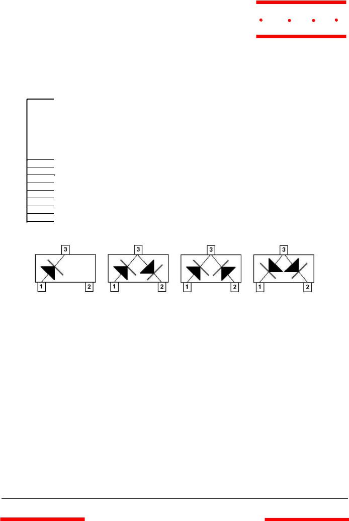
Bidirectional-low-forward available with “ -04” suffix (Figure 2)
Tape & Reel EIA Standard 481.
Mechanical Data
Epoxy meets UL 94 V-0 flammability rating
Moisture Sensitivity Level 1
Halogen free available upon request by adding suffix "-HF"
Mounting Position: Any
Weight: .008 grams (approx.)
MAXIMUM RATINGS
Operating Temperature: -55oC to +125oC
Storage Temperature: -55oC to +150oC
Power Dissipation: 200 mWatts @ Tamb=25oC
|
|
BAS40 IF |
=200mA@ Ta =25oC |
|
Forward Continuous Current: BAS70 IF |
=70mA @ Ta =25oC |
|
|
Surge Forward Current: |
BAS40 IFSM=600mA @ tp<1s, Tamb=25oC |
|
|
|
BAS70 IFSM=100mA @ tp<1s, Tamb=25oC |
|
DESCRIPTION
Various configurations of Schottky barrier’ s diodes in SOT-23 package are provided for general-purpose use in high-speed switching ,mixers and detector applications. They may also be used for signal integrity and counteract the transmission-line effects with (PC) board trances by clamping over/and undershoot from signal reflections with the schottky-low-threshold voltages.
This type of termination also does not depend on matching the transmission line characteristic impedance, making it particularly useful where line impendance is unknown or a variable. This methode of termination can control distortions of clock, data, address, and control lines as well as provides a stabilizing effect on signal jitter. It can also significantly reduce power consumption compared to standard resistor-based termination methods.
BAS40
THRU
BAS70
Surface Mount
Schottky Barrier Diode
200 mWatt
SOT-23
A
D
|
|
C |
B |
|
|
F |
E |
|
|
|
|
G |
|
H |
|
J |
|
|
K |
|
|
|
|
|
|
DIMENSIONS |
|
|
|
|
INCHES |
|
MM |
|
|
DIM |
MIN |
MAX |
MIN |
MAX |
NOTE |
A |
.110 |
.120 |
2.80 |
3.04 |
|
B |
.083 |
.104 |
2.10 |
2.64 |
|
C |
.047 |
.055 |
1.20 |
1.40 |
|
D |
.035 |
.041 |
.89 |
1.03 |
|
E |
.070 |
.081 |
1.78 |
2.05 |
|
F |
.018 |
.024 |
.45 |
.60 |
|
G |
.0005 |
.0039 |
.013 |
.100 |
|
H |
.035 |
.044 |
.89 |
1.12 |
|
J |
.003 |
.007 |
.085 |
.180 |
|
K |
.015 |
.020 |
.37 |
.51 |
|
Suggested Solder
Pad Layout
 .031
.031 
.800
.035
.900
.079 |
inches |
2.000 |
mm |
.037
.950
.037
.950
www.mccsemi.com
Revision: D |
1 of 4 |
2013/11/25 |
BAS40 and BAS70
M C C
TM
Micro Commercial Components
ELECTRICAL CHARACTERISTICS PER DIODE @ 250C Unless otherwise specified
|
|
|
|
Reverse |
Leakage Current |
|
|
|
|
|
|
|
|
|
|
|
Repetitive |
Pulse test |
|
|
|
|
Reverse |
Thermal |
Capacitance |
||
|
|
|
Breakdown |
Forward Voltage Pulse Test |
|||||||||
|
|
|
Peak Reverse |
tp < 300µs @ |
Recovery |
Resistance |
At VR = 0V |
||||||
|
|
|
Voltage |
|
|
tp < 300µs |
|||||||
|
|
|
Voltage |
|
|
|
|
Time from |
Junction to |
F = 1 MHz |
|||
|
|
|
Tested with |
|
|
|
at IF = 1 mA |
||||||
|
|
|
|
For BAS40 |
|
IF = 10 mA |
Ambient Air |
Ctot |
|||||
|
|
|
|
10µA Pulse |
|
at IF = 40 mA |
|||||||
DEVICE |
DEVICE |
|
|
VR = 30 V |
|
through |
|
|
|||||
FIGURE |
|
|
|
|
|
|
|
|
|||||
|
|
|
|
|
|
|
|
IR=10mA to |
|
|
|||
TYPE |
MARKING |
|
|
|
|
|
|
|
|
|
|
||
|
|
|
|
|
For BAS70 |
|
|
|
|
IR=1mA |
|
|
|
|
|
|
VRRM |
V(BR)R |
VR = 50 V |
|
|
VF (mV) |
trr (ns) |
|
|
||
|
|
|
(VOLTS) |
|
|
|
|
RthJA (K/W) |
pF |
||||
|
|
|
(VOLTS) |
IR (nA) |
|
|
|
|
|||||
|
|
|
|
|
|
|
|
|
|
|
|||
|
|
|
|
|
|
|
|
|
|
|
|
||
|
|
|
TYP |
MIN |
TYP |
MAX |
IF=1mA |
|
IF=15mA |
IF=40mA |
MAX |
MAX |
MAX |
|
|
|
|
|
|
|
|
|
|
|
|
|
|
BAS40 |
43 |
1 |
40 |
40 |
10 |
200 |
380 |
|
|
1000 |
5 |
430 |
5 |
|
|
|
|
|
|
|
|
|
|
|
|
|
|
BAS40-04 |
44 |
2 |
40 |
40 |
10 |
200 |
380 |
|
|
1000 |
5 |
430 |
5 |
|
|
|
|
|
|
|
|
|
|
|
|
|
|
BAS40-05 |
45 |
3 |
40 |
40 |
10 |
200 |
380 |
|
|
1000 |
5 |
430 |
5 |
|
|
|
|
|
|
|
|
|
|
|
|
|
|
BAS40-06 |
46 |
4 |
40 |
40 |
10 |
200 |
380 |
|
|
1000 |
5 |
430 |
5 |
|
|
|
|
|
|
|
|
|
|
|
|
|
|
BAS70 |
73 |
1 |
70 |
70 |
10 |
200 |
410 |
|
1000 |
|
5 |
430 |
2 |
|
|
|
|
|
|
|
|
|
|
|
|
|
|
BAS70-04 |
74 |
2 |
70 |
70 |
10 |
200 |
410 |
|
1000 |
|
5 |
430 |
2 |
|
|
|
|
|
|
|
|
|
|
|
|
|
|
BAS70-05 |
75 |
3 |
70 |
70 |
10 |
200 |
410 |
|
1000 |
|
5 |
430 |
2 |
|
|
|
|
|
|
|
|
|
|
|
|
|
|
BAS70-06 |
76 |
4 |
70 |
70 |
10 |
200 |
410 |
|
1000 |
|
5 |
430 |
2 |
|
|
|
|
|
|
|
|
|
|
|
|
|
|
Figure 1 |
Figure 2 |
Figure 3 |
Figure 4 |
|
|
|
|
www.mccsemi.com
Revision: D |
2 of 4 |
2013/11/25 |
 Loading...