


 Loading...
R E F E R E N C E

INTRODUCTION
Dear Customer,
Congratulations on your purchase of the world’s finest brand of car audio equipment. At MB Quart, we are pleased you chose our product. Through years of engineering expertise, hand craftsmanship and critical testing procedures, we have created a wide range of products that reproduce music with all the clarity and richness you deserve.
For maximum performance we recommend you have your new MB Quart product installed by an Authorized MB Quart Dealer. Please read your warranty and retain your receipt and original carton for possible future use.
Great product and competent installations are only a piece of the puzzle when it comes to your system. Make sure that your installer is using quality accessories in your installation. Poor quality RCA cables and speaker wire can effect the performance and sound quality of your system. When installing, or having your system installed, use the best. Insist on it! After all, your new system deserves nothing but the best.
To get a free brochure on MB Quart products and accessories, in the U.S. call 1-800-962-7757 or FAX 1-800-327-3777.
For all other countries, call +49 6261 638-0 or FAX +49 6261 638-129.
PRACTICE SAFE SOUND™
Continuous exposure to sound pressure levels over 100dB may cause permanent hearing loss. High powered auto sound systems may produce sound pressure levels well over 130dB. Use common sense and practice safe sound.
If, after reading your manual, you still have questions regarding this product, we recommend that you see your MB Quart dealer. If you need further assistance, you can call us direct at 1-800-962-4412. Be sure to have your serial number, model number and date of purchase available when you call.
The serial number can be found on the outside of the box. Please record it in the space provided below as your permanent record. This will serve as verification of your factory warranty and may become useful in recovering your amplifier if it is ever stolen.
Serial Number:___________________________________________
Model Number: __________________________________________
TABLE OF CONTENTS
Introduction |
2 |
|
Operation |
9-10 |
|
||||
Safety Instructions . . . . . . . . . . . . . . . . . . . . . |
. 3 |
|
Set-up Features . . . . . . . . . . . . . . . . . . . . . |
. . . . 9 |
Design Features . . . . . . . . . . . . . . . . . . . . . . |
4-5 |
|
Front End Defeat . . . . . . . . . . . . . . . . . . . . . |
. . . 9 |
Installation . . . . . . . . . . . . . . . . . . . . . . . . . . |
5-9 |
|
Crossover . . . . . . . . . . . . . . . . . . . . . . . . . . . |
. . 10 |
Installation Considerations . . . . . . . . . . . . . . . |
. 5 |
|
Gain. . . . . . . . . . . . . . . . . . . . . . . . . . . . . . . . |
. . 10 |
Mounting Locations. . . . . . . . . . . . . . . . . . . . . |
. 6 |
|
Troubleshooting . . . . . . . . . . . . . . . . . . . . |
11-12 |
Battery and Charging . . . . . . . . . . . . . . . . . . . |
. 6 |
|
Specifications . . . . . . . . . . . . . . . . . . . . . . . |
. . 12 |
Wiring the System . . . . . . . . . . . . . . . . . . . . . . |
. 7 |
|
Limited Warranty Information . . . . . . . . . . . |
. 13 |
|
|
|
|
|
NOTE: Review each section for more detailed information.
2

GETTING STARTED
Welcome to MB Quart! This manual is designed to provide information for the owner, salesperson and installer. For those of you who want quick information on how to install this product, please turn to the Installation Section of this manual. Other information can be located by using the Table of Contents. We, at MB Quart, have worked very hard to make sure all the information in this manual is current. But, as we are constantly finding new ways to improve our product, this information is subject to change without notice.
SAFETY INSTRUCTIONS
This symbol with “WARNING” is intended to alert the user to the presence of important instructions. Failure to heed the instructions will result in severe injury or death.
This symbol with “CAUTION” is intended to alert the user to the presence of important instructions. Failure to heed the instructions can result in injury or unit damage.
CAUTION: To prevent injury and damage to the unit, please read and follow the instructions in this manual. We want you to enjoy this system, not get a headache.
CAUTION If you feel unsure about installing this system yourself, have it installed by an authorized MB Quart dealer.
CAUTION Before installation, disconnect the battery negative (-) terminal to prevent damage to the unit, fire and/or possible injury.
|
|
|
CONTENTS OF CARTON |
Model RAA2400 2-Channel Amplifier |
|
(2) |
Speaker Plug Connectors |
|
|||
Installation & Operation Manual |
|
(1) |
Power Plug Connector |
Mounting Hardware Kit |
|
(1) |
8/32" Allen Wrench |
The hardware kit included with each amplifier contains the mounting hardware necessary to secure the amplifier to the vehicle.
Visit our web site for the latest information on all MB Quart products.
www.mbquart.com
3
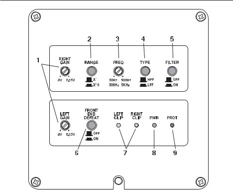
DESIGN FEATURES
Controls
1.Gain Adjuster – These can be adjusted to match output levels from a variety of source units individually for the left and right inputs.
2.Crossover Multiplier Range Switch – Used to set the multiplier for the left and right crossover frequencies between x1 and x10. A setting of x1 leaves the adjustable crossover frequency from 50-500Hz. A setting of x10 changes the adjustable crossover frequency to 500-5KHz (5000Hz)
3.Crossover Frequency Adjuster– Used to adjust the left and right crossover frequency. Variable from 50Hz to 500Hz in x1 mode, and 500-5KHz in x10 mode.
4.Crossover Type – Is used for selecting High-Pass Filter (HPF) or Low-Pass Filter (LPF) operation for the left and right speaker outputs.
5.Crossover Filter Switch – Off sets the crossover to all-pass, adjustments to the crossover range, freq, and type are bypassed. On allows adjustments to the crossover settings to be used.
6.Front End Defeat – Used to reroute the input signal around the signal processing circuitry within the amplifier. While in the ON position, all gain and crossover functions are bypassed.
7.Clipping LED Indicators – These Yellow LEDs illuminate if clipping is detected for either the left or right speaker outputs.
8.Power LED – This Green LED illuminates when the unit is turned on.
9.Protect LED – This Red LED illuminates if a short circuit or too low of an impedance is detected at the speaker connections or if the amplifier reaches thermal protection. The amplifier will automatically shut down if this occurs.
4
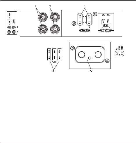
DESIGN FEATURES
Connections
Left Side
Right Side
1.RCA Line Output Jacks – These outputs provide a convenient source for daisy-chaining an additional amplifier without running an extra set of RCA cables from the front of the vehicle. These are pass-thru only and are not effected by crossover or gain adjustments.
2.RCA Input Jacks – The industry standard RCA jacks provide an easy connection for line level input. They are plated to resist the signal degradation caused by corrosion.
3.Speaker Plug Receptacle – Receptacle for the speaker plug connector. These connectors (+ and –) will accept wire sizes from 12 AWG to 18 AWG.
4.Fuses – These ATC fuses are easily accessible in case of failure. Always replace fuses with same type and rating. See Specifications for fuse ratings.
5.Power Plug Receptacle – Receptacle for the power plug connector. The power (+12V DC) and ground wire connectors will accommodate up to a 2 AWG wire. The Remote wire connector will accommodate sizes from 12 AWG to 18 AWG. The Remote terminal is used to remotely turn-on and turn-off the amplifier when +12V DC is applied.
INSTALLATION
INSTALLATION CONSIDERATIONS
The following is a list of tools needed for installation:
Volt/Ohm Meter
Wire strippers
Wire crimpers
Wire cutters
#2 Phillips screwdriver
Battery post wrench
Hand held drill w/assorted bits
1/8" diameter heatshrink tubing
Assorted connectors
Adequate Length—Red Power Wire
Adequate Length—Remote Turn-on Wire
Adequate Length—Black Grounding Wire
This section focuses on some of the vehicle considerations for installing your new amplifier. Pre-planning your system layout and best wiring routes will save installation time. When deciding on the
layout of your new system, be sure that each component will be easily accessible for making adjustments.
5
Loading...