

Mazda 6 Facelift 2005 Training Manual
TRAINING MANUAL
Mazda6 Facelift

No part of this hardcopy may be reproduced in any form without prior permission of
Mazda Motor Europe GmbH.
The illustrations, technical information, data and descriptive text in this issue, to the best
of our knowledge, were correct at the time of going to print.
No liability can be accepted for any inaccuracies or omissions in this publication,
although every possible care has been taken to make it as complete and accurate as
possible.
© 2005
Mazda Motor Europe GmbH
Training Services
Contents
SectionTitle
General Information
Engine
Suspension
Brakes
Transmission / Transaxle
Restraints
00
01
02
04
05
08
Body & Accessories
Service Training Mazda6 Facelift
09

Service Training Mazda6 Facelift

00
General Information

00 General Information
Vehicle Identification Number (VIN) Code.........................................................1
Applicable VIN ................................................................................................1
Engine / Transaxle Combinations......................................................................2
Scheduled Maintenance .....................................................................................3
Europe ............................................................................................................3
Table of Contents 00 Service Training Mazda6 Facelift

General Information
Vehicle Identification Number (VIN) Code
JMZ GG 1 2 3 2 0 1 1 2 3 4 5 6
Serial No.
0= Hiroshima
1= Hofu
Plant
Dummy 0, 6 to 9, A to Z
2= 5MTX
6= 6MTX
Transmission
Engine Type
Body style
Remarks
7= 5ATX
3= 2.3L (L3)
8= 1.8L (L8)
F= 2.0L (LF)
R= MZR-CD (RF Turbo)-Hi
T= MZR-CD (RF Turbo)-Standard
2= 4SD
4= 5HB
9= WAGON
8= 4WD
1= 2WD
Applicable VIN
JMZ GG1236*# 600001—
JMZ GG12360# 600001—
JMZ GG1282*# 600001—
JMZ GG12820# 600001—
JMZ GG12F6*# 600001—
JMZ GG12F60# 600001—
JMZ GG12R6*# 600001—
JMZ GG12R60# 600001—
JMZ GG12T6*# 600001—
JMZ GG12T60# 600001—
JMZ GG1436*# 600001—
Vehicle type
World manufacturer indication
JMZ GG14360# 600001—
JMZ GG1482*# 600001—
JMZ GG14820# 600001—
JMZ GG14F6*# 600001—
JMZ GG14F60# 600001—
JMZ GG14R6*# 600001—
JMZ GG14R60# 600001—
JMZ GG14T6*# 600001—
JMZ GG14T60# 600001—
JMZ GY1936*# 400001—
JMZ GY1982*# 400001—
GG= Mazda6 (4SD, 5HB)
GY= Mazda6 (WAGON)
JMZ= European (L.H.D. U.K.)
M6FL_00T001
JMZ GY19820# 400001—
JMZ GY19F6*# 400001—
JMZ GY19F60# 400001—
JMZ GY19R6*# 400001—
JMZ GY19R60# 400001—
JMZ GY19T6*# 400001—
JMZ GY19T60# 400001—
JMZ GY8937*# 400001—
JMZ GY89370# 400001—
Service Training Mazda6 Facelift 00-1

General Information
Engine / Transaxle Combinations
• All engines have been revised. New transaxles have been added to the range. The
following engine/transaxle combinations are available:
L8
1.8L
88 KW (120 HP)
at 5,500 rpm
165 Nm
at 4,300 rpm
LF
2.0L
108 KW (147 HP)
at 6,500 rpm
184 Nm
at 4,000 rpm
L3
2.3L
122 KW (166 HP)
at 6,500 rpm
G35M-R
5-speed
manual
transaxle
X
G66M-R
6-speed
manual
transaxle
X
X
A26M-R
6-speed
manual
transaxle
FS5A-EL
5-speed
automatic
transaxle
(front wheel drive)
X
JA5AX-EL
5-speed
automatic
transaxle
(All Wheel
D
AWD
rive (
XX
))
207 Nm
at 4,000 rpm
RF Turbo STD
89 KW (121 HP)
at 3,500 rpm
320 Nm
at 2,000 rpm
RF Turbo HI
105 KW (143 HP)
at 3,500 rpm
360 Nm
at 2,000 rpm
2.0L
2.0L
X
X
M6FL_00T002
00-2 Service Training Mazda6 Facelift
General Information
Scheduled Maintenance
Europe
Maintenance interval (number of momths or km (miles) which ever comes first)
Maintenance items
PETROL ENGINE
Engine valve clearance
Spark plugs
Air cleaner element
Evaporation system(if installed)
DIESEL ENGINE
Engine valve clearance
Engine timing belt *2
Fuel filter
Fuel injection system
Fuel system (Drain water)
Air cleaner element*1
PETROL AND DIESEL ENGINE
Engine oil*3
Engine oil filter *3
Drive belt *4
Cooling system (including coolant level
adjustment)
Engine coolant
Fuel lines and hoses
Battery electrolyte level and specific gravity
Brakes lines hoses and connections
Brake fluid *6
Parking brake
Disc brakes
Steering operation and linkages
Manual transaxle oil
Automatic transaxle fluid level
Rear differential oil (for 4 WD)
Transfer oil (for 4 WD)
Front and rear suspension and ball joints
Drive shaft dus boots
Exhaust system and heat shields
Body condtion
(for rust, corrosion and perforation)
Cabin air filter (if installed)
Tires (including spare tire)
(with inflation pressure adjustment)
Months
X1000 km
X1000 miles
FL 22 type *5
Others
12 24 36 48 60 72 84 96 108
20 40 60 80 100 120 140 160 180
12,5 25 37,5 50 62,5 75 87,5 100 112,5
Audible inspect every 120,000km (75,000 miles), if noisy adjust
Replace every 100,000km (62,500miles)
RRR
III
II
Replace every 120,000 km (75,000 miles)
RRR
IIII
DDDDDDDDD
CCRCCRCCR
RRRRRRRRR
RRRRRRRRR
III
IIII
Replace every 200,000 km (125,000 miles) 0r 11 years
Replace at first 100,000 km (62,500 miles) or 4 years;
after that, every 2years
IIII
IIIIIIIII
IIIIIIIII
RRRR
IIIIIIIII
IIIIIIIII
IIIIIIIII
R
III
*7 *8
*8
IIII
IIII
Inspect every 80,000 km (50,000 miles) or 5 years
Inspect annualy
RRRR
IIIIIIII
I
M6FL_00T003
I: Inspect: Inspect and clean, repair, adjust, or replace if necessary.
R: Replace
C: Clean
D: Drain
Service Training Mazda6 Facelift 00-3

General Information
Remarks:
*1 If the vehicle is operated in very dusty or sandy areas, clean and if necessary, replace the
air filter more often than the recommended intervals.
*2 Replacement of the timing belt is required at every 120,000 km (75,000 miles). Failure to
replace the timing belt may result in damage to the engine.
*3 If the vehicle is operated under any of the following conditions, change the engine oil and
oil filter every 10,000 km (6,250 miles) or shorter.
a) Driving in dusty conditions
b) Extended periods of idling or low speed operation
c) Driving for long period in cold temperatures or driving regularly at short distance only
*4 Also inspect and adjust the power steering and air conditioner drive belts, if installed.
*5 Use FL22 type coolant in vehicles with the inscription “FL22” on the radiator cap itself or
the surrounding area. Use FL22 when replacing the coolant.
*6 If the brakes are used extensively (for example, continuous hard driving or mountain
driving) or if the vehicle is operated in extremely humid climates, change the brake fluid
annually.
*7 If the vehicle is operated under any of the following conditions, change the rear differential
oil every 45,000 km (28,100 miles).
a) Towing a trailer or using a car-top carrier
b) Driving in dusty, sandy or wet condition
c) Extended periods of idling or low speed operation
d) Repeated short trips of less than 16 km (10 miles)
*8 If this component has been submerged in water, the oil should be changed.
00-4 Service Training Mazda6 Facelift

01
Engines

01 Engine
Table of Contents
Petrol Engines
Mechanics............................................................................................................1
Cylinder Head Cover.......................................................................................1
Valve Mechanism............................................................................................2
Lubrication ......................................................................................................3
Intake-Air System................................................................................................4
Electronic Throttle Control...............................................................................5
Exhaust System...................................................................................................6
Charging System.................................................................................................7
Generator Design............................................................................................7
Generator Electrical Diagram ...................................................................8
Ignition System....................................................................................................9
Engine Control System.....................................................................................10
Structural View..............................................................................................10
Powertrain Control Module (PCM)................................................................11
PCM Connector (Harness Side Shown) .................................................11
Overview.......................................................................................................12
Wiring Diagram.............................................................................................14
Accelerator Pedal Position (APP) Sensor.....................................................18
Throttle Valve Actuator .................................................................................20
Throttle Position (TP) Sensor........................................................................21
TP Sensor Voltage Characteristics......................................................... 22
Heated Oxygen Sensors (HO2S)..................................................................23
Front HO2S ............................................................................................24
Rear HO2S.............................................................................................25
Crankshaft Position (CKP) Sensor................................................................26
Camshaft Position (CMP) Sensor.................................................................28
Diesel Engines
Mechanics..........................................................................................................29
Pistons..........................................................................................................30
Cylinder Head...............................................................................................31
Lubrication.........................................................................................................32
Specification..................................................................................................32
Engine Oil...............................................................................................32
Parts Location...............................................................................................33
Engine Oil .....................................................................................................34
Table of Contents 01 Service Training Mazda6 Facelift

01 Engine
Table of Contents (continued)
Oil Dipstick....................................................................................................35
Oil Dilution Calculation..................................................................................36
Oil Cooler and Oil Filter.................................................................................37
Cooling System.................................................................................................39
Specifications................................................................................................39
Parts Location...............................................................................................40
Intake-air System...............................................................................................41
Parts Location...............................................................................................41
Turbocharger ................................................................................................42
Manifold Absolute Pressure Sensor..............................................................43
Fuel System.......................................................................................................44
Parts Location...............................................................................................44
Common Rail................................................................................................45
Injectors ........................................................................................................46
Injector Correction Factors ..................................................................... 48
Injection Amount Learning Function .......................................................49
Emission System...............................................................................................50
Parts Location...............................................................................................50
Exhaust System.................................................................................................51
Parts Location...............................................................................................51
Exhaust Gas Recirculation System.................................................................52
EGR Valve....................................................................................................52
EGR Cooler...................................................................................................55
Intake Shutter Valve......................................................................................56
Diesel Particulate Filter System.......................................................................59
Diesel Particulates ........................................................................................59
Diesel Particulate Filter.................................................................................60
DPF Differential Pressure Sensor.................................................................63
Diagnostics.............................................................................................66
Exhaust Gas Temperature Sensors..............................................................68
Heated Oxygen Sensor.................................................................................70
DPF Indicator Light.......................................................................................72
Regeneration Control....................................................................................73
Soot Amount Calculation........................................................................73
Regeneration Process............................................................................ 75
Regeneration Intervals............................................................................76
Service Training Mazda6 Facelift Table of Contents 01

01 Engine
Table of Contents (continued)
Charging System...............................................................................................77
Specifications................................................................................................77
Parts Location...............................................................................................77
Smart Charging System................................................................................ 78
Control System..................................................................................................79
Parts Location...............................................................................................79
Wiring Diagram.............................................................................................82
Powertrain Control Module............................................................................86
Crankshaft Position Sensor...........................................................................87
Camshaft Position Sensor.............................................................................88
Accelerator Pedal Position Sensor................................................................89
Power Steering Pressure Switch...................................................................92
Service And Repair.......................................................................................93
Replacing the Engine Oil........................................................................93
Manual Regeneration .............................................................................93
Replacing the MAF Sensor.....................................................................94
Replacing the High-Pressure Pump........................................................94
Replacing Injectors.................................................................................94
Replacing the EGR Valve Or The ISV....................................................95
Replacing the DPF..................................................................................95
Replacing the DPF Differential Pressure Sensor....................................95
Replacing the HO2S...............................................................................96
Replacing the PCM.................................................................................96
On-board Diagnostic System...........................................................................97
Self Test........................................................................................................97
PID Monitor...................................................................................................98
Simulation Test...........................................................................................101
Table of Contents 01 Service Training Mazda6 Facelift
Engine Petrol Engines
Mechanics
M6FL_01057
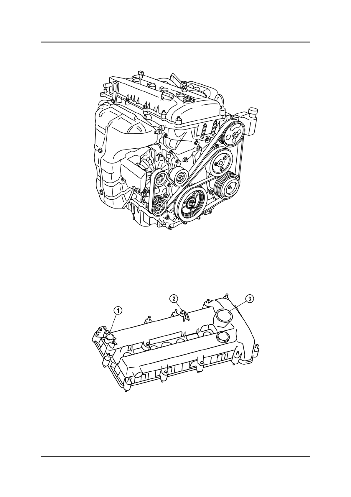
Cylinder Head Cover
• The cylinder head cover is made of plastic. On LF and L3 engines a hole is provided for
installation of the OCV (Oil Control Valve).
• A dipstick insertion hole has been equipped to the cylinder head cover.
1 CMP (Camshaft Position) sensor
attachment part
2 Dipstick insertion hole
3 OCV attachment hole (LF, L3)
M6FL_01001
Service Training Mazda6 Facelift 01-1
Petrol Engines Engine
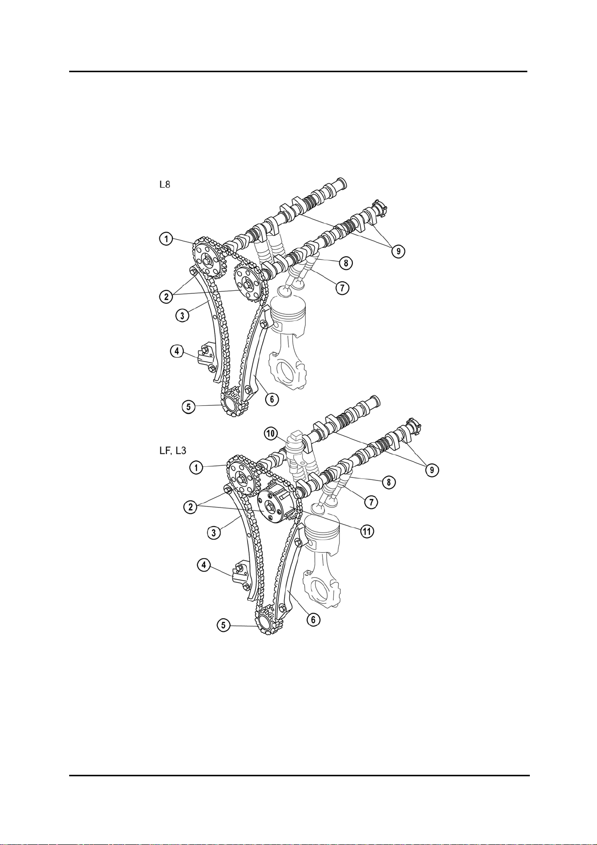
Valve Mechanism
• For the LF engine the variable valve timing system has been carried over from the L3
engine.
• All engines use a sensor ring with 6 reference cams for the CMP Sensor on the intake
camshaft.
M6FL_01002
1 Timing chain 7 Valve assembly
2 Camshaft sprocket 8 Tappet
3 Tensioner arm 9 Camshafts
4 Chain tensioner 10 OCV
5 Crankshaft sprocket 11 Variable valve timing actuator
6 Chain guide
01-2 Service Training Mazda6 Facelift
Engine Petrol Engines
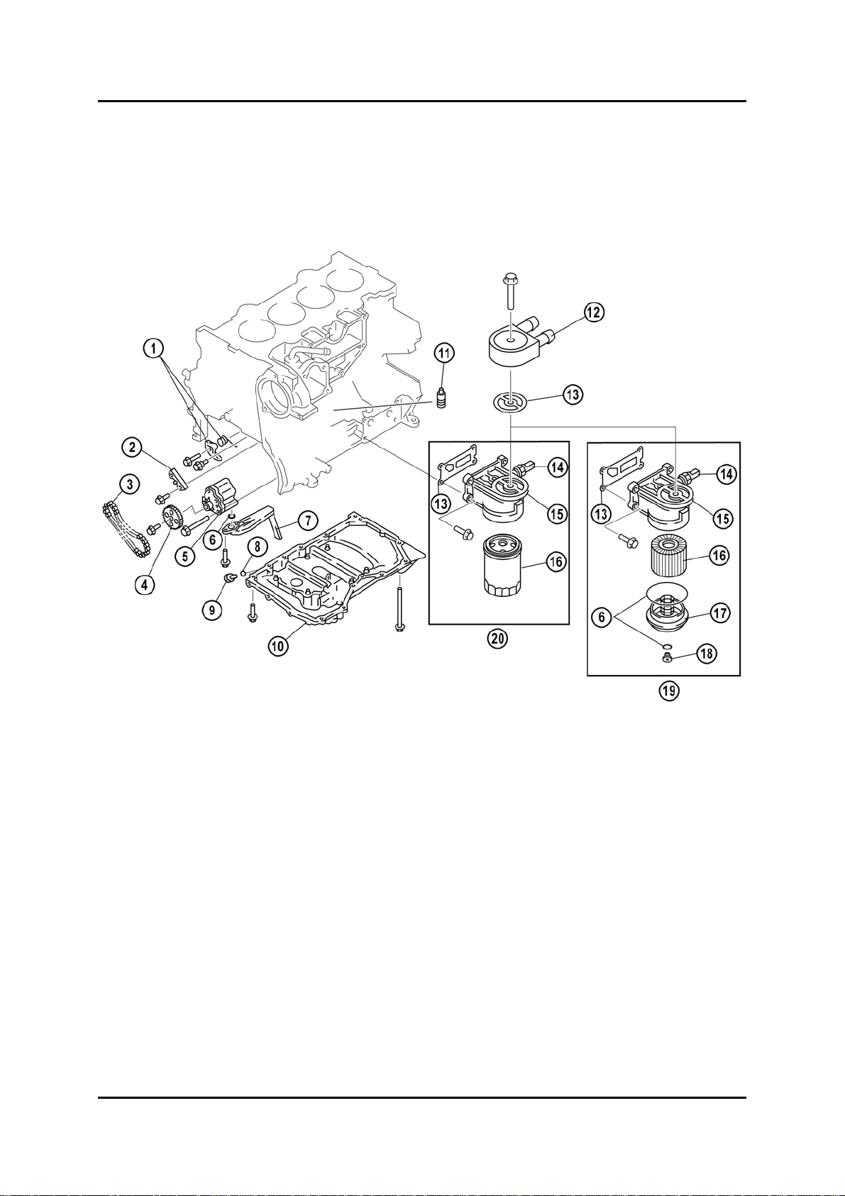
Lubrication
• The lubrication system has been carried over from the previous engines. Depending on
specification, both spin-on and cartridge type oil filters are available.
• The oil cooler is now installed on both the L3 and the LF engine.
1 Oil pump chain tensioner 11 Oil jet valve
2 Oil pump chain guide 12 Oil cooler (LF, L3)
3 Oil pump chain 13 Gasket
4 Oil pump sprocket 14 Oil pressure switch
5 Oil pump 15 Oil filter adapter
6 O-ring 16 Oil filter
7 Oil strainer 17 Oil filter cover
8 Washer 18 Oil filter drain plug
9 Oil pan drain plug 19 Cartridge type oil filter
10 Oil pan 20 Spin-on type oil filter
M6FL_01003
Service Training Mazda6 Facelift 01-3
Petrol Engines Engine
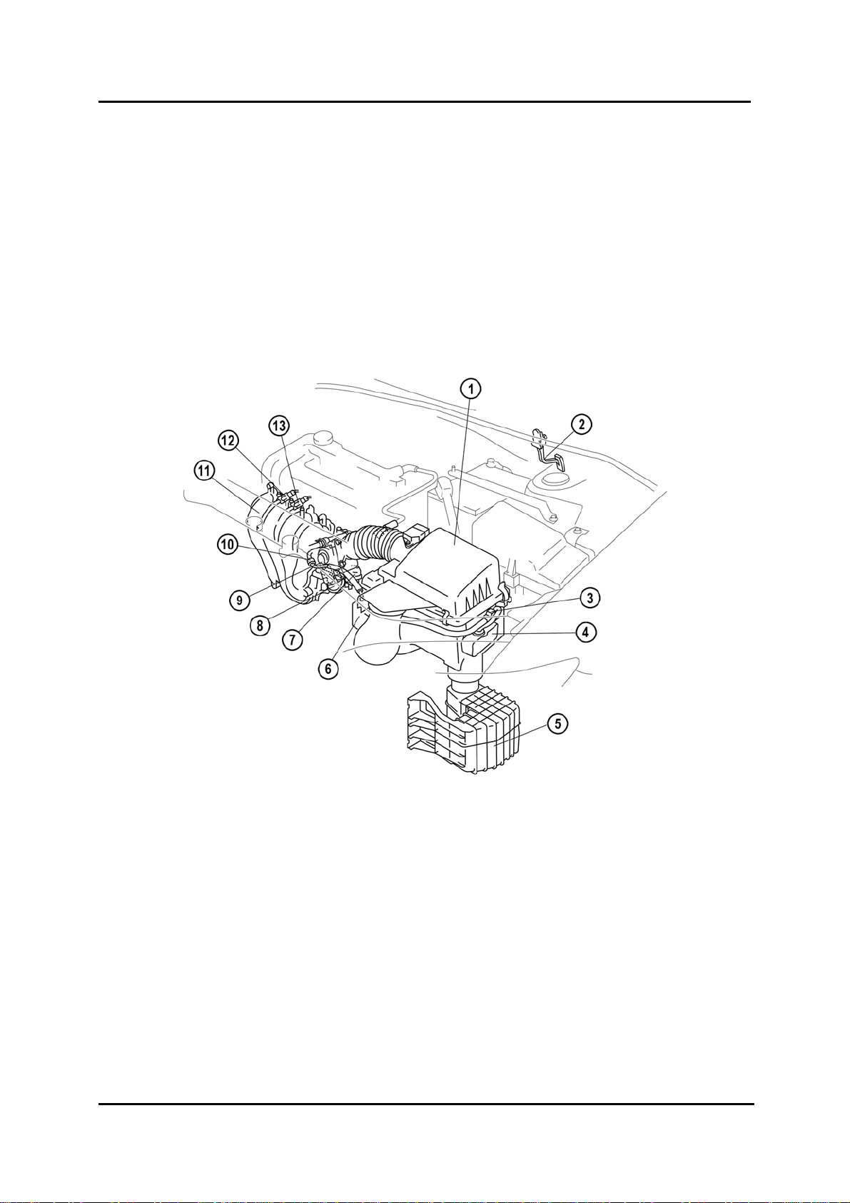
Intake-Air System
• The intake-air system has been basically carried over from the previous engines. It
comprises:
– VTCS (Variable Tumble Control System) (L8, LF, L3)
– VIS (Variable Intake-air System) (LF, L3)
– VAD (Variable Air Duct) (L3)
• All petrol engines now use an electronic throttle control.
• For the LF engine the VIS has been carried over from the L3 engine.
M6FL_01004
1 Air cleaner 8 VIS shutter valve actuator (LF, L3)
2 Accelerator pedal 9 Throttle body
3 VAD solenoid valve (L3) 10 VAD check valve (one-way) (L3)
4 VAD shutter valve (L3) 11 Intake manifold
5 Resonance chamber 12 VIS solenoid valve (LF, L3)
6 VAD vacuum chamber (L3) 13 VTCS solenoid valve
7 VTCS shutter valve actuator
01-4 Service Training Mazda6 Facelift
Engine Petrol Engines
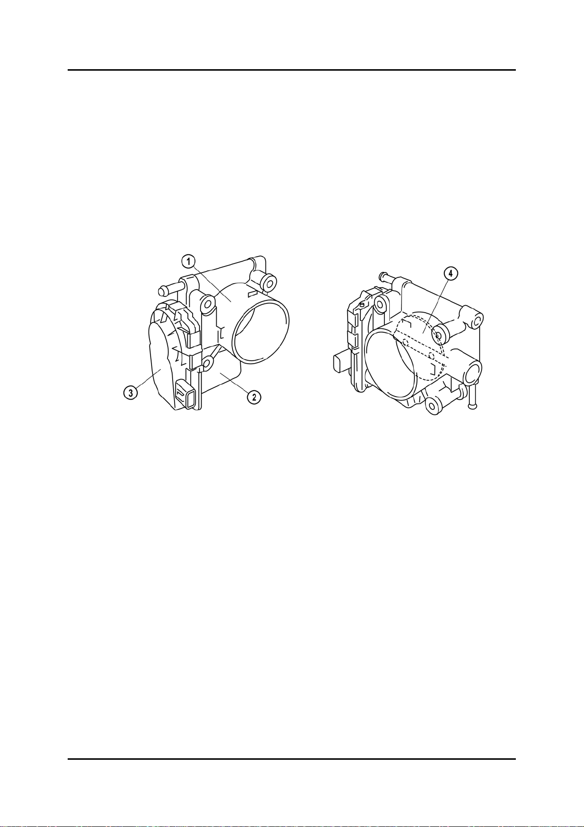
Electronic Throttle Control
• All engines are using an electronically controlled throttle body, which is quite similar to
the one on RX-8. This supersedes the IAC (Idle Air Control) valve.
• To keep moisture from freezing inside the throttle body, and thus to prevent the throttle
valve from getting stuck, engine coolant is circulated through the throttle body.
• The throttle body cannot be disassembled.
• When the throttle actuator is not energized, the throttle valve is maintained slightly open
by the force of the return spring. This allows limited operation of the engine in case of a
malfunction.
1 Throttle body 3 TP (Throttle Position) sensor
2 Throttle actuator 4 Throttle valve
M6FL_01005
Service Training Mazda6 Facelift 01-5

Petrol Engines Engine
Exhaust System
• The exhaust system has been carried over from the previous Mazda6.
• Vehicles specified with LF engine are now using the exhaust system with two main
silencers (previously used on L3 engines only).
M6FL_01006
1 Main silencer 5 HO2S (front)
2 Middle pipe 6 Exhaust manifold
3 HO2S (Heated Oxygen Sensor) (rear) 7 LF, L3
4 TWC (Three-Way Catalyst)
01-6 Service Training Mazda6 Facelift
Engine Petrol Engines
Charging System
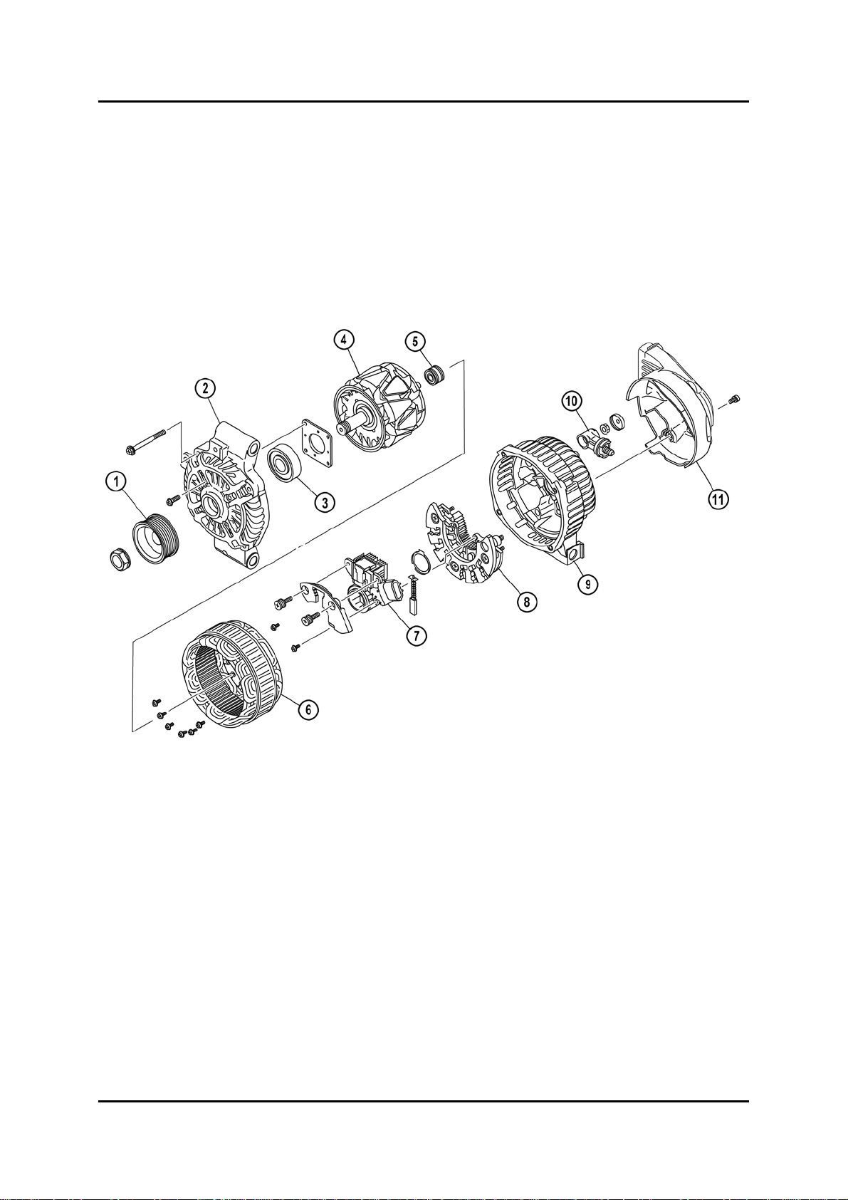
Generator Design
• Generator control is carried out by the PCM (Powertrain Control Module). Excitation
current in the field coil is increased or decreased by the power transistor built into the
generator. The power transistor is controlled by a duty signal from the PCM.
• A generator duct made of plastic, and a generator heat insulator made of iron have been
adopted to protect the generator from the exhaust manifold heat.
M6FL_01007
1 Pulley 7 Regulator component (built-in power
transistor)
2 Front cover 8 Rectifier
3 Front bearing 9 Rear cover
4 Rotor 10 Terminal B connector
5 Rear bearing 11 Heat insulator
6 Stator coil
Service Training Mazda6 Facelift 01-7
Petrol Engines Engine
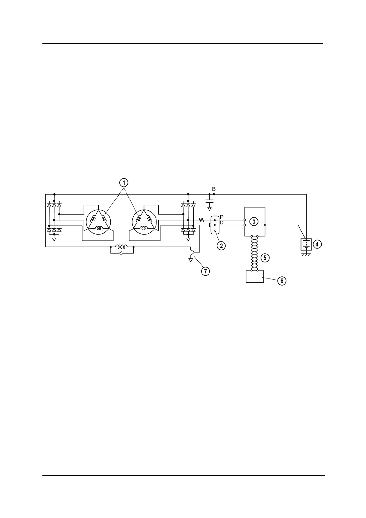
Generator Electrical Diagram
• Two delta connection type stator coils have been introduced. Due to this, the generator
operation noise (electrical noise) is reduced and pulsation occurring through voltage
rectifying in the stator coil is minimized, as a result, stable voltage output is supplied.
• The generator warning light in the instrument cluster illuminates under the following
conditions:
– Charging system voltage low input
– Charging system voltage high input
– IAT sensor circuit low input
– IAT sensor circuit high input
1 Stator coil 5 CAN (Controller Area Network)
2 Terminal not used 6 Instrument cluster (warning light)
3 PCM 7 Power transistor
4 Battery
M6FL_01008
01-8 Service Training Mazda6 Facelift
Engine Petrol Engines
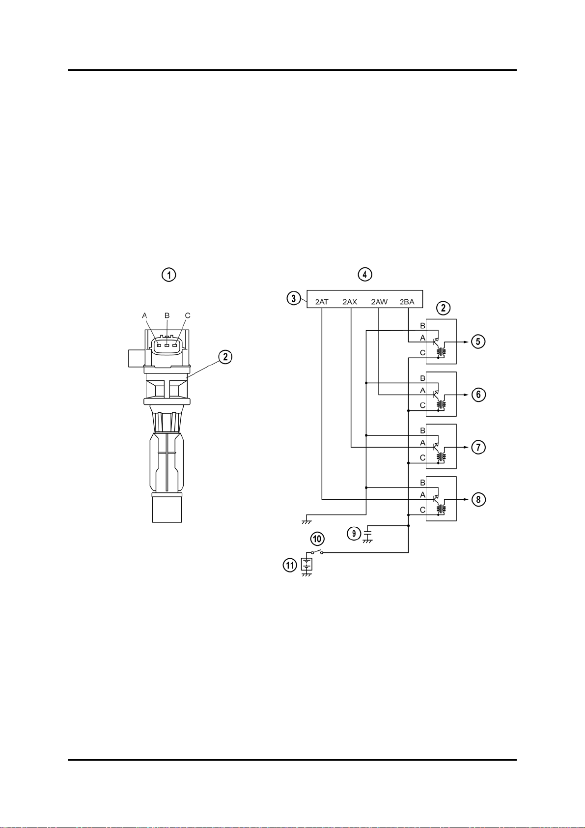
Ignition System
• The petrol engines use direct ignition coils which are installed directly to each spark plug.
By adopting direct ignition coils, high-tension leads have been eliminated in order to
simplify the parts of the ignition system, preventing voltage reduction, and improving the
firing efficiency.
• In addition to that, the use of direct ignition coils allows independent firing control.
• The direct ignition coil consists of an ignition coil, ignition coil connector, and boot area,
which has the same function as the current high-tension lead.
• The igniter has been integrated into each ignition coil.
• The firing timing of the coil is controlled by the PCM for optimum ignition timing control.
M6FL_01009
1 Ignition coil external view 7 Cylinder number No. 3
2 Ignition coil 8 Cylinder number No. 4
3 PCM 9 Condenser
4 Ignition coil electrical system wiring diagram 10 Ignition switch
5 Cylinder number No. 1 11 Battery
6 Cylinder number No. 2
Service Training Mazda6 Facelift 01-9
Petrol Engines Engine
Engine Control System
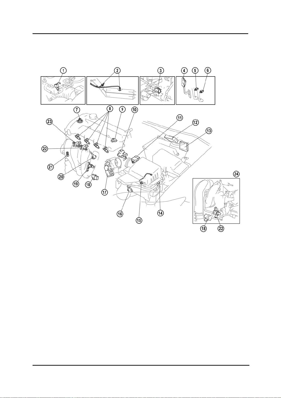
Structural View
M6FL_01010
1 Purge valve 13 PCM (LHD)
2 HO2S (front, rear) 14 VAD solenoid valve (L3)
3 ECT (Engine Coolant Temperature)
sensor
4 APP (Accelerator Pedal Position) sensor 16 TR (Transmission Range) switch (ATX (
5 Brake switch 17 TP sensor, throttle actuator
6 Clutch switch (MTX) 18 MAP (Manifold Absolute Pressure)
7 OCV (LF,L3) 19 CKP (Crankshaft Position) sensor
8 Fuel injectors 20 KS (Knock Sensor)
9 CMP sensor 21 P/S (Power Steering) pressure switch
10 EGR (Exhaust Gas Recirculation) valve 22 VTCS solenoid valve
11 MAF (Mass Air Flow) /
IAT (Intake Air Temperature) sensor
12 PCM (RHD) 24 L8 engine
15 Neutral switch (MTX (Manual
Transaxle))
Automatic Transaxle))
sensor
23 VIS solenoid valve (LF, L3)
01-10 Service Training Mazda6 Facelift
Engine Petrol Engines
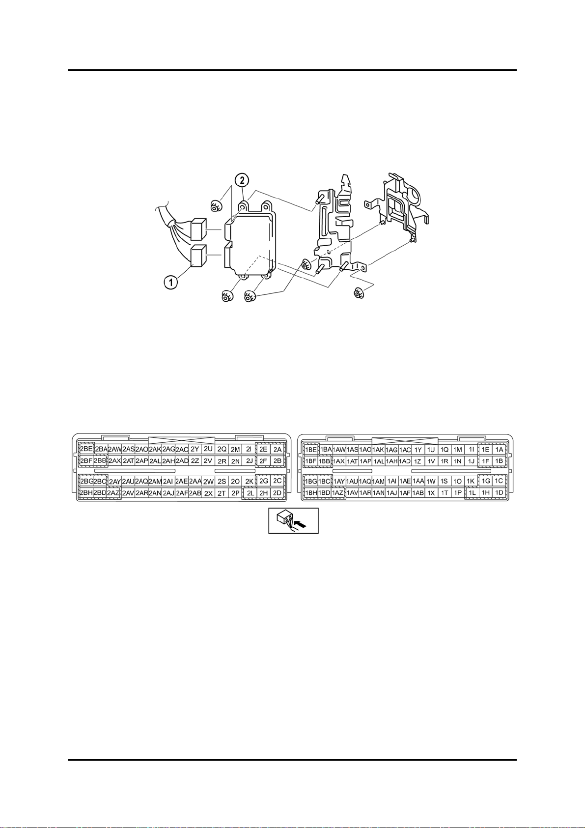
Powertrain Control Module (PCM)
• A PCM with integral BARO (Barometric Pressure) sensor has been introduced. It is
installed on the left-hand side under the dashboard.
• Right-hand-drive vehicles have two additional PCM covers secured with set bolts.
M6FL_01011
1 PCM connectors 2 PCM
PCM Connector (Harness Side Shown)
• The PCM has two connectors with 60 pins each.
M6FL_01012
Service Training Mazda6 Facelift 01-11
Petrol Engines Engine
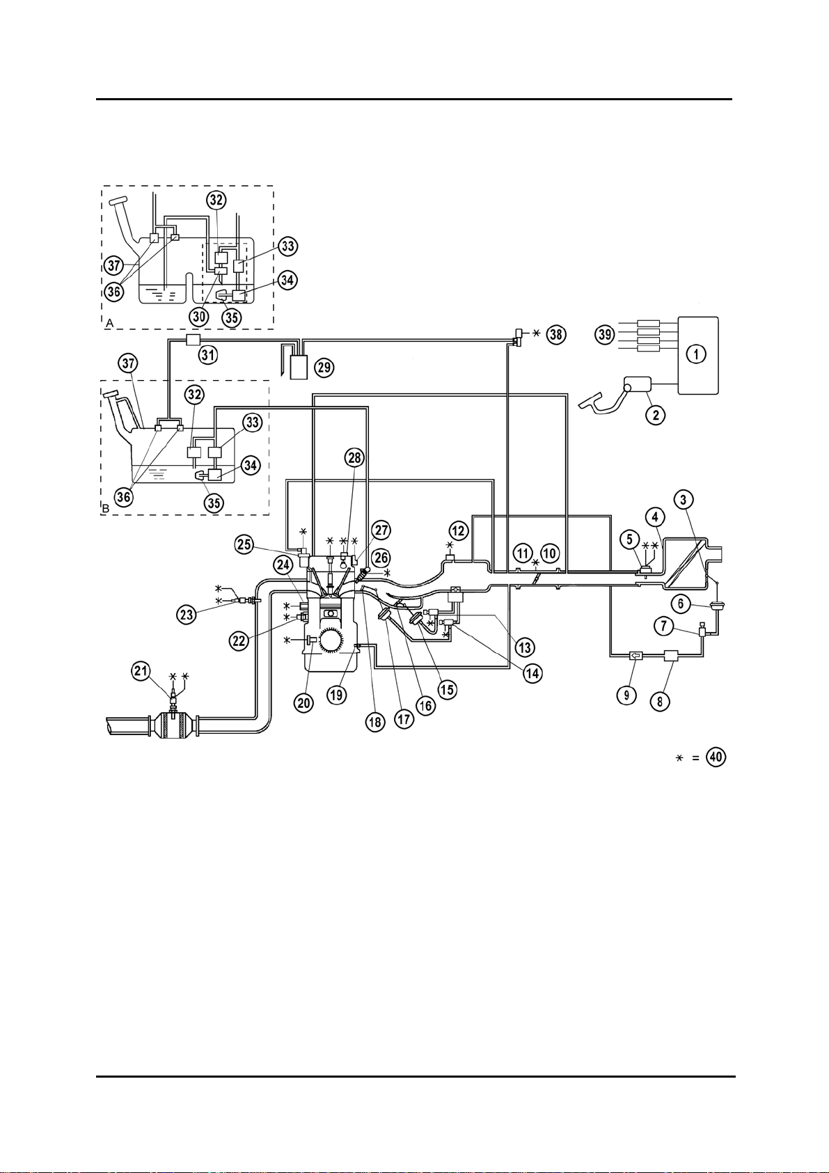
Overview
M6FL_01013
01-12 Service Training Mazda6 Facelift

Engine Petrol Engines
1 PCM 22 ECT sensor
2 APP sensor 23 HO2S (front)
3 VAD shutter valve (L3) 24 Knock sensor
4 Air cleaner 25 EGR valve
5 MAF sensor 26 Fuel injector
6 VAD shutter valve actuator (L3) 27 OCV (LF, L3)
7 VAD solenoid valve (L3) 28 CMP sensor
8 Vacuum chamber 29 Charcoal canister
9 VAD check valve (one-way) (L3) 30 Fuel pump (transfer)
10
11
12
13
14
15
16
17
18
19
20
21
TP sensor 31 Check valve (two-way)
Throttle actuator 32 Pressure regulator
MAP (Manifold Absolute Pressure) sensor 33 Fuel filter (high pressure)
VIS control solenoid valve (LF, L3) 34 Fuel pump
VTCS solenoid valve 35 Fuel filter (low pressure)
VIS shutter valve actuator (LF, L3) 36 Rollover valve
VIS shutter valve (LF, L3) 37 Fuel tank
VTCS shutter valve actuator 38 Purge solenoid valve
VTCS shutter valve 39 Ignition coils
PCV (Positive Crankcase Ventilation) valve 40 To PCM
CKP sensor A 4WD (4-Wheel Drive)
HO2S (rear) B 2WD (2-Wheel Drive)
Service Training Mazda6 Facelift 01-13
Petrol Engines Engine
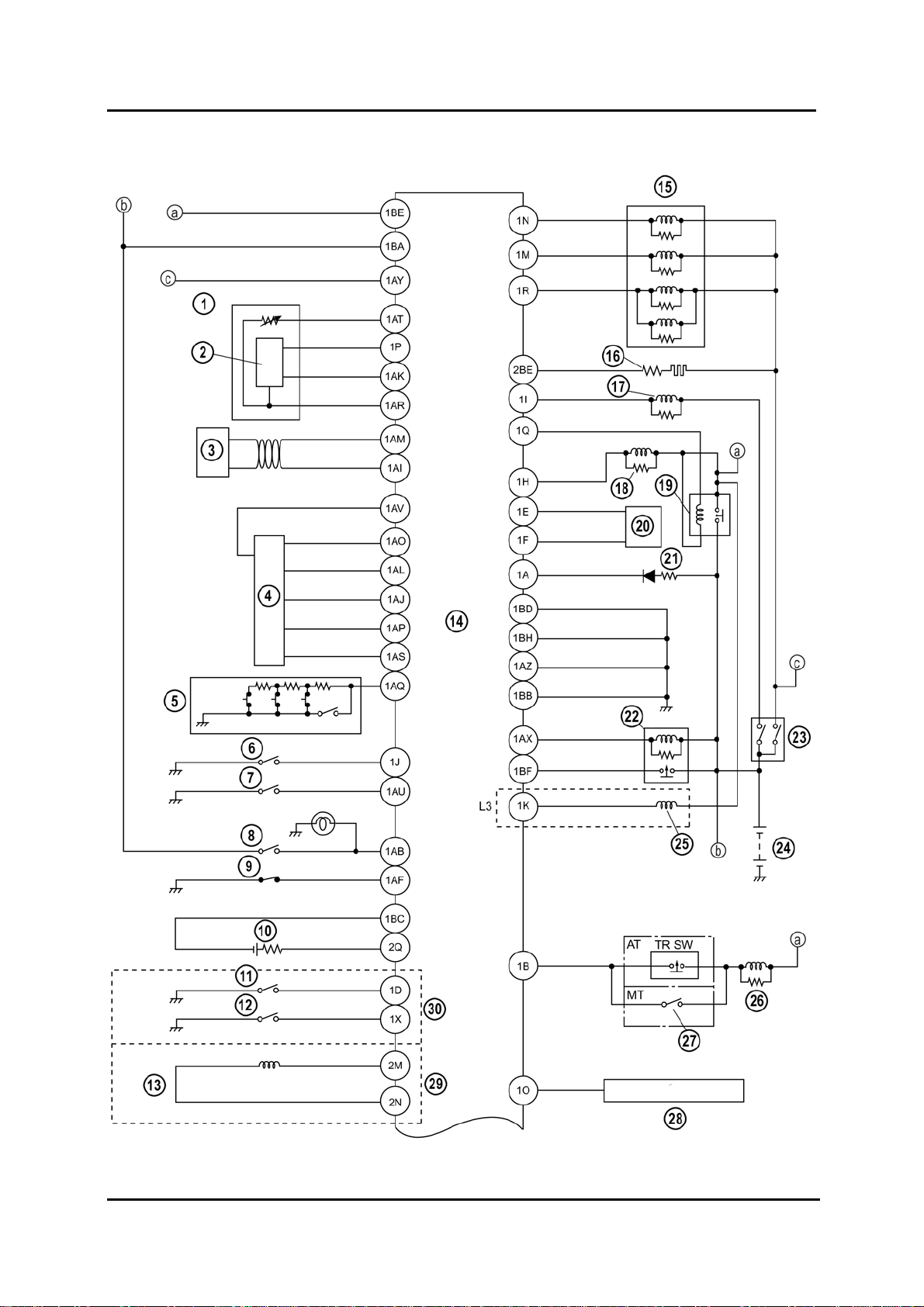
Wiring Diagram
M6FL_01014
01-14 Service Training Mazda6 Facelift

Engine Petrol Engines
1 IAT sensor 16 Rear HO2S heater
2 MAF sensor 17 A/C (Air Conditioning) relay
3 CAN 18 Fuel pump
4 APP sensor 19 Main relay
5 Cruise control switch 20 Coil antenna
6 Refrigerant pressure switch (medium) 21 Security light
7 Refrigerant pressure switch (high and low) 22 Drive-by-wire relay
8 Brake switch No.1 23 Ignition switch
9 Brake switch No.2 24 Battery
10
11
12
13
14
15
Rear HO2S 25 VAD solenoid valve
Clutch pedal position switch 26 Starter relay
Neutral switch 27 Starter interlock switch
VSS (Vehicle Speed Sensor) 28 VSS output signal
PCM 29 MTX without ABS/DSC
FAN relay 30 MTX
Service Training Mazda6 Facelift 01-15
Petrol Engines Engine
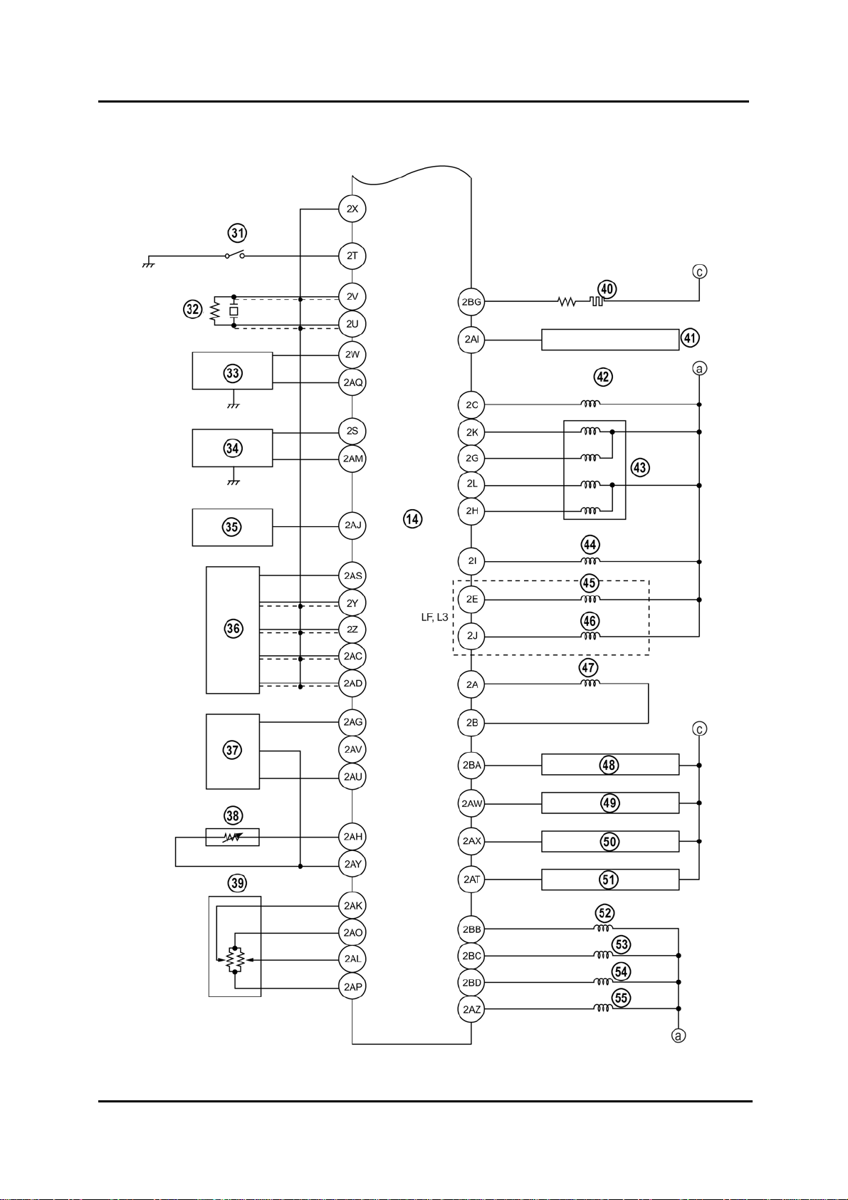
Wiring Diagram (Continued)
M6FL_01015
01-16 Service Training Mazda6 Facelift
 Loading...