

Mazda 1979-1984 RX7 Workshop Manual
This file is available for free download at http://www.iluvmyrx7.com
This file is fully text-searchable – select Edit and Find and type in what you’re looking
for. This file is intended more for online viewing than printing out so some graphics may
not print 100% legibly, you can zoom in on them if you need to.
www.iluvmyrx7.com
1.3L ENG NO START/BLOWN FUSE - SHORT IN WIRE HARNESS CAT. 15, NO. 012/85
Article Text
1983 Mazda RX7
For www.iluvmyrx7.com
Copyright © 1998 Mitchell Repair Information Company, LLC
ARTICLE BEGINNING
TECHNICAL SERVICE BULLETIN
APPLICATION
1979-84 RX7
SUBJECT
"ENGINE" Fuse Blows/No Start
REFERENCE
Mazda Motors Corp., Service Bulletin, No. 15 012/85, September, 1985
CONDITION & CAUSE
Monday, August 27, 2001 06:29AM
Some 1979-84 RX7 vehicles may exhibit an "ENGINE" fuse that blows,
preventing the engine from starting. This problem may be caused by an
electrical short circuit in the wiring harness.
REPAIR
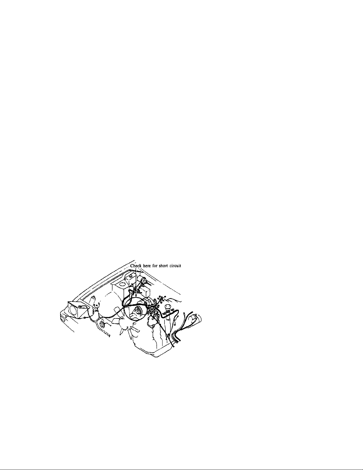
Check for a short circuit in the wire harness in the area of the
thermostat and air hose to the air cleaner. See Fig. 1.
Fig. 1: View of Wiring Harness
END OF ARTICLE

ACCEPTABLE BATTERY DRAIN CAT. 5, NO. 017/88
Article Text
1983 Mazda RX7
For www.iluvmyrx7.com
Copyright © 1998 Mitchell Repair Information Company, LLC
ARTICLE BEGINNING
Monday, August 27, 2001 06:29AM
TECHNICAL SERVICE BULLETIN
CURRENT DRAW FROM THE BATTERY
Model: All Models
Bulletin No.: 017/88
Date: 7/27/88
Category: 5
DESCRIPTION
In order to maintain the memory of the electrical equipment such as
radio, clock, and several other control units, a small amount of
current is drawn from the battery even though the vehicle is not in
use. Although the actual current may vary according to the electrical
equipment in each vehicle, the following specification can be used to
determine if the current draw of the vehicle in question is normal or
not.
CURRENT DRAW AMPERAGE
All Vehicles: 15 to 25 mA (Ignition key is removed or in the lock
position).
NOTE:
If the ignition key is in the ACC position, up to 250 mA is drawn from
the battery. This current draw is large enough to discharge the
battery in a few days.
TEST PROCEDURES
1. Turn the ignition switch off and remove the key from the cylinder.
2. Turn off all electrical loads. Make sure all doors and the trunk
lid are completely closed.
3. Open the hood and disconnect the negative battery terminal.
NOTE:
If the vehicle is equipped with theft-deterrent system, disconnect the
coupler from the hood switch so that the warning light of the theftdeterrent system is not operable.
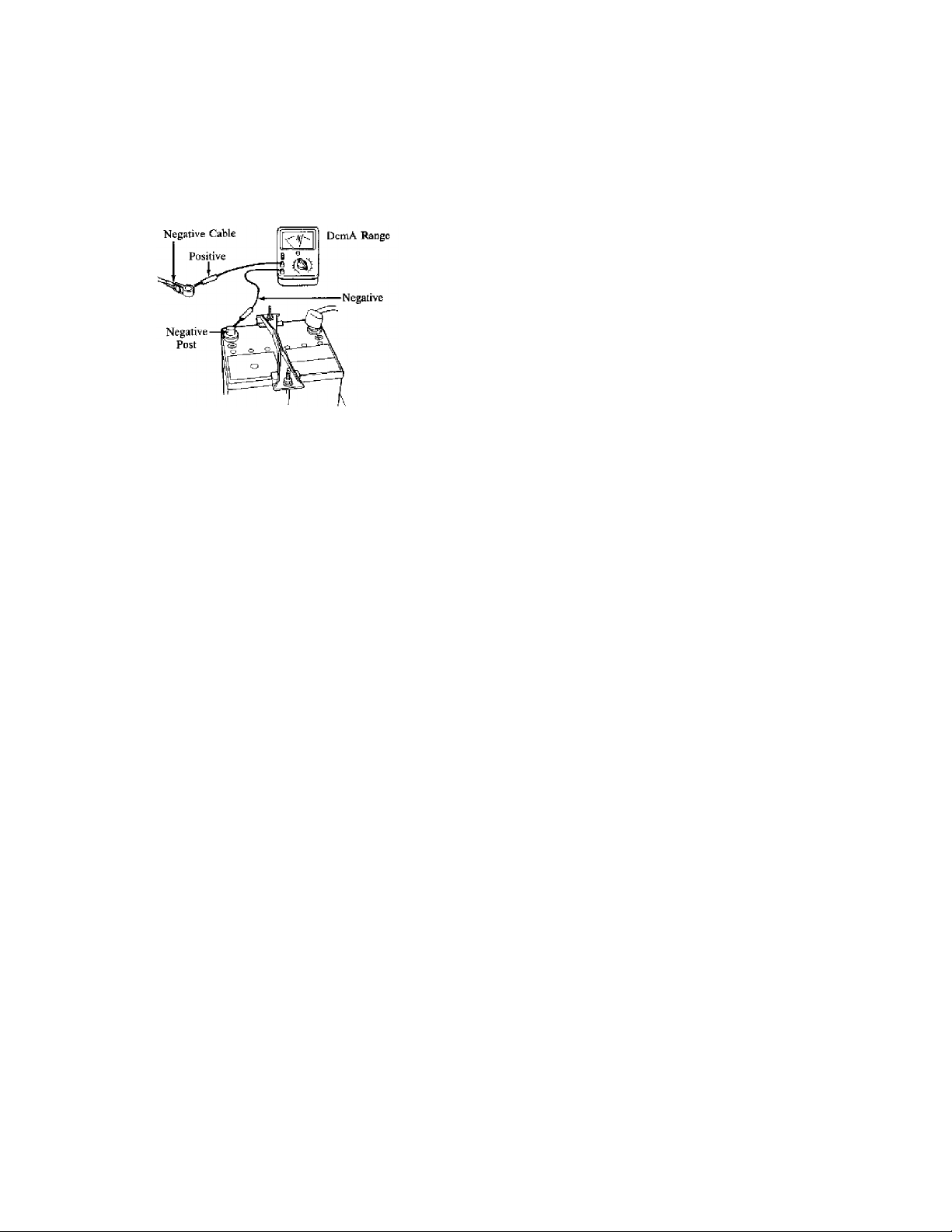
4. Set the circuit tester to the "DC mA" range, to at least 100 mA
range and check the current as follows:
Positive lead from tester to Negative Battery Cable
Negative lead from tester to Negative Battery Post.
CAUTION:
Do not open the door while checking the current, as the tester will be
ACCEPTABLE BATTERY DRAIN CAT. 5, NO. 017/88
For www.iluvmyrx7.com
Copyright © 1998 Mitchell Repair Information Company, LLC
Monday, August 27, 2001 06:29AM
damaged by the excessive current.
Fig. 1: Testing Currant Draw
END OF ARTICLE
Article Text (p. 2)
1983 Mazda RX7
ALTERNATOR/REGULATOR TEST PROCESS/REPLACEMENT INFO CAT. 5, NO. 058/83
Article Text
1983 Mazda RX7
For www.iluvmyrx7.com
Copyright © 1998 Mitchell Repair Information Company, LLC
ARTICLE BEGINNING
Monday, August 27, 2001 06:30AM
TECHNICAL SERVICE BULLETIN
IC REGULATOR CHECKING PROCEDURE
Models All Models
Bulletin No. 058/83
Category 5
Date 11/9/83
DESCRIPTION
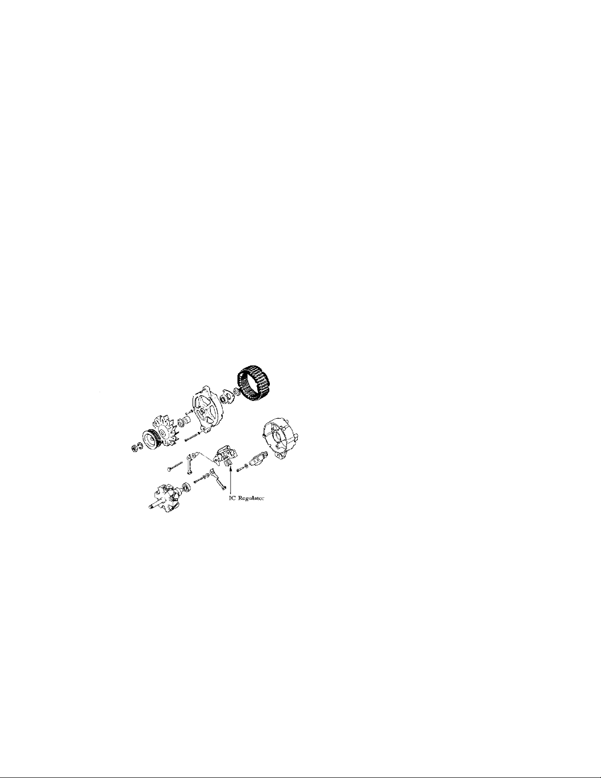
Checking procedure for the built-in IC regulator has been
established to pin point the alternator problem. Basically, the
alternator should be replaced as a unit through the exchange program.
However, in case of a shortage of refurbished alternators, you may
replace the IC regulator to minimize inconvenience of customers (see
Fig. 1).
Fig. 1: Exploded View of Alternator
PARTS INFORMATION
Regulator N221 24 520
CHECKING PROCEDURE
1. Make sure the battery is fully charged.
2. Turn ignition key on to "Ig" position. If the alternator warning
light is "off", the problem is likely to be caused by regulator.
Leave the key in "Ig" position and take the following step to
assure the cause.
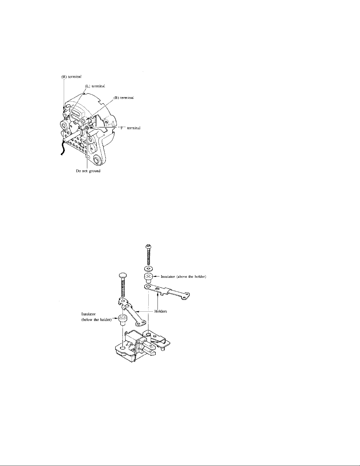
3. Insert volt meter between "F" terminal and nearest ground point
(Fig. 2).
4. Do not ground to the body of the alternator while positive probe
of voltmeter is inserted through the hole for "F" terminal.
ALTERNATOR/REGULATOR TEST PROCESS/REPLACEMENT INFO CAT. 5, NO. 058/83
For www.iluvmyrx7.com
Copyright © 1998 Mitchell Repair Information Company, LLC
Monday, August 27, 2001 06:30AM
Fig. 2: Location of "F" Terminal
REPAIR PROCEDURE
Article Text (p. 2)
1983 Mazda RX7
Please refer to the Service Information for IC regulator replacing
procedure.
NOTE: Be sure the insulators are in the proper position as shown in
Fig. 3.
Fig. 3: Proper Location of Insulators
END OF ARTICLE

AUDIO SYSTEM TROUBLESHOOTING PROCEDURES CAT. 15, NO. 078/89
Article Text
1983 Mazda RX7
For www.iluvmyrx7.com
Copyright © 1998 Mitchell Repair Information Company, LLC
ARTICLE BEGINNING
Monday, August 27, 2001 06:30AM
TECHNICAL SERVICE BULLETIN
AUDIO SYSTEM TROUBLESHOOTING
Model All Mazda Models
Category 15, Body Electrical System
Bulletin No. 078/89
Date May 5, 1989
DESCRIPTION
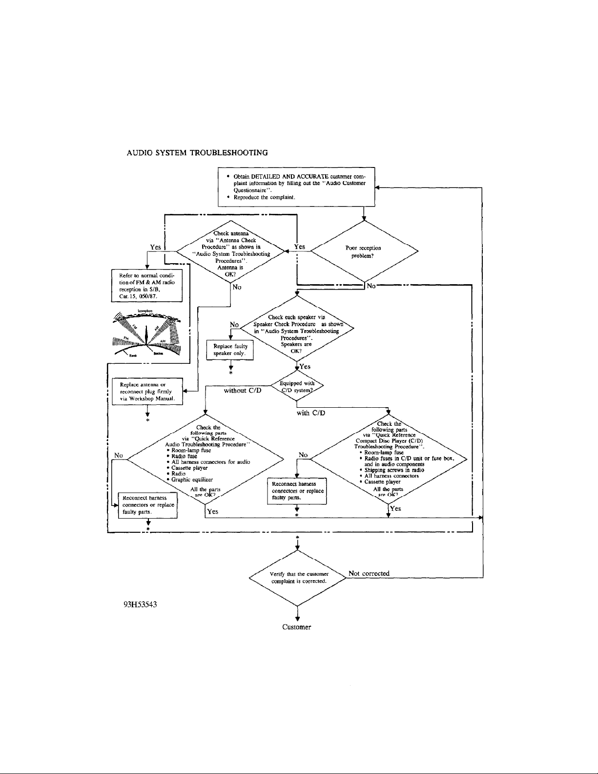
To simplify audio system troubleshooting, a flow chart (see Fig. 1)
has been prepared. It contains essentials of audio system troubleshooting procedures, focusing on the following:
* Obtain accurate information of customer's complaint.
* Carry out appropriate diagnosis or troubleshooting to find the
faulty part.
* Avoid replacing unnecessary parts.
* Verify whether the customer's complaint results from specific
characteristics of FM radio waves. If so, the complaint cannot be
corrected by audio component replacement.
Use the following materials with the attached flow chart when
carrying out inspection and repair of the audio system.
* Audio System Troubleshooting Procedures (plastic sheet)
* Service Bulletin, Category 15, 050/87 (FM Reception)
* Audio Customer Questionnaire
* Workshop Manual
NOTE: If it becomes necessary to disconnect power to the audio
system, be sure to copy down the customer's preset stations.
Re-set these stations after repairs are complete.
AUDIO SYSTEM TROUBLESHOOTING PROCEDURES CAT. 15, NO. 078/89
Article Text (p. 2)
1983 Mazda RX7
For www.iluvmyrx7.com
Copyright © 1998 Mitchell Repair Information Company, LLC
Monday, August 27, 2001 06:30AM
Fig. 1: Audio System Troubleshooting
END OF ARTICLE
BATTERY REMOVAL/INSTALL WIRE CLIP WARNING CAT. 14, NO. 009/85
Article Text
1983 Mazda RX7
For www.iluvmyrx7.com
Copyright © 1998 Mitchell Repair Information Company, LLC
ARTICLE BEGINNING
Monday, August 27, 2001 06:31AM
TECHNICAL SERVICE BULLETIN
BATTERY CLAMP BOLT & NUT
Models RX-7
Bulletin No. 009/85
Category 14
Date 1/22/85
DESCRIPTION
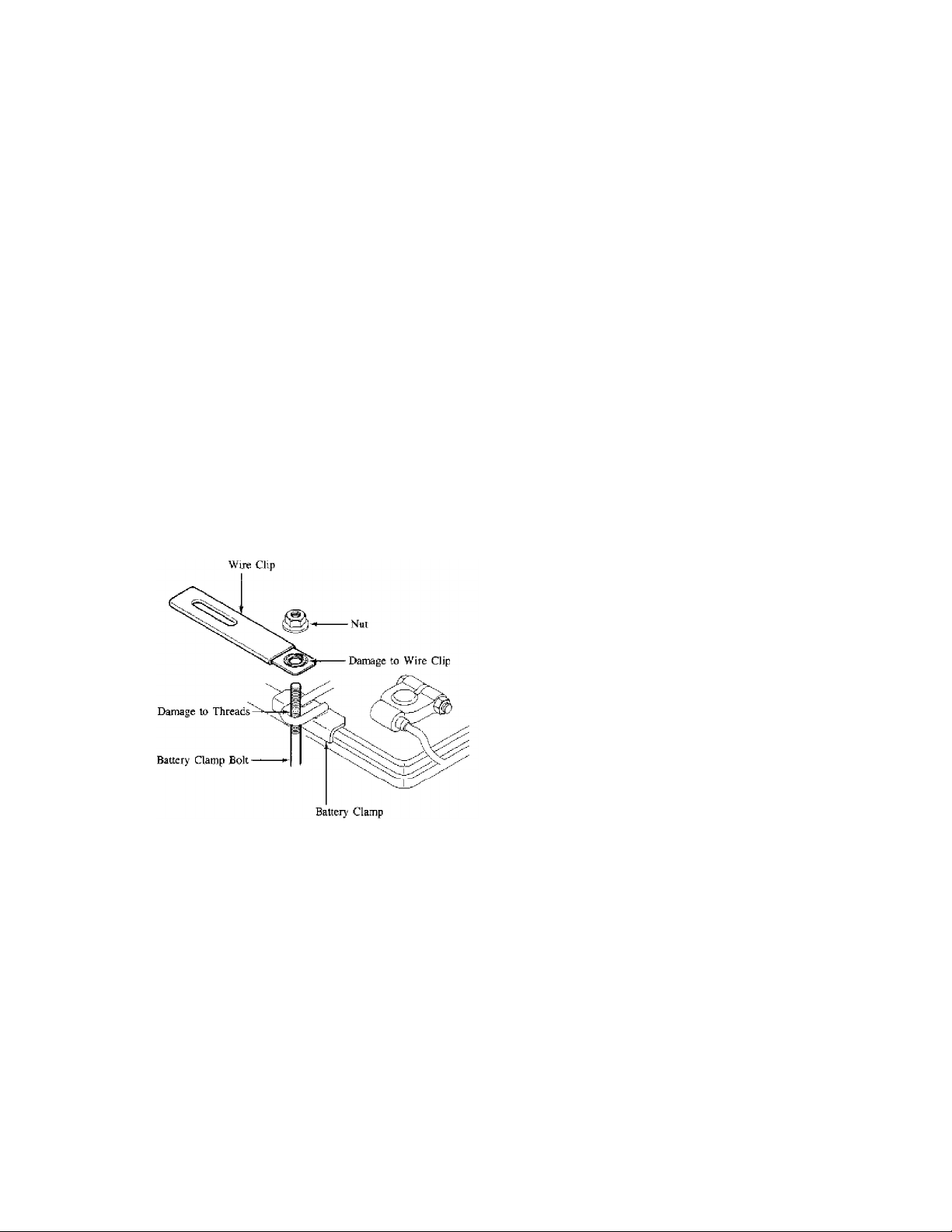
During installation of the battery clamp rod and nut, it is possible
for wire clip to become pinched in the threads on the clamp bolt,
resulting in the nut binding on the clamp rod. See Fig. 1.
If you encounter this problem, please follow the repair procedure
below.
Fig. 1: Battery Clamp Bolt & Nut
PARTS INFORMATION
ДДДДДДДДДДДДДДДДДДДДДДДДДДДДДД
PART NUMBER DESCRIPTION
0613 65 857A Clamp Bolt
9994 00 602 Nut
ДДДДДДДДДДДДДДДДДДДДДДДДДДДДДД
REPAIR PROCEDURE
1. Carefully remove the nut from the battery clamp bolt.
2. Use a die to repair the threads on the clamp bolt.
3. Install a small washer on top of the wire clip to prevent damage
to the threads on the clamp bolt during reinstallation.
END OF ARTICLE

FUSIBLE LINK REFERENCE CHART NO. T-2-3
Article Text
1983 Mazda RX7
For www.iluvmyrx7.com
Copyright © 1998 Mitchell Repair Information Company, LLC
ARTICLE BEGINNING
Monday, August 27, 2001 06:31AM
TECHNICAL SERVICE BULLETIN
FUSIBLE LINK REFERENCE CHART
Model: All Mazda
Date: November 1, 1990 (Revised - April 27, 1992)
No: T-2-3
Group: Parts Bulletin
SERVICE INFORMATION
For easy reference, the following list of Fusible Links have been
compiled.
FUSIBLE LINK REFERENCE CHART
ДДДДДДДДДДДДДДДДДДДДДДДДДДДДДДДДДДДДДДДДДДДДДДДДДДДДДДДДДДД
Year Model Location P/N
ДДДДДДДДДДДДДДДДДДДДДДДДДДДДДДДДДДДДДДДДДДДДДДДДДДДДДДДДДДД
1979-82 626 Engine Compartment 8174-66-760B
1983-85 626 Gas Engine Compartment 3775-67-099
1983-85 626 Diesel Engine Compartment H047-67-099
1983-85 626 Alternator HA67-67-099
1979 RX-7 Under Dash 1175-66-710A
1980 RX-7 Under Dash 8130-66-710
1980 RX-7 Engine Compartment 8341-18-055
1981 RX-7 Under Dash FA02-67-099
1981-85 RX-7 Engine Compartment 3777-67-099
1981-85 RX-7 Transmission 8341-18-055
1981-85 RX-7 Engine Compartment 8871-67-099
1984-85 RX-7 Engine Compartment 3775-67-099
1981-85 GLC Engine Compartment B003-67-099
1981-85 GLC Engine Compartment B005-67-099
1981-85 GLC Engine Compartment B006-67-099
1977-82 B2000 Engine Compartment B094-67-099
1983-84 B2000/B2200 Engine Compartment UA47-66-099
1988-93 MX-6 Engine Compartment FB01-67-099
M/T,
Non-Turbo A/T
1988-93 626 Sedan Engine Compartment FB01-67-099
1988-93 626 Hatchback Engine Compartment FB01-67-099
M/T,
Non-Turbo A/T
1990-92 929, 929S Engine Compartment FB01-67-099
1986-92 323 Engine Compartment FB01-67-099
1987-89 323 Wagon Engine Compartment FB01-67-099
1986-91, 93 RX-7 Engine Compartment FB01-67-099

FUSIBLE LINK REFERENCE CHART NO. T-2-3
Article Text (p. 2)
1983 Mazda RX7
For www.iluvmyrx7.com
Copyright © 1998 Mitchell Repair Information Company, LLC
Monday, August 27, 2001 06:31AM
1992 MX-3 Engine Compartment FB01-67-099
1984-86 GLC Wagon Engine Compartment 8573-66-760
ДДДДДДДДДДДДДДДДДДДДДДДДДДДДДДДДДДДДДДДДДДДДДДДДДДДДДДДДДДД
END OF ARTICLE

HIGH PITCH BUZZING NOISE AT DASH: REMOVE OSCILLATOR
Article Text
1983 Mazda RX7
For www.iluvmyrx7.com
Copyright © 1998 Mitchell Repair Information Company, LLC
ARTICLE BEGINNING
Saturday, September 08, 2001 10:01AM
TECHNICAL INFORMATION TIP
BUZZING ROTARY
YEAR(S): 1979-85
MANUFACTURER: Mazda
MODEL(S): RX-7
ISSUE: HIGH PITCH BUZZING NOISE AT DASH - REMOVE OSCILLATOR
If you hear a high pitched buzzing noise coming from the center
of the dash with the key off on a 1979-85 Mazda RX-7, the cause may be
a defective oscillator. The oscillator is located under the hood, in
the area near the left headlight.
To stop the noise, unplug the oscillator. The oscillator is used
as a dash instrument circuit backup. Removing the oscillator has no
other effect except to stop the constant buzzing noise.
Courtesy of Import Service Magazine
with thanks to
James Halderman
Sinclair College
Dayton, Ohio
REFERENCE NUMBER: MAZ0170AP
NOTE: This information has been obtained from sources generally
believed to be reliable. Use your own judgment before relying
on this data. Neither the suppliers of these Technical
Information Tips, nor Mitchell International, guarantees or
assumes responsibility for data accuracy or completeness, nor
is liability assumed by the suppliers of these Technical
Information Tips or Mitchell International for any claims or
damages resulting from the use of this information.
END OF ARTICLE
KEYLESS SWITCH SPEED NUT INFORMATION CAT. 15, NO. 010/85
Article Text
1983 Mazda RX7
For www.iluvmyrx7.com
Copyright © 1998 Mitchell Repair Information Company, LLC
ARTICLE BEGINNING
Monday, August 27, 2001 06:32AM
TECHNICAL SERVICE BULLETIN
SPEED NUT FOR IGNITION KEY SWITCH
Models GLC, 626, RX-7 & B2000
Bulletin No. 010/85
Category 15
Date 6/25/85
DESCRIPTION
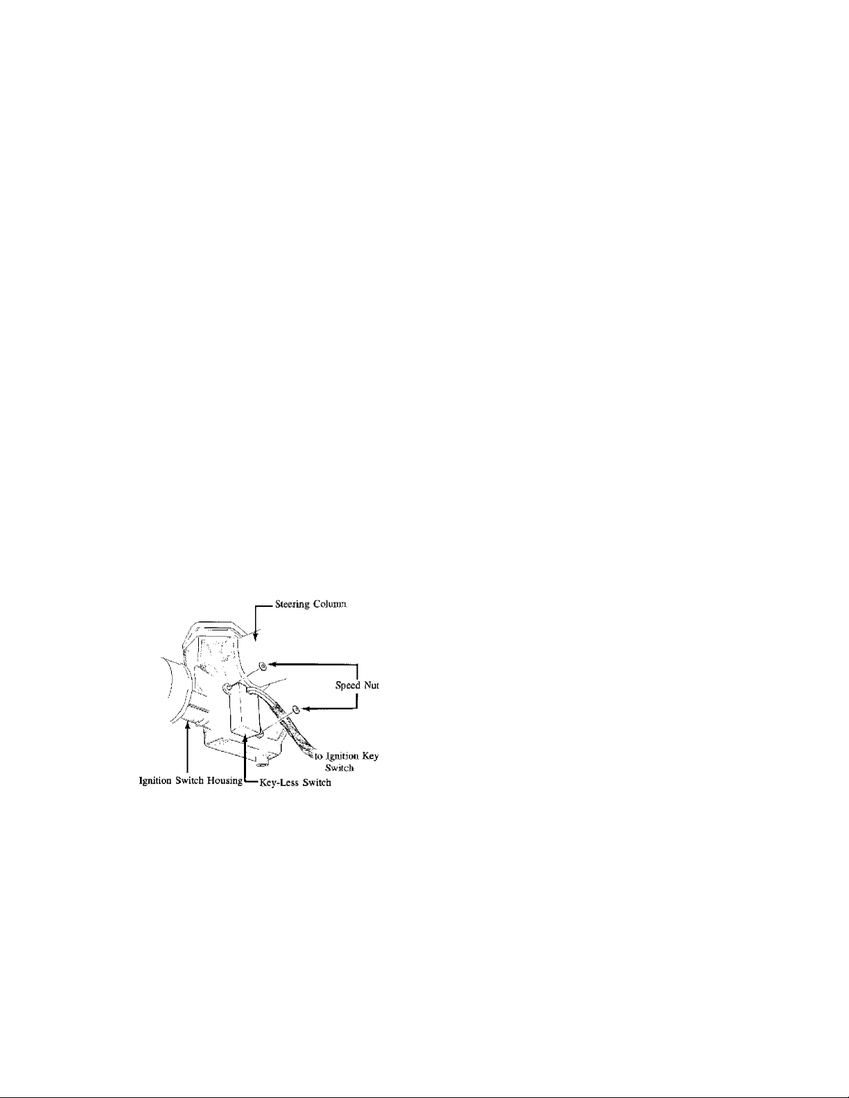
The speed nut for fixing the key-less switch to the ignition key
cylinder housing has been established as a service part. If the
replacement of the ignition key switch is necessary, please use the
new speed nut to secure the key-less switch. See Fig. 1.
PARTS INFORMATION
ДДДДДДДДДДДДДДДДДДДДДДДДДДДДДДДДДДДДДДДДДДДД
NEW PART NO. OLD PART NO. DESCRIPTION
BC46 66 158 ÄÄ Speed Nut
ДДДДДДДДДДДДДДДДДДДДДДДДДДДДДДДДДДДДДДДДДДДД
Fig. 1: Securing Key-Less Switch with Speed Nut
END OF ARTICLE
MISCELLANEOUS BLOWN FUSES/ELECTRICAL PROBLEMS CAT. 15, NO. 016/85
Article Text
1983 Mazda RX7
For www.iluvmyrx7.com
Copyright © 1998 Mitchell Repair Information Company, LLC
ARTICLE BEGINNING
Monday, August 27, 2001 06:32AM
TECHNICAL SERVICE BULLETIN
APPLICATION
1979-85 RX7
SUBJECT
Miscellaneous Blown Fuses/Electrical Problems
REFERENCE
Mazda Motors Corp., Service Bulletin, No. 15 016/85, October, 1985
CONDITION & CAUSE
Some 1979-85 RX7 vehicles may exhibit one or more of the following
electrical problems:
* RADIO, ANTENNA fuse blown
* TAIL, ILLUM fuse blown
* METER, BACK fuse blown
* OPENER fuse blown
* Inoperative rear defroster/rear wiper
* Rear wiper operates with wiper switch in OFF position
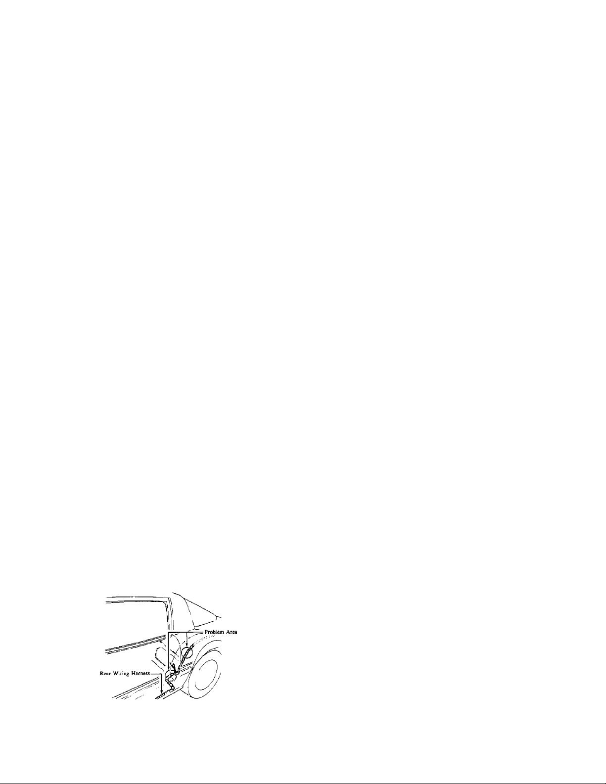
One or more of the above problems may be caused by a short circuit in
the rear harness. The rear harness may be cut by a sharp metal edge
where the harness is routed over the inner wheel well. See Fig. 1.
This was fixed in production beginning with VIN JM1FB33 F0852204.
REPAIR
If this problem is present, repair the rear harness as necessary.
Fig. 1: View of Rear Wiring Harness
END OF ARTICLE
REAR WINDOW DEFROSTER GRID LINE REPAIR PROCEDURE CAT. T, NO. 015/95
Article Text
1983 Mazda RX7
For www.iluvmyrx7.com
Copyright © 1998 Mitchell Repair Information Company, LLC
ARTICLE BEGINNING
Monday, August 27, 2001 06:33AM
TECHNICAL SERVICE BULLETIN
REAR WINDOW DEFROSTER GRID LINE REPAIR
Model(s): All Mazda Models
Category: T - Body Electrical System
Bulletin No.: 015/95
Date Issued: November 14, 1995
Date Revised: December 21, 1995
DESCRIPTION
The following procedure should be used to repair broken grid lines
on rear window defrosters. Place a copy of these procedures in the
appropriate section of the workshop manual.
REPAIR PROCEDURE
1. Turn the defroster switch on with the ignition in the on position.
2. Determine the broken grid line visually or with a test light or
voltage meter.
3. Turn the defroster and ignition Off.
4. Clean the area with a glass cleaner.
5. Remove the protective backing from the stencil.
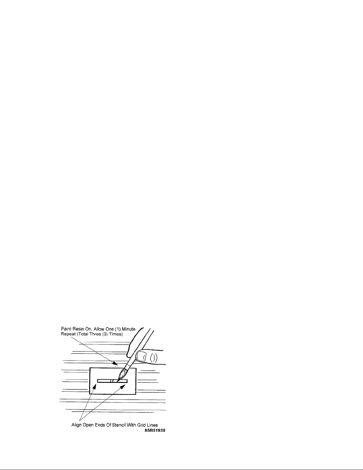
6. Align both ends of the broken grid line with the opening in the
stencil and press firmly to attach. See Fig. 1
Fig. 1: Resin Application Location

REAR WINDOW DEFROSTER GRID LINE REPAIR PROCEDURE CAT. T, NO. 015/95
Article Text (p. 2)
1983 Mazda RX7
For www.iluvmyrx7.com
Copyright © 1998 Mitchell Repair Information Company, LLC
Monday, August 27, 2001 06:33AM
NOTE: Make sure both ends are aligned prior to attaching.
7. Shake the bottle of resin well.
CAUTION: Continuity failure will occur if the ingredients are not
mixed completely.
8. Brush on the resin overlapping both ends of the broken grid line.
NOTE: Use paint remover to clean brush for future applications.
9. Repeat application (total of 3 times) when the surface is tack-free
(approximately one (1) minute).
10. Allow to dry twenty (20) minutes.
11. Carefully peel stencil from glass.
12. Allow twenty-four (24) hours before activating rear defroster.
PARTS INFORMATION
PARTS INFORMATION TABLE
ЪДДДДДДДДДДДДДДВДДДДДДДДДДДДД¿
³
Part Number ³ Description
ГДДДДДДДДДДДДДДЕДДДДДДДДДДДДД´
³
0000 88 5067 ³ Resin
АДДДДДДДДДДДДДДБДДДДДДДДДДДДДЩ
WARRANTY INFORMATION
³
³
(Applies To Verified Customer Complaints On Vehicles Covered Under
Normal Warranty. Refer To The SRT Microfiche For Warranty Term
Information.)
Warranty Type: A
Symptom Code: D5
Damage Code: AA
Part Number Main Cause: 0000 88 5067
Quantity: 0
Operation Number: XX0777RX
Labor Hours: 0.3 Hrs.
END OF ARTICLE
REVISED WIPER LINK BUSHING CAT. 14, NO. 022/85
Article Text
1983 Mazda RX7
For www.iluvmyrx7.com
Copyright © 1998 Mitchell Repair Information Company, LLC
ARTICLE BEGINNING
Monday, August 27, 2001 06:33AM
TECHNICAL SERVICE BULLETIN
WIPER LINK
Models 1981-1985 RX-7
Bulletin No. 022/85
Category 14
Date 10/18/85
DESCRIPTION
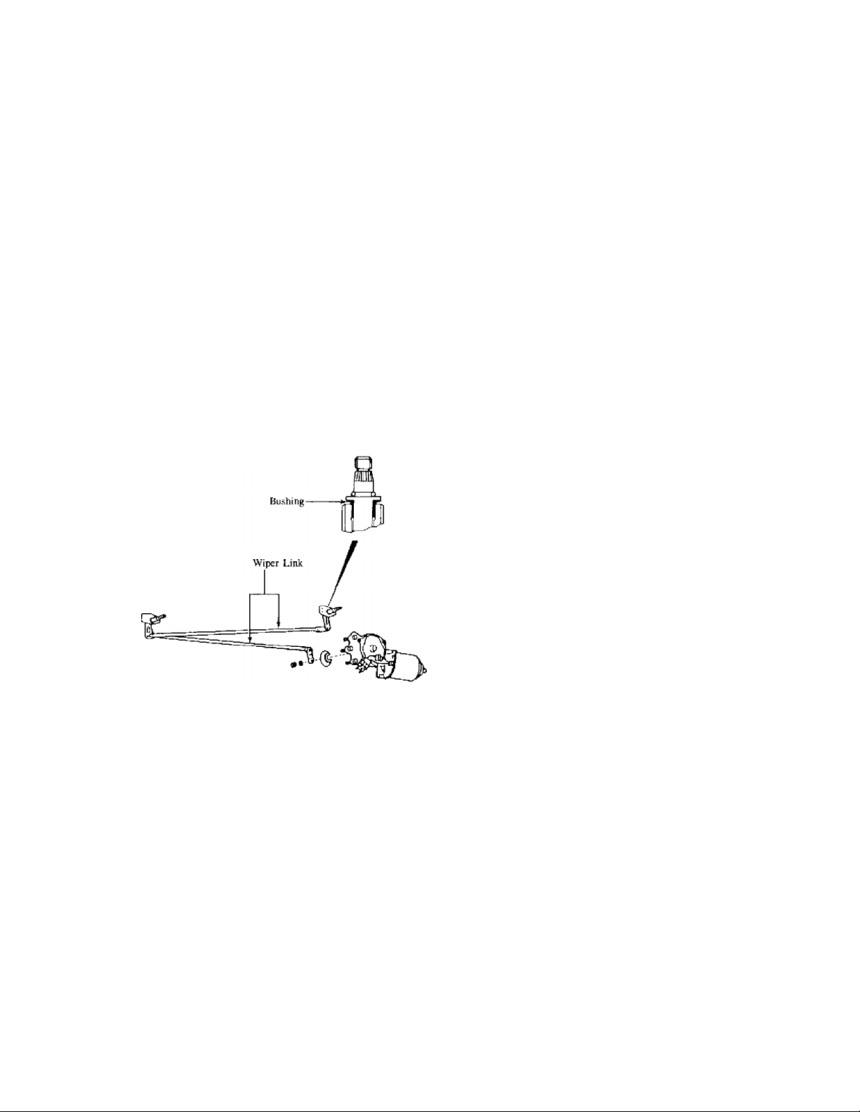
A new wiper link has been established as a service part. This new
wiper link features a bushing as shown in Fig. 1.
Fig. 1: 1981-85 RX7 Wiper Link
PARTS INFORMATION
ДДДДДДДДДДДДДДДДДДДДДДДДДДДДДДДДДДДДДДДДДДДДДДДДДДДДДДДДДДДДДДДДДДДДДД
NEW PART NO. OLD PART NO. DESCRIPTION INTERCHANGEABILITY APPLIED
MODEL
FA54 76 601A FA54 76 601 Wiper Link NEW -> OLD 1984-85 RX-7
8871 76 601B 8871 76 601A Wiper Link NEW -> OLD 1981-83 RX-7
ДДДДДДДДДДДДДДДДДДДДДДДДДДДДДДДДДДДДДДДДДДДДДДДДДДДДДДДДДДДДДДДДДДДДДД
NOTE: A new part can be used in place of the former part, but the
former part may not be used in place of the new part.
END OF ARTICLE
TURN SIGNAL DOESN'T CANCEL - REPLACE CANCEL CAM CAT. 14, NO. 010/85
Article Text
1983 Mazda RX7
For www.iluvmyrx7.com
Copyright © 1998 Mitchell Repair Information Company, LLC
ARTICLE BEGINNING
Monday, August 27, 2001 06:34AM
TECHNICAL SERVICE BULLETIN
TURN SIGNAL SWITCH CANCEL CAM
Models All Models
Bulletin No. 010/85
Category 14
Date 1/22/85
Symptom Turn Signal Doesn't Cancel
DESCRIPTION
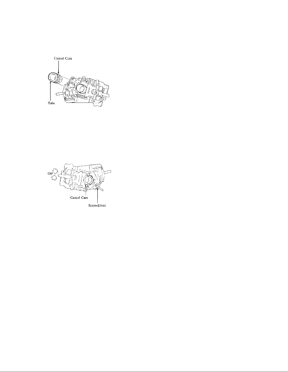
If the turn signal switch does not cancel, the most probable cause
is a broken cancel cam. The cancel cam is available separately and can
be replaced as shown below.
REPAIR PROCEDURE
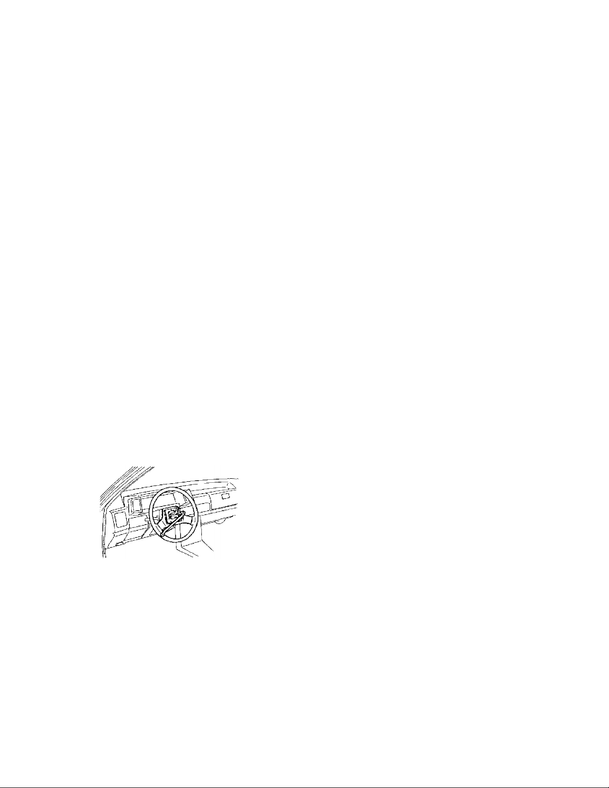
1. Put a mark on the steering wheel and steering shaft so that the
steering wheel can be reinstalled in the same position.
2. Remove the retaining nut for the steering wheel and remove the
steering wheel with a steering wheel puller. See Fig. 1.
CAUTION: Do not strike the steering shaft with a hammer as this will
damage the steering shaft.
Fig. 1: Steering Wheel Removal
3. Inspect the cancel cam. If the tabs are broken off the cancel
cam, the combination switch can be repaired by replacing the
cancel cam. See Fig. 2.
NOTE: It is not necessary to remove the combination switch to replace
the cancel cam.
TURN SIGNAL DOESN'T CANCEL - REPLACE CANCEL CAM CAT. 14, NO. 010/85
Article Text (p. 2)
1983 Mazda RX7
For www.iluvmyrx7.com
Copyright © 1998 Mitchell Repair Information Company, LLC
Monday, August 27, 2001 06:34AM
Fig. 2: Turn Signal Cancel Cam
4. Place the turn signal in the "OFF" position .
5. Carefully pry the cancel cam from the combination switch using a
screwdriver. See Fig. 3.
6. Install the new cancel cam to the combination switch.
NOTE: It is not necessary to apply additional grease to the cancel
cam.
Fig. 3: Removing Cancel Cam from Switch
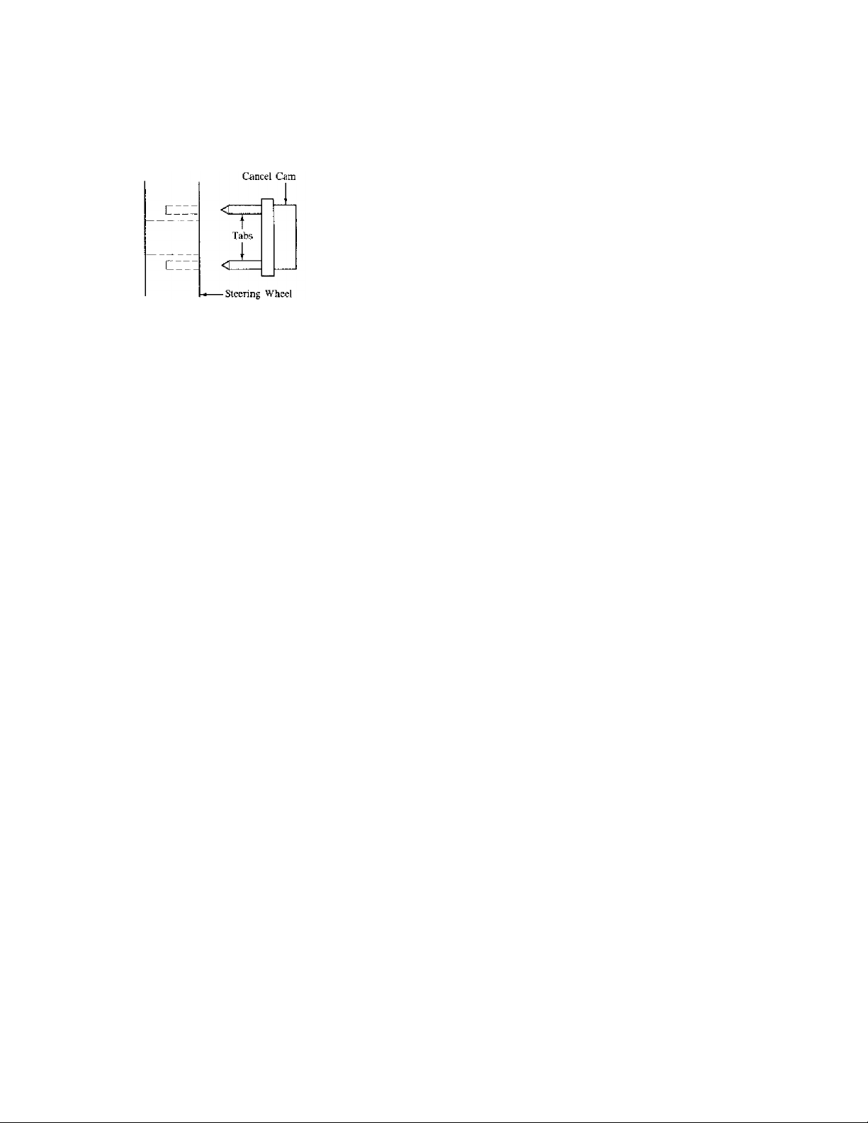
7. Align the tabs of the cancel cam with the holes in the steering
wheel and install the steering wheel.
NOTE: The cancel cam will be broken if the tabs are not aligned with
the holes in the steering wheel. See Fig. 4.
8. Install the steering wheel and torque the retaining nut to
specification.
TORQUE SPECIFICATION
ДДДДДДДДДДДДДДДДДДДДДДДДДДДДДДДД
Model Specification
RX-7, 626, GLC 29-36 ft-lb
B2000, B2200 22-29 ft-lb
ДДДДДДДДДДДДДДДДДДДДДДДДДДДДДДДД
TURN SIGNAL DOESN'T CANCEL - REPLACE CANCEL CAM CAT. 14, NO. 010/85
For www.iluvmyrx7.com
Copyright © 1998 Mitchell Repair Information Company, LLC
Monday, August 27, 2001 06:34AM
Fig. 4: Aligning Cancel Cam Tabs
END OF ARTICLE
Article Text (p. 3)
1983 Mazda RX7
1.2L ENG MODIFIED A/C COMPRESSOR BRACKET INSTRUCTION CAT. 15, NO. 124/83
Article Text
1983 Mazda RX7
For www.iluvmyrx7.com
Copyright © 1998 Mitchell Repair Information Company, LLC
ARTICLE BEGINNING
Monday, August 27, 2001 06:35AM
TECHNICAL SERVICE BULLETIN
A/C COMPRESSOR BRACKET INSTALLATION
Models 1983 RX-7
Bulletin No. 124/83
Category 15
Date 11/2/83
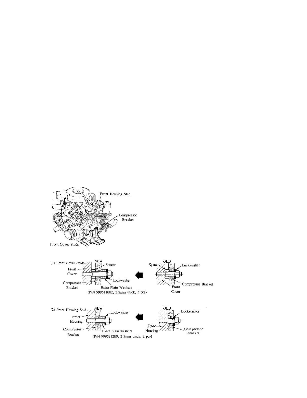
DESCRIPTION
The unthreaded portion of studs for air conditioner compressor
bracket has been extended for common use of the parts with other
models. Because of this change since the production date of September,
1983, it is necessary to insert plain washers between the bracket and
securing nuts in order to compensate for the extended length of the
studs.
Fig. 1: Installation of A/C Compressor Bracket
Fig. 2: Installation of A/C Compressor Bracket to Front Cover
Fig. 3: Installation of A/C Compressor Bracket to Front Housing
VIN OF PRODUCTION CHANGE
ДДДДДДДДДДДДДДДДДДДДДДДДДДДДДДДДДДДДДДДДДДДДДДДДДДДДДДДДДД
RX-7: JMIFB331 D0762194 September, 1983
ДДДДДДДДДДДДДДДДДДДДДДДДДДДДДДДДДДДДДДДДДДДДДДДДДДДДДДДДДД

1.2L ENG MODIFIED A/C COMPRESSOR BRACKET INSTRUCTION CAT. 15, NO. 124/83
Article Text (p. 2)
1983 Mazda RX7
For www.iluvmyrx7.com
Copyright © 1998 Mitchell Repair Information Company, LLC
Monday, August 27, 2001 06:35AM
PARTS INFORMATION
Plain washers are not included in the 1983 RX7 kits but will be in
1984. However, these washers will be available under the following
part numbers:
9995 11 022 (3.2mm, 6 pcs.) for Front Cover Stud.
9995 21 200 (2.3mm, 2 pcs.) for Front Housing Stud.
END OF ARTICLE
A/C LITE DIM/NOT ON - WIRE HARNESS CONNECTOR CAT. 16, NO. 008/85
Article Text
1983 Mazda RX7
For www.iluvmyrx7.com
Copyright © 1998 Mitchell Repair Information Company, LLC
ARTICLE BEGINNING
Monday, August 27, 2001 06:35AM
TECHNICAL SERVICE BULLETIN
AIR CONDITIONER INDICATOR LIGHT
Models RX-7
Bulletin No. 008/85
Category 16
Date 7/16/85
Symptom No A/C Light
DESCRIPTION
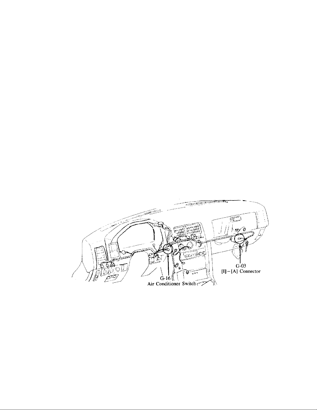
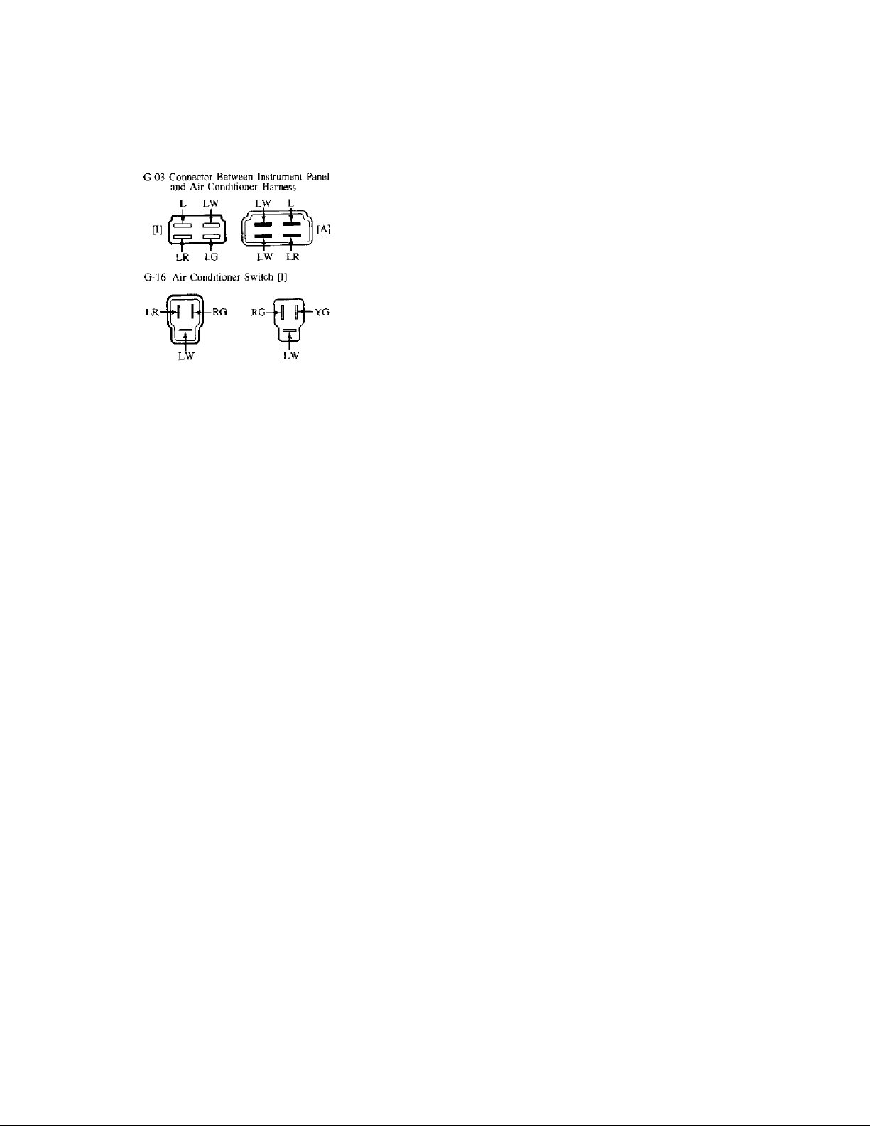
Some air conditioner kits manufactured by Lone Star Manufacturing
Company may contain incorrectly assembled harness connectors. If the
indicator light on the air conditioner switch does not illuminate. or
illuminates dimly after installation, the problem may be due to
incorrectly assembled G-03 or G-16 connectors. See Fig. 1.
Fig. 1: A/C Indicator Light Harness Routing
REPAIR PROCEDURE
1. Check that the G-03 accessory connector (A) is assembled
correctly as viewed from the harness side of the connector.
If not, remove the incorrect terminals and reassemble according
to the connector diagram.
2. Check that the G-16 accessory connector (A) is assembled
correctly as viewed from the harness side of the connector.
If not, remove the incorrect terminals and reassemble according
to the connector diagram. See Fig. 2.
A/C LITE DIM/NOT ON - WIRE HARNESS CONNECTOR CAT. 16, NO. 008/85
Article Text (p. 2)
1983 Mazda RX7
For www.iluvmyrx7.com
Copyright © 1998 Mitchell Repair Information Company, LLC
Monday, August 27, 2001 06:35AM
Fig. 2: RX7 A/C Accessory Connectors
END OF ARTICLE
CORRECT FREON CHARGE WARNING SPECS CAT. 16, NO. 034/88
Article Text
1983 Mazda RX7
For www.iluvmyrx7.com
Copyright © 1998 Mitchell Repair Information Company, LLC
ARTICLE BEGINNING
Monday, August 27, 2001 06:36AM
TECHNICAL SERVICE BULLETIN
REFRIGERANT CHARGE SERVICE
Model: ALL MODELS WITH A/C
Bulletin No.: 034/88
Date: 6/30/88
Category: 16
DESCRIPTION
To insure proper and efficient operation of the Air Conditioning
System, it is of extreme importance to verify that the Air
Conditioning System is properly charged. Also, please note that overcharging the Air Conditioning system can cause higher than normal
system pressures which could result in Air Conditioning System
component damage.
The recommended refrigerant charge for 1988 Mazda vehicles is as
follows:
323, RX-7, B-Series Truck...............................28 ounces
626, MX-6...............................................35 ounces
929.....................................................39 ounces
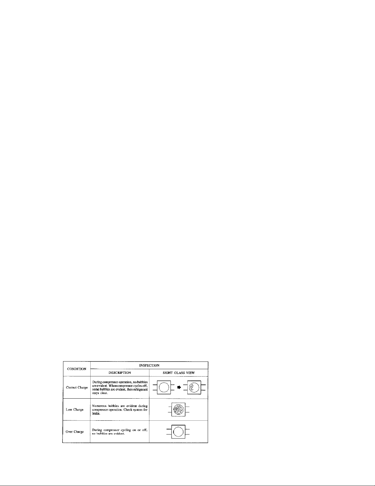
QUICK VISUAL CHECK
It is possible to make a quick visual check of the Air Conditioning
System to verify the correct refrigerant charge.
1) Run the engine as fast idle.
2) Operate the Air Conditioning System at maximum cooling for
approximately 5 minutes.
3) Observe the sight glass and compare to the possible results as
shown in Fig. 1.
Fig. 1: A/C Charging Sight Glass Symptoms

HEATING SYSTEM TROUBLESHOOTING CAT. U, NO. 93-04
Article Text
1983 Mazda RX7
For www.iluvmyrx7.com
Copyright © 1998 Mitchell Repair Information Company, LLC
ARTICLE BEGINNING
Monday, August 27, 2001 06:36AM
TECHNICAL SERVICE BULLETIN
HEATING SYSTEM TROUBLESHOOTING MANUAL
Model All Mazda Models
Category U
Bulletin No. 93-04
Date September, 1993
DESCRIPTION
This Service Bulletin contains a new Heating System Troubleshooting
Manual that was developed by the Mazda Canada Quality Assurance
Section. The diagnostic procedures were developed and tested in
Canada during a Cold Weather Test that took place in February 1993.
The diagnostic procedures were tested on vehicles in which customers
had complained about a lack of heat for several winters. The
effectiveness of these procedures was confirmed.
SPECIAL NOTE
This same manual will also be used as a hand out for all forth coming
Training Courses on Climate Control Systems.
HEATER AND DEFROSTER TROUBLESHOOTING MANUAL
INTRODUCTION
An investigation was conducted using customer vehicles at dealer-ships
across North America over a two year period. The investigation was
conducted to determine if there were any concerns that were difficult
to repair using existing Mazda repair manuals.
The following list represents items most commonly left unrepaired or
undiagnosed by the dealer.
1. Air leakage between the blower unit and the cooler unit.
2. Missing or mis-installed sealing grommets in the firewall.
3. Incorrect operation of the thermostat.
4. Improper usage of the recirculation and fresh air mode of the
ventilation system.
In order to assist in the correct diagnosis and repair of Heating
System concerns the following troubleshooting manual was developed.
See Fig. 1. for a visual description of the Climate Control System.

HEATING SYSTEM TROUBLESHOOTING CAT. U, NO. 93-04
Article Text (p. 2)
1983 Mazda RX7
For www.iluvmyrx7.com
Copyright © 1998 Mitchell Repair Information Company, LLC
Monday, August 27, 2001 06:36AM
Fig. 1: Climate Control System
USING THIS MANUAL
Follow the flow charts and diagnostic procedures below to repair the
complaints which were determined on the Customer Comment Sheet.
³ 1. Complete customer
³ comment sheet.
ЪДДДДДДДДДДДДДДДДДБДДДДДДДДДДДДДДДД¿
³ 2. Determine Nature of complaint
³ a) problem or b) improper usage
ЪДДДДДДДДДДБДДДДДДДДДДДДДД¿
АДДДДДДДДДДДДДДДДДВДДДДДДДДДДДДДДДДЩ
ЪДДДДДДДДДДДДДДДДДДДБДДДДДДДДДДДДДДДДДДДД¿
ЪДДДДДДДДДДДДДДДДДДДДДД¿
³
³
АДДДДДДДДДДДВДДДДДДДДДДЩ
ЪДДДДДДДДДДДДДДБДДДДДДДДД¿
³
³
³ 3a. Use diagnostic flow ³ ³ 3b. Instruct on proper
³ chart to determine ³ ³ system usage.
³ repair procedure. ³
³ 4. Use check sheet to
³ perform repairs.
АДДДДДДДДДДВДДДДДДДДДДДДДДЩ
ЪДДДДДДДДДДБДДДДДДДДДДДД¿
³
³
АДДДДДДДДДДДДДДДДДДДДДДДЩ
АДДДДДДДДДДДДДДДДДДДДДДДДЩ
³
³
Diagnostic Procedures

HEATING SYSTEM TROUBLESHOOTING CAT. U, NO. 93-04
Article Text (p. 3)
1983 Mazda RX7
For www.iluvmyrx7.com
Copyright © 1998 Mitchell Repair Information Company, LLC
Monday, August 27, 2001 06:36AM
1. Collect detailed complaint information from the customer using
the Customer Comment Sheet.
2. Use the information collected on the Customer Comment Sheet to
determine the nature of the complaint.
3a. Refer to the diagnostic flow chart and determine the necessary
checks.
3b. After determining the complaint is of a usage nature instruct
the customer on the proper operation of the system.
4. Use the Check Sheet to perform the necessary repairs.
ДДДДДДДДДДДДДДДДДДДДДДДДДДДДДДДДДДДДДДДДДДДДДДДДДДДДДДДДДДДДДДДДДДДДДД
CUSTOMER COMMENT SHEET
Please complete the following with the aid of the customer.
1. Heater Concern
ДДДДВДДДДДДДДДДДДДДДДДДДДДДДДДДДДДДДДДДДВДДДДДДДДДВДДДДДДДДДДДДДДДДДДД
No. ³ Customer Comment ³ Checked ³ Result
ДДДДЕДДДДДДДДДДДДДДДДДДДДДДДДДДДДДДДДДДДЕДДДДДДДДДЕДДДДДДДДДДДДДДДДДДД
1 ³ Water temp indicator reads low at ³
³ high speed ³
ДДДДЕДДДДДДДДДДДДДДДДДДДДДДДДДДДДДДДДДДДЕДДДДДДДДДЕДДДДДДДДДДДДДДДДДДД
2 ³ While driving the interior temp. ³
³ is cooler than when parked ³
ДДДДЕДДДДДДДДДДДДДДДДДДДДДДДДДДДДДДДДДДДЕДДДДДДДДДЕДДДДДДДДДДДДДДДДДДД
3 ³ Heater outlet air temperature is ³
³ always cold ³
ДДДДЕДДДДДДДДДДДДДДДДДДДДДДДДДДДДДДДДДДДЕДДДДДДДДДЕДДДДДДДДДДДДДДДДДДД
4 ³ Passenger side is cooler than ³
³ driver's side ³
ДДДДЕДДДДДДДДДДДДДДДДДДДДДДДДДДДДДДДДДДДЕДДДДДДДДДЕДДДДДДДДДДДДДДДДДДД
5 ³ Passenger feels cold air at feet ³
ДДДДЕДДДДДДДДДДДДДДДДДДДДДДДДДДДДДДДДДДДЕДДДДДДДДДЕДДДДДДДДДДДДДДДДДДД
6 ³ After vehicle interior has ³
³ reached normal temperature cool ³
³ air is felt at body ³
ДДДДЕДДДДДДДДДДДДДДДДДДДДДДДДДДДДДДДДДДДЕДДДДДДДДДЕДДДДДДДДДДДДДДДДДДД
7 ³ Upper body is cooler than foot ³
ДДДДЕДДДДДДДДДДДДДДДДДДДДДДДДДДДДДДДДДДДЕДДДДДДДДДЕДДДДДДДДДДДДДДДДДДД
8 ³ Temperature is unbalanced between ³
³ driver's and passenger's side ³
ДДДДБДДДДДДДДДДДДДДДДДДДДДДДДДДДДДДДДДДДБДДДДДДДДДБДДДДДДДДДДДДДДДДДДД
³
³
³
³
³
³
³
³
³
³
³
³
³
³
³
2. Defroster Concern
ДДДДВДДДДДДДДДДДДДДДДДДДДДДДДДДДДДДДДДДДВДДДДДДДДДВДДДДДДДДДДДДДДДДДДД
1 ³ At cold temperatures or high ³
³

HEATING SYSTEM TROUBLESHOOTING CAT. U, NO. 93-04
Article Text (p. 4)
1983 Mazda RX7
For www.iluvmyrx7.com
Copyright © 1998 Mitchell Repair Information Company, LLC
Monday, August 27, 2001 06:36AM
³ humidity the windows never clear ³
³ (all) ³
ДДДДЕДДДДДДДДДДДДДДДДДДДДДДДДДДДДДДДДДДДЕДДДДДДДДДЕДДДДДДДДДДДДДДДДДДД
2 ³ Even after reaching normal ³
³ operating temp. the front wind- ³
³ shield is only cleared 30-50 % ³
ДДДДЕДДДДДДДДДДДДДДДДДДДДДДДДДДДДДДДДДДДЕДДДДДДДДДЕДДДДДДДДДДДДДДДДДДД
3 ³ Rear window does not clear ³
ДДДДЕДДДДДДДДДДДДДДДДДДДДДДДДДДДДДДДДДДДЕДДДДДДДДДЕДДДДДДДДДДДДДДДДДДД
4 ³ Rear window clears only in the ³
³ middle ³
ДДДДБДДДДДДДДДДДДДДДДДДДДДДДДДДДДДДДДДДДБДДДДДДДДДБДДДДДДДДДДДДДДДДДДД
³
³
³
³
³
³
³
³
3. Temperature Control Concern
ДДДДВДДДДДДДДДДДДДДДДДДДДДДДДДДДДДДДДДДДВДДДДДДДДДВДДДДДДДДДДДДДДДДДДД
1 ³ Difficult to set temperature ³
ДДДДЕДДДДДДДДДДДДДДДДДДДДДДДДДДДДДДДДДДДЕДДДДДДДДДЕДДДДДДДДДДДДДДДДДДД
2 ³ Temperature unbalance between ³
³ head and foot ³
ДДДДЕДДДДДДДДДДДДДДДДДДДДДДДДДДДДДДДДДДДЕДДДДДДДДДЕДДДДДДДДДДДДДДДДДДД
3 ³ Temperature unbalance between ³
³ driver and passenger seat ³
ДДДДБДДДДДДДДДДДДДДДДДДДДДДДДДДДДДДДДДДДБДДДДДДДДДБДДДДДДДДДДДДДДДДДДД
³
³
³
³
³
4. Other Concerns
ДДДДВДДДДДДДДДДДДДДДДДДДДДДДДДДДДДДДДДДДВДДДДДДДДДВДДДДДДДДДДДДДДДДДДД
1 ³ ³
ДДДДЕДДДДДДДДДДДДДДДДДДДДДДДДДДДДДДДДДДДЕДДДДДДДДДЕДДДДДДДДДДДДДДДДДДД
2 ³ ³
ДДДДЕДДДДДДДДДДДДДДДДДДДДДДДДДДДДДДДДДДДЕДДДДДДДДДЕДДДДДДДДДДДДДДДДДДД
3 ³ ³
ДДДДБДДДДДДДДДДДДДДДДДДДДДДДДДДДДДДДДДДДБДДДДДДДДДБДДДДДДДДДДДДДДДДДДД
³
³
³
Record in the appropriate column if the item was checked and the
result.
ДДДДДДДДДДДДДДДДДДДДДДДДДДДДДДДДДДДДДДДДДДДДДДДДДДДДДДДДДДДДДДДДДДДДДД
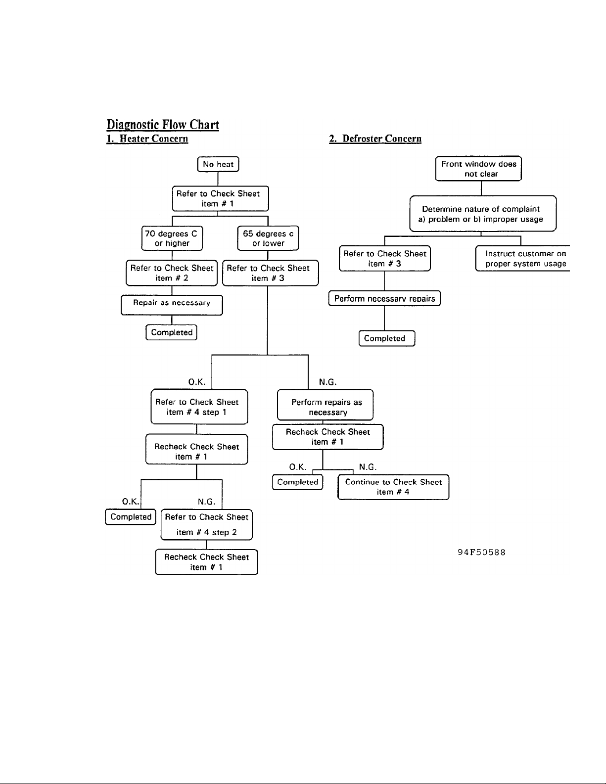
1. Heater Concern - Use the Diagnostic Flow Chart (see Fig. 2) to
determine the necessary diagnostic checks.
Refer to the Check Sheet.
HEATING SYSTEM TROUBLESHOOTING CAT. U, NO. 93-04
Article Text (p. 5)
1983 Mazda RX7
For www.iluvmyrx7.com
Copyright © 1998 Mitchell Repair Information Company, LLC
Monday, August 27, 2001 06:36AM
Fig. 2: Diagnostic Flow Chart
CHECK SHEET
Heater concern
Item 1: Measuring Vent Outlet Air Temperature
1. Place transmission in park or place manual transmission in
neutral and set the parking brake.
2. Start the engine and let idle until the engine reaches normal
operating temperatures.
 Loading...