

Mazda 0000-8F-Z80, 0000-8F-P07 Instructions Manual
GENUINE Mazda Mobile Start
INSTALLATION INSTRUCTIONS
Thank you for purchasing a genuine Mazda accessory.
Before removal and installation, be sure to thoroughly read these instructions. Please read the contents of this
booklet in order to properly install and use the Mazda Mobile Start. Your safety depends on it.
Keep these instructions with your vehicle records for future reference.
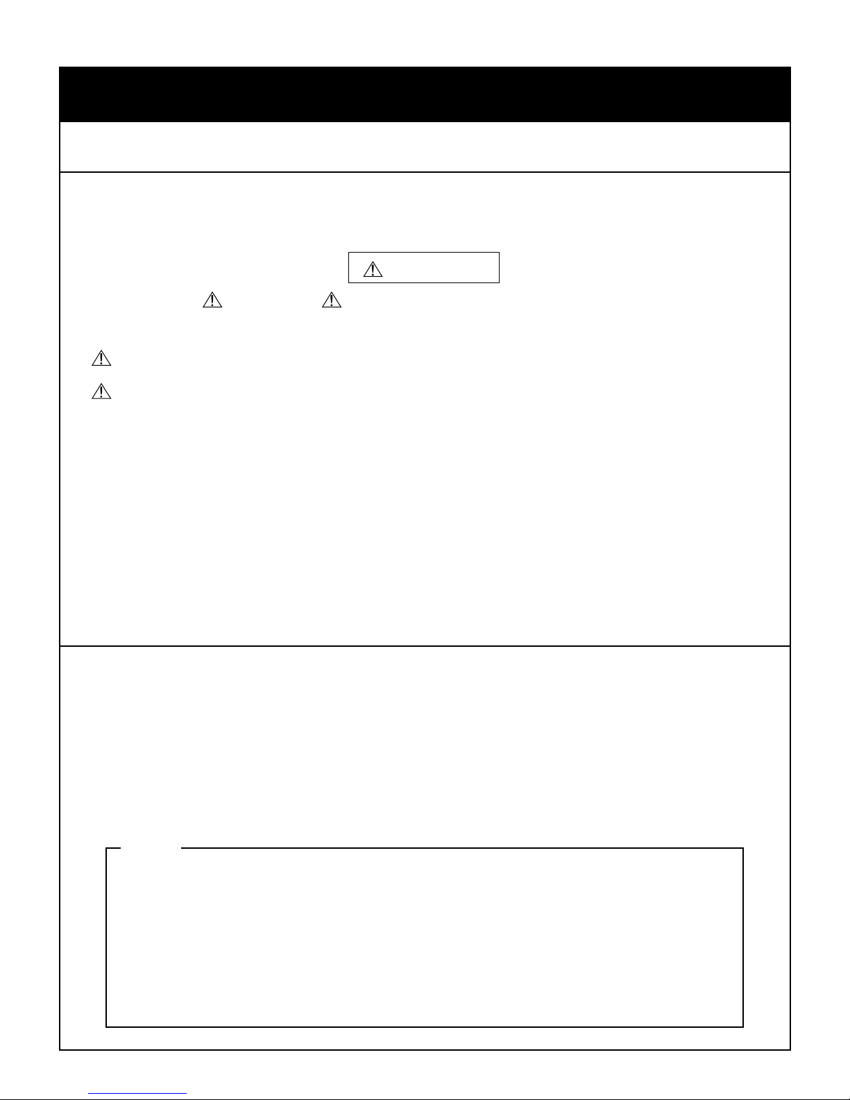
WARNING
•
There are several WARNING and CAUTION sections in this booklet concerning safely when installing or
removing the Mazda Mobile Start. Always read and follow them in order to prevent injuries, accidents, and possible
damage to the vehicle.
WARNING: Indicates a situation in which serious injury or death could result if the warning is ignored.
CAUTION: Indicates a situation in which bodily injury or damage to the vehicle could result if the caution is ignored.
• For areas indicating the tightening torque in this instruction manual, tighten to the specified torque using a torque wrench. For
areas in which the tightening torque is indicated inside parentheses ( ), the tightening torque is indicated as a reference value,
however tightening using a torque wrench is not necessary.
• Do not modify the Mazda Mobile Start.
• Do not install the Mazda Mobile Start in any way other than described in the following instructions.
• If in any doubt, please ask your Mazda dealer to install the accessory in order to prevent errors in installation.
• If you have any questions about the use of the accessory, ask your Mazda dealer for proper advice before using it.
• Mazda and its suppliers are not responsible for injuries, accidents, and damage to persons and property that arise from the
failure of the dealer or installer to follow these instructions.
• To ensure safety and reliability of the work, installation, removal and disposal work must carried out by an Authorized Mazda
Dealership.
• Be careful not to lose removed parts, and be sure that they are kept free from scratches, grease or other dirt.
PART NUMBER :
NOTE
To the dealer
Pleaseturnovertheseinstructionstothecustomerafterinstallation.
•
To the customer
Keeptheseinstructionsafterinstallation.Theinstructionsmaybenecessaryfor
•
installingotheroptionalpartsorremovalofthisaccessory.
Shouldthevehicleorthisaccessoryberesold,alwaysleavetheseinstructions
•
withitforthenextowner.
PART NAME :
VEHICLE :
Mazda Mobile Start (MMS)
Mazda CX-3 / Mazda2
0000-8F-Z80 (MMS ECU Kit)
0000-8F-P07 (MMS Harness Kit)
[KD53-V7-629 (Hood Switch)]
1
090003-33280700
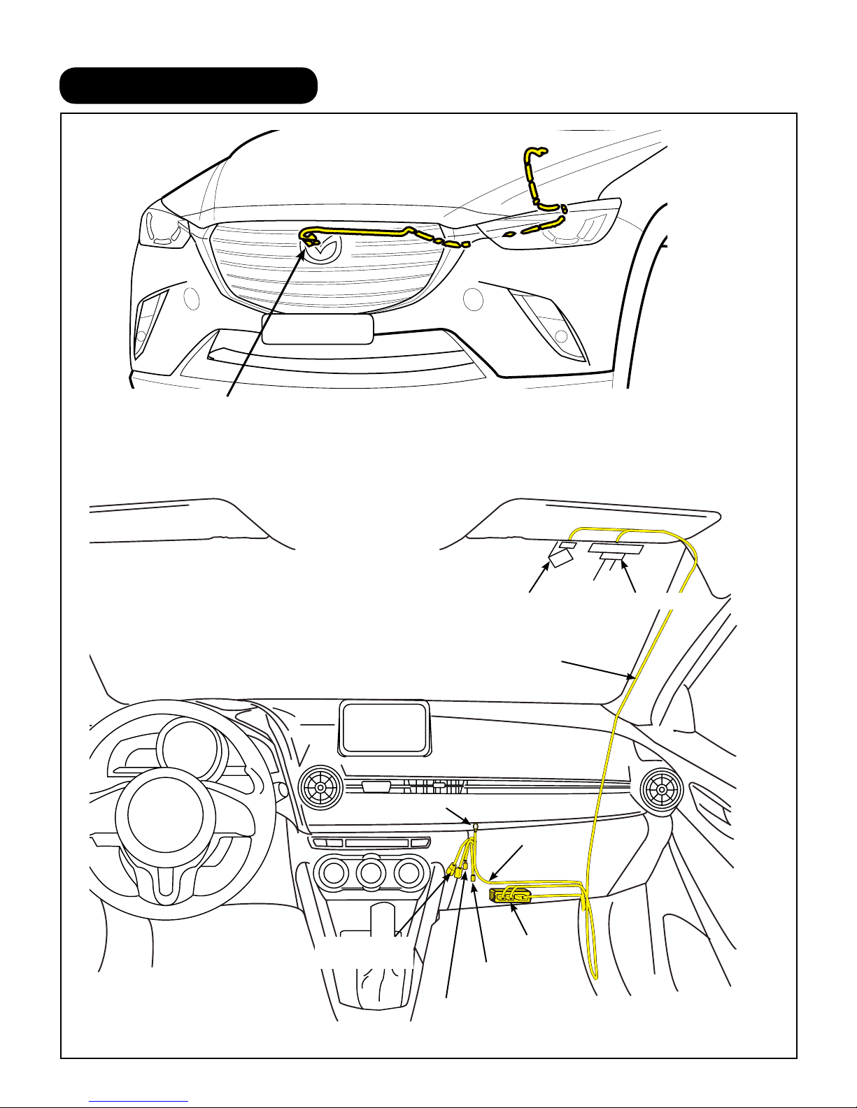
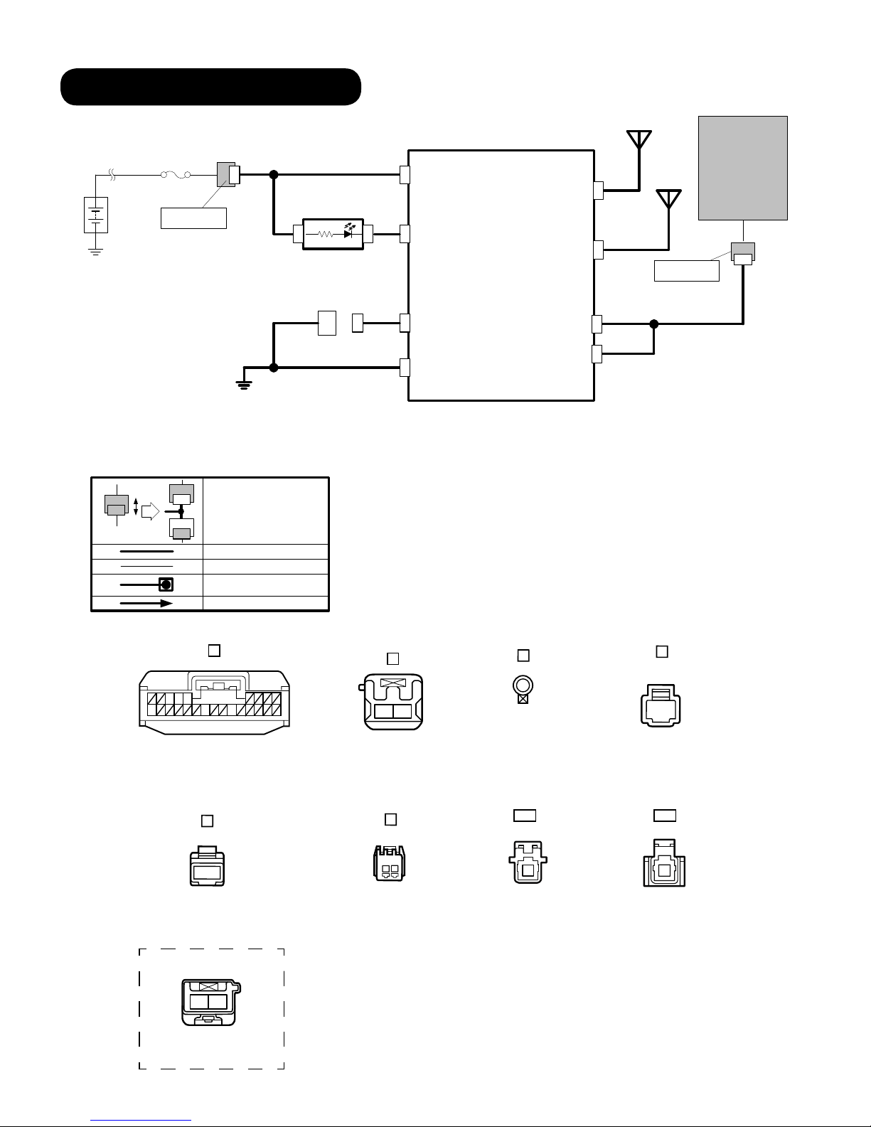
1. INSTALLATION VIEW
(Sold separately) Hood switch
(Only for vehicles without theft-deterrent or without i-ELOOP system)
GPS & TEL Antenna Cables
Harness (GND)
RES Diagnostic
Connectors
Connector
LED
Connector
GPS Antenna
MMS Harness
MMS ECU
MMS 2P
TEL Antenna
2
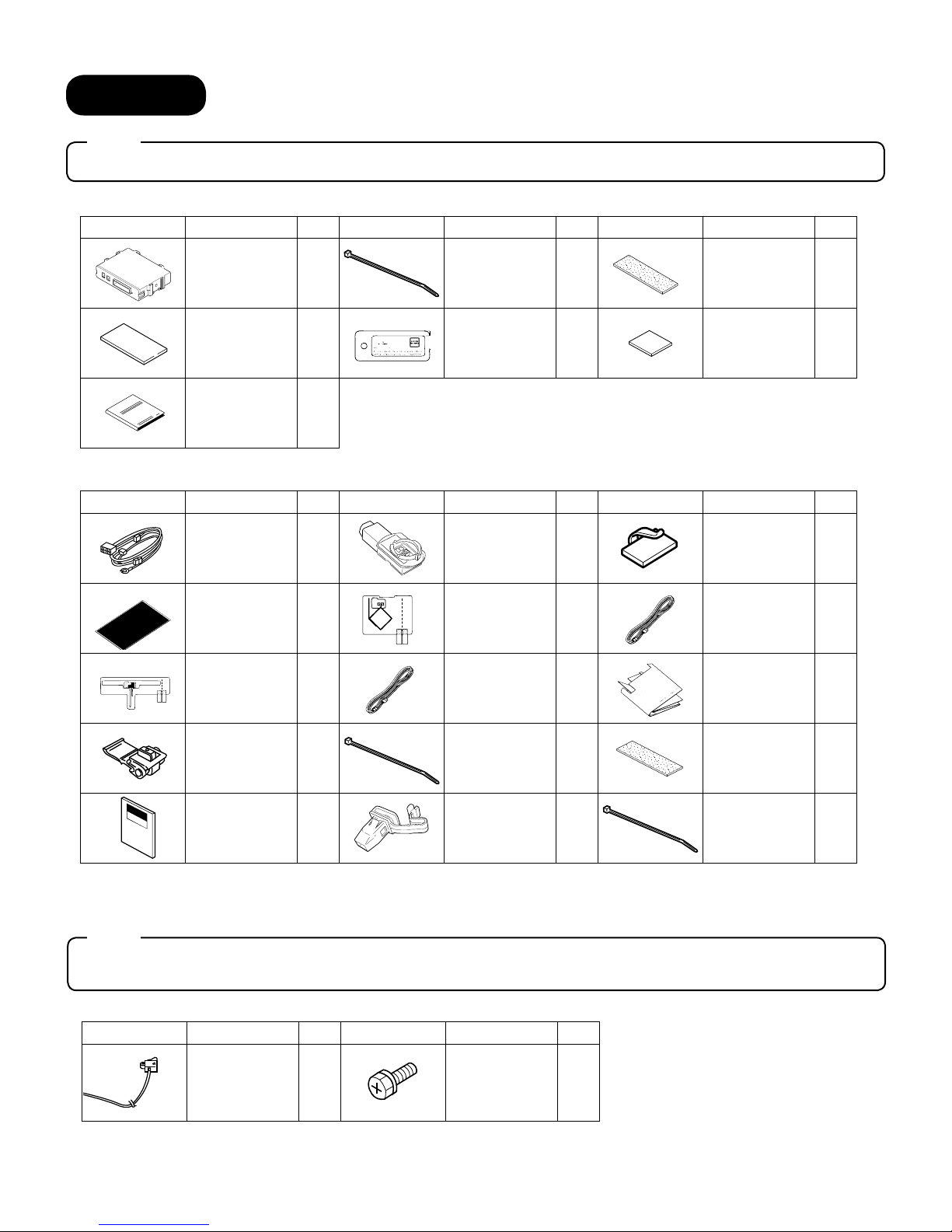
2. PARTS
Note
• Verify that the kit includes all the following parts and that they are free of dirt, scratches, or damage.
MMS ECU KIT (Part no. 0000-8F-Z80)
Part Part Name Qty. Part Part Name Qty. Part Part Name Qty.
MMS ECU
Double-sided
adhesive tape
(25 x 69mm)
Owner's Manual
1
1
1
Wire Tie
(White 200mm)
MMS Key Tag
5
1
Urethane
Foam tape
(35 x 115mm)
Double-sided
adhesive tape
(25 x 25mm)
HARNESS KIT (Part no. 0000-8F-P07)
Part Part Name Qty. Part Part Name Qty. Part Part Name Qty.
MMS Harness
FH Protection
Sheet
TEL Film
Antenna
1
1
1
LED
GPS Film
Antenna
TEL Antenna
Cable
1
1
1
«
Harness Clamp
GPS Antenna
Cable
Antenna
Template
2
3
2
1
1
«
Electro tap
Installation
Instructions
(ENG/SPA/FRE)
: Parts marked with a star mark are only used on vehicles without theft-deterrent or without i-ELOOP system.
«
1
3
Wire Tie
(White 200mm)
A-Pillar Clip
(D09W-68162)
15
1
Urethane
Foam tape
(35 x 115mm)
«
Wire Tie
(Black 200mm)
(Sold separately) The following parts are also necessary for installation.
Note
• These parts are not necessary for vehicles with theft-deterrent or with i-ELOOP system because the hood
switch is already equipped.
HOOD SWITCH KIT (Part no. KD53-V7-629)
Part Part Name Qty. Part Part Name Qty.
Hood switch
1
Screw
1
4
10
3
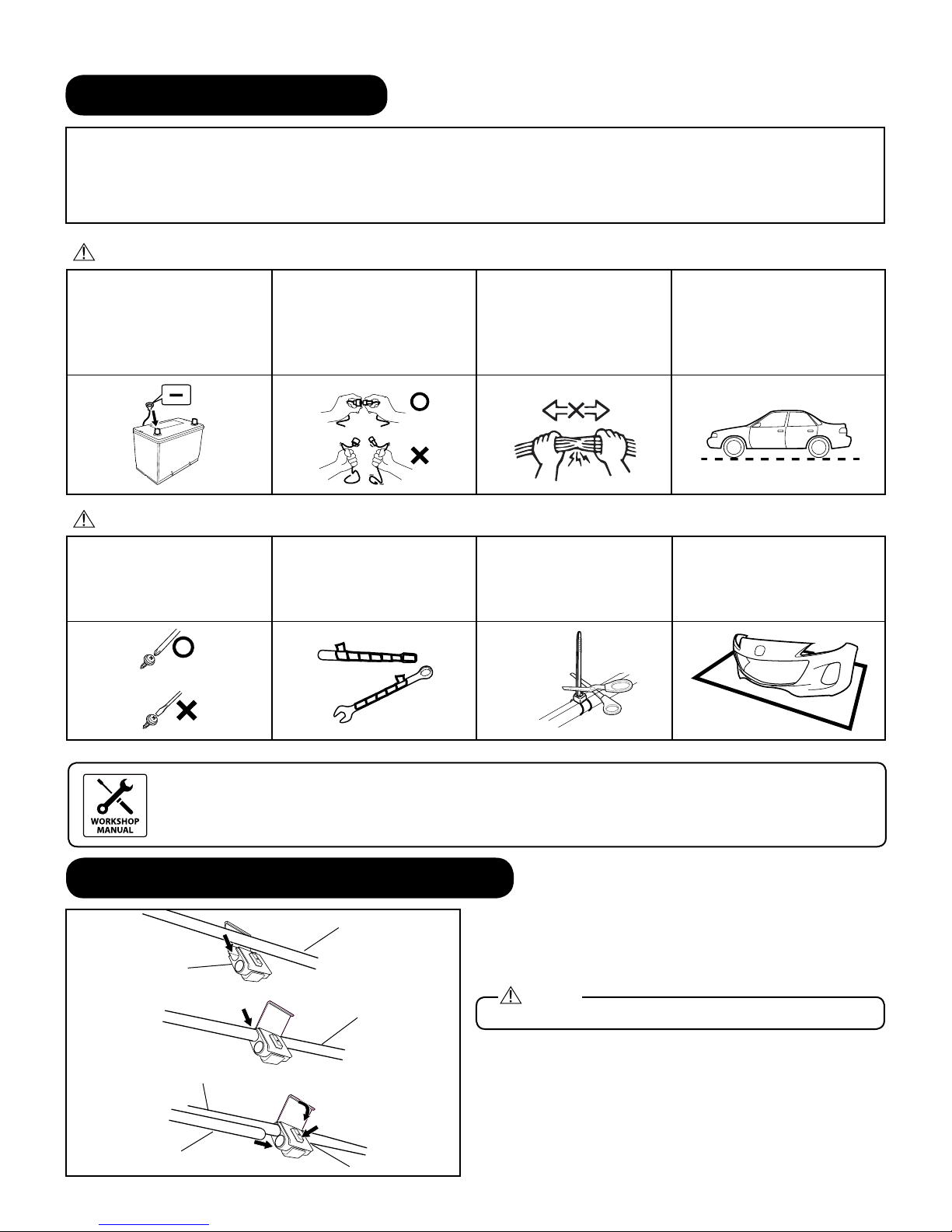
3. BEFORE INSTALLATION
WORKSHOP
MANUAL
REQUIRED TOOLS
• 10mm Socket Wrench • Scissors • Torque Wrench • Taped Flathead Screwdriver • Mat
• Electrical Tape • Panel Removal Tool • Soft clean cloth • Squeegee • Glass Cleaner • Nipper
• Pliers • Primer (3M Promoter-4298) • IPA (Isopropyl alcohol) • Phillips Screwdriver
WARNING
When the negative battery cable
is connected during operation, it
may cause electric shock or other
personal injuries. Disconnect the
negative battery cable before
removal/installation.
When connecting or disconnecting
connectors, grasp the connectors,
not the wires. Otherwise a short,
an accident from poor contact or
re may occur.
Do not pull the harness with
excessive force. Doing so can
cause a breakage or a shortrelated accident, as well as an
electrical short or re.
Park the vehicle on a level ground.
Set the vehicle on park (P) and
apply the parking brake. Be sure to
turn the ignition switch off, otherwise
the vehicle can move, causing
personal injury or vehicle damage.
CAUTION
Using improper tools may cause
damage and or broken parts.
Use the correct tool for the job.
Wrap protective tape around
screwdrivers and fastener
removal tools to prevent
scratching the vehicle.
Put the removed parts and the
parts in the kit on the protective
sheet to prevent scratches.
Excessive length of wire tie may
interfere with other parts and
cause damage. Cut unnecessary
part up to about 5 mm {0.19 in}
from the xed point.
• When the negative battery cable is removed, the clock, radio, trim meters and other memories will be
erased. Make sure to record the content of the memory.
• Refer to the Workshop Manual for removal and installation of vehicle parts. Not following the procedures for
removal/installation in the Workshop Manual could result in an accident or vehicle malfunction.
4. CONNECTION USING ELECTRO-TAP
Vehicle wiring harness
1
Electro tap
2
Vehicle wiring harness
Harness
3
Vehicle wiring harness
5
4
Lock
Firmly press using pliers
Terminal
Branch connection procedure using electro tap.
1. Insert the vehicle wiring harness into the electro tap.
2. Fold the electro tap as shown in the figure and lock it.
Caution
• Firmly engage the lock part until a click sound is heard.
3. Insert the harness to the end of the electro tap.
4. Firmly press the electro tap terminal using pliers.
5. Fold the electro tap in the direction of the arrow shown in
the gure and lock it.
4
5. CONNECTION DIAGRAM
GPS
20XX-
CONNECTORS
MAZDA MOBILE START (MMS)MMSMAZDA
ANTENNA
Battery
VEHICLE
CONNECTOR
ROOM
Pin : 1
Pre connector
GND (M6)
C1
**
Connector to Connector
**
MMS Wire
Vehicle Wire
Scotch lock connection
MMS or Vehicle Terminal Insert
A
SSU
(Start
/
B1
+B
A10
GPS
GPS
TEL
ANTENNA
Stop
control Unit)
RES LED
F2
F1
LED
A5
TEL
TEL
MMS ECU
Pre connector
Pin:2
B2
RES Connector
E1
D1
RDIG
A16
GND
A19
STX
SRX
A4
A3
B
C
D
5
34
10
16 19
(FEMALE PIN)
E
1
(FEMALE PIN)
VEHICLE OPTION CONNECTOR
112
(
)
MALE PIN
21
(
FEMALE PIN
F
(MALE PIN)
(TERMINAL PIN)
)
TEL
1
(
FEMALE PIN
)
1
(MALE PIN)
GPS
1
(
FEMALE PIN
)
5
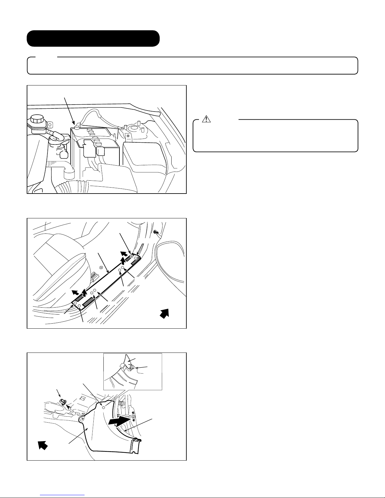
6. VEHICLE DISASSEMBLY
Note
• Be careful not to damage or lose any parts removed from the vehicle since they will be reused.
1. Place the vehicle in park with the parking brake set.
Negative battery terminal
2. Disconnect negative battery terminal and wrap tape
around it to insulate.
Warning
• When the negative battery cable is connected during
operation, it may cause electric shock or personal
injuries. Disconnect the negative battery cable before
removal / installation.
Bolttighteningtorque:4.0-6.0N•m(2.9-4.4ft•lbf)
Tab B
Cap Nut
Cap Nut
(3)
Front Scuff Plate
(4)
Clip B
Hook B
Clip
Clip
Pin B
Tab A
(2)
(1)
Clip A
Hook A
Pin A
Vehicle Front
Front Side Trim
Front Side Trim
(Backside)
(Backside)
Clip
Clip
Passenger side scuff plate removal
1. Use shaded area to pull (1) and lift (2) Passenger side
Front Scuff Plate to detach Tab A and Clip A.
2. Use shaded area to pull (3) and lift (4) Passenger side
Front Scuff Plate to detach Tab B and Clip B.
Passenger side front trim removal
1. Peel back the Seaming Welt.
2. Remove Cap Nut.
3. Remove Front Side trim.
Front Side Trim
Front Side Trim
Vehicle Front
Vehicle front
Weather strip
Seaming Welt
6
Vehicle front
Hook B
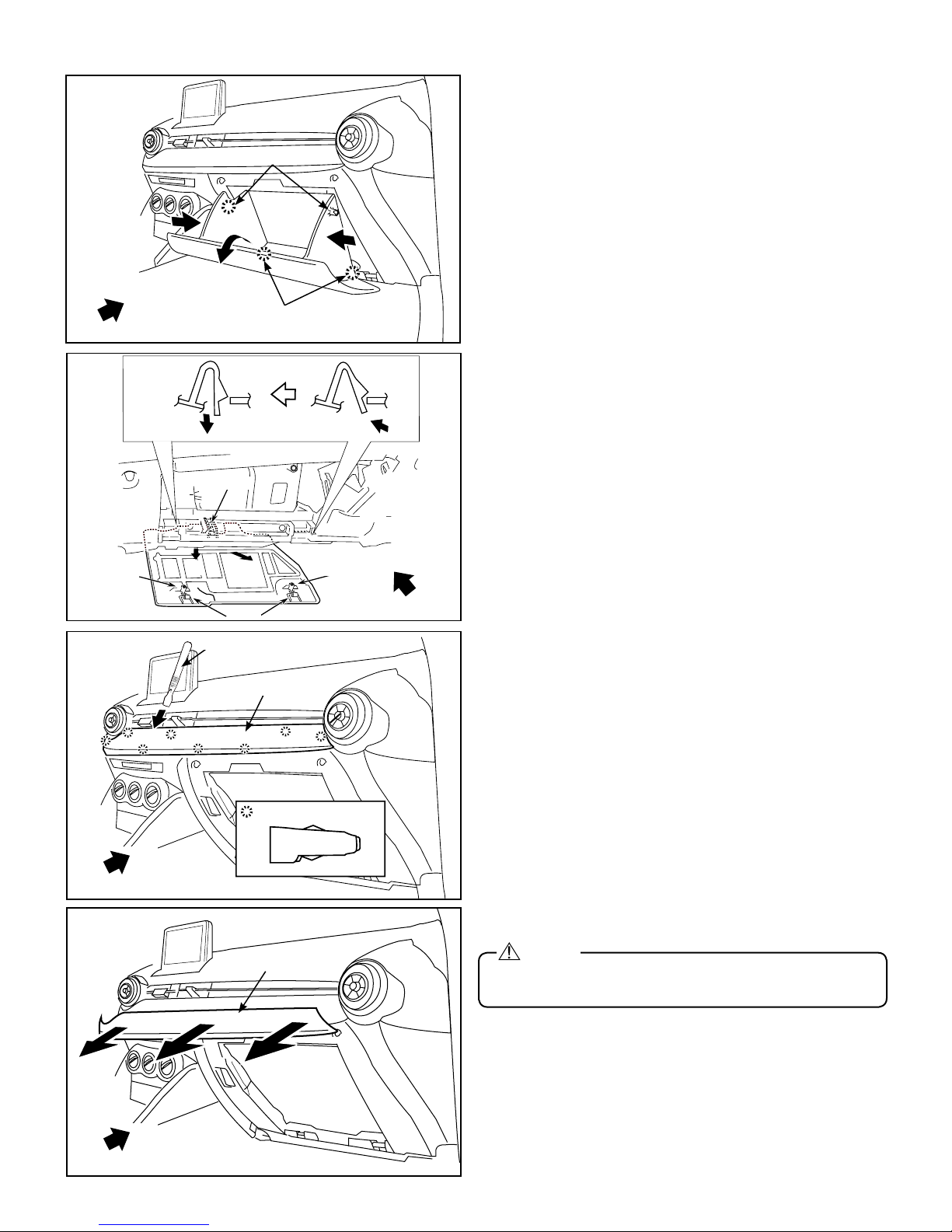
Glove box removal
1. Push both sides of the Glove box then pull to dislodge 2
Hooks (B).
2. Remove the Glove box by pulling to dislodge 2 bottom
Hooks (C).
Vehicle Front
Pin B
Hook A
(2)
(2)
Removal tool
Guide C
(3)
Hook A
Decoration panel
Hook C
3. Remove Glove box under cover in order of arrows (1-3).
(1)
Pin B
Vehicle Front
Decoration panel removal
1. Place hand into the glove compartment opening and push
out 3 clips (A) towards the rear of the vehicle.
2. Disengage the remaining clips (A) using the Removal tool.
Clip A
Vehicle Front
Vehicle front
Decoration panel
Vehicle Front
3. Remove the decoration panel.
Caution
• If decoration panel is pulled out on one side, you will damage
it, make sure to pull the whole panel straight out.
7
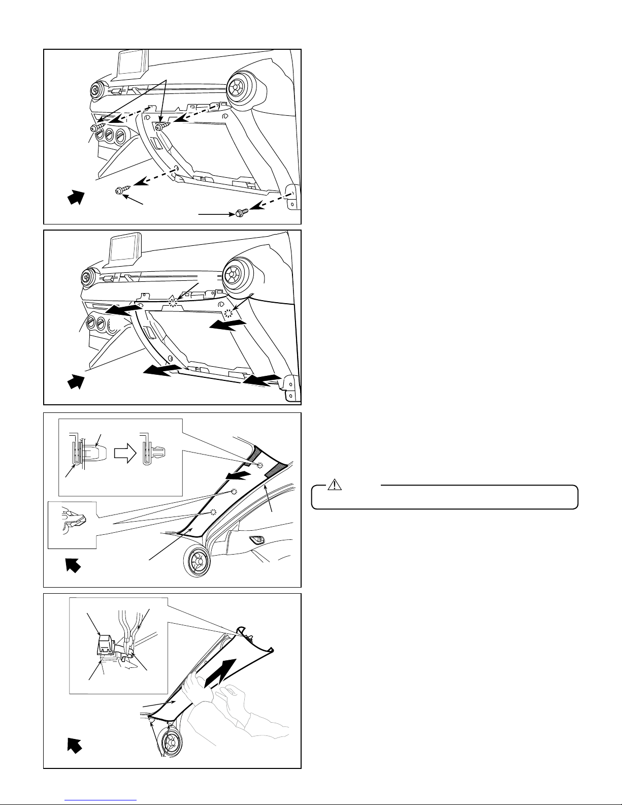
Vehicle front
A-pillar trim
Guides
Grommet
Nipper
Lead Wire
Clip B
Vehicle Front
(3)
Screw
Screws
Bolt
Clips
Clip
(2)
Clips
Clip
Passenger side lower panel removal
1. Remove 3 Screws and 1 Bolt.
Bolttighteningtorque:2.0-6.0N•m(1.5-4.4ft•lbf)
2. Remove lower panel by pulling in the order of arrows (1-4).
Vehicle front
Vehicle Front
Clip B
Clip B
Clip A
Clip A
Vehicle Front
Grommet
Part B
Clip B
Clip B
Passenger Side A-Pillar
Nipper
Tab
(4)
(1)
A-Pillar trim removal
1. Partially peel back the seaming welt.
2. Dislodge the Passenger side A-pillar trim by pulling on the
(1)
shaded area to disengage Clip B and A.
Caution
• Do not use excessive force, A-pillar could be damaged.
Seaming Welt
Seaming Welt
3. Cut the A-pillar tab connecting part B and the grommet of
the A-pillar tether clip.
4. Remove the A-pillar trim while detaching guides.
Vehicle Front
Vehicle front
Vehicle front
A-Pillar Trim
Guides
8
 Loading...