

Mazda 0000-8F-N02B Instructions Manual
GENUINE ACCESSORIES
®
INSTALLATION INSTRUCTIONS
PART NUMBER (s):
0000-8F-N02B
REMOTE START SYSTEM
APPLICABLE MODELS:
2007 > MAZDA CX-9
ALL MODELS
NOTE: BOTH VEHICLE IGNITION KEYS ARE REQUIRED AT TIME OF
INSTALLATION. DO NOT BEGIN INSTALLATION WITHOUT BOTH
KEYS.
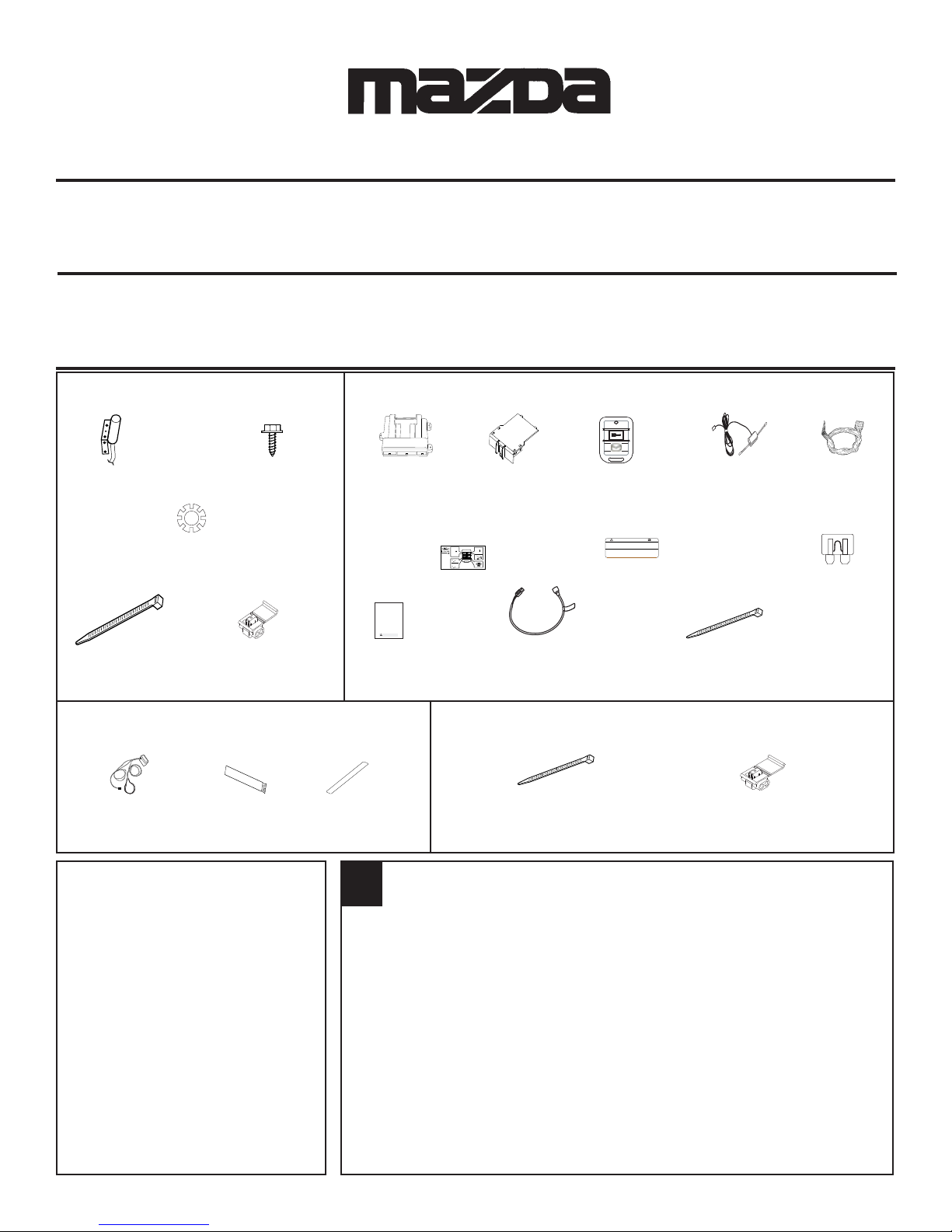
HOOD SAFETY SWITCH KIT CONTENTS
P/N: 0000-8F-H03
Hood Safety
Switch
(QTY 1)
Locking
Washer
(QTY 2)
Wire Tie
(QTY 2)
1/4” Self
Drilling Screws
(QTY 2)
IDC Wire Tap
(QTY 2)
Remote Start DNA Card Remote Start Dipole Antenna Remote Start
Control Module (QTY-1) Transmitters (QTY-1) Wire Harness
(QTY-1) (QTY-2) (QTY-1)
P/N: 0000-8F-Z01 P/N: 0000-8F-M21 P/N: 0000-8F-Z02 P/N: 0000-8F-Z10 P/N: 0000-8F-N18A
2 sec.
5X
2 sec.
30
sec.
Wallet
Card
MAZDA
GENUINE ACCESSORIES
Vehicle Remote Start System
Owner's Manual
Featuring PowerCode Technology
TM
For the Ultimate in Comfort, Convenience and Security
(QTY 1)
TM
Owners
Manual
(QTY 1)
P/N: 0000-8F-Z03
KIT CONTENTS
Programming
Button
(QTY 1)
WARNING: / AVERTISSEMENT
This vehicle is equipped with a remote controlled engine starter.
To reduce the risk of serious Injury or death, switch engine starter
system into service mode and disconnect the vehicle battery
before performing any service on the vehicle.
Ce véhicule est doté d'un démarreur à distance. Pour réduire les
risques de blessures graves ou mortelles, mettre le démarreur à
distance en mode service et débrancher la batterie du véhicule
avant d'effectuer des travaux d'entretien sur celui-ci.
Underhood
Sticker
(QTY 1)
P/N: 0000-8F-Z12
Mini Fuses
(QTY - (1) 5 AMP)
(QTY - (7) 15 AMP)
Long Wire
Tie
(QTY 4)
IMMOBILIZER INTERFACE KIT CONTENTS
P/N: 0000-8F-H05A
Immobilizer Interface Adhesive Primer 2- Sided Tape
Module and Harness (QTY-1) (QTY-1)
(QTY-1)
TOOLS REQUIRED
0
SAFETY GLASSES
ELECTRICAL TAPE
WIRE CUTTERS
PLIERS
ALCOHOL or GLASS CLEANER
#2 PHILLIPS SCREWDRIVER
POWER DRILL
9/32” DRILL BIT
FIBER STICK
10 mm SOCKET AND RATCHET
1. CLEAN HANDS
2. OPEN DRIVER’S DOOR WINDOW
3. RECORD RADIO STATION PRESETS
4. SET PARKING BRAKE
5. ENSURE VEHICLE WILL START UTILIZING THE IGNITION KNOB & VALET
KEY (SMART-KEY EQUIPPED VEHICLES ONLY)
6. DISCONNECT AND ISOLATE NEGATIVE BATTERY TERMINAL
7. VEHICLE MUST BE AT ROOM TEMPERATURE
1/4” SOCKET AND DRIVE
3/8” DRIVE TORQUE WRENCH
3/8” DRIVE 10mm SOCKET
HI-TEMPERATURE SILICONE
PARTS BAG CONTENTS
Wire Tie
IDC Wire Tap
(QTY-10)
(QTY-8)
VEHICLE PREPARATION
1
4280159 Rev. A 10/10
0
(
)
)
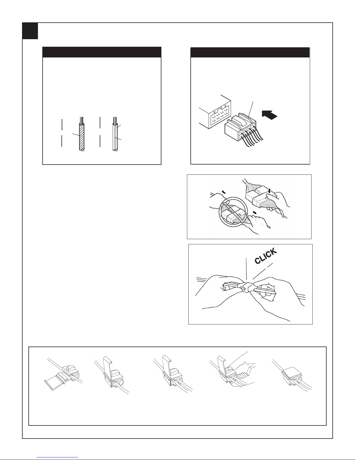
ELECTRICAL SYSTEM GENERAL PROCEDURES
W
ire c
olo
r code
Two-color wires are indicated by a two-letter
symbol.The first indicates the base color of the
wire, the second the color of the stripe.
For example:
W/R is a white wire with a red strip
BR/Y is a brown wire with a yellow strip
Symbol
(Example)
Solid color wire Striped wire
C
onn
Connector diagrams show connectors on the harness
side. The terminal indicates the view from the harness
side.
(Example)
ecto
r diagrams
Connector on harness side
White
Black
B
D
isconnect
When disconnecting connector, grasp the connectors,
not the wires.
L
ocking
When locking connectors, listen for a click indicating
they are securely locked.
ing
C
onnector
W/R
C
onnector
base color
Red(stripe
s
Unused terminals are indicated by ∗ .
N
O GOO
NO GOOD
D
View from harness side
IDC Wire Tap Procedure
Place IDC on vehicle
Close side of IDC.
wire.
Insert remote start
wire into IDC.
2
Crimp IDC metal tab
over both wires until
flush with top of IDC.
4280159 Rev. A 10/10
Close top of IDC.
0
ELECTRICAL SYSTEM GENERAL PROCEDURES; continued
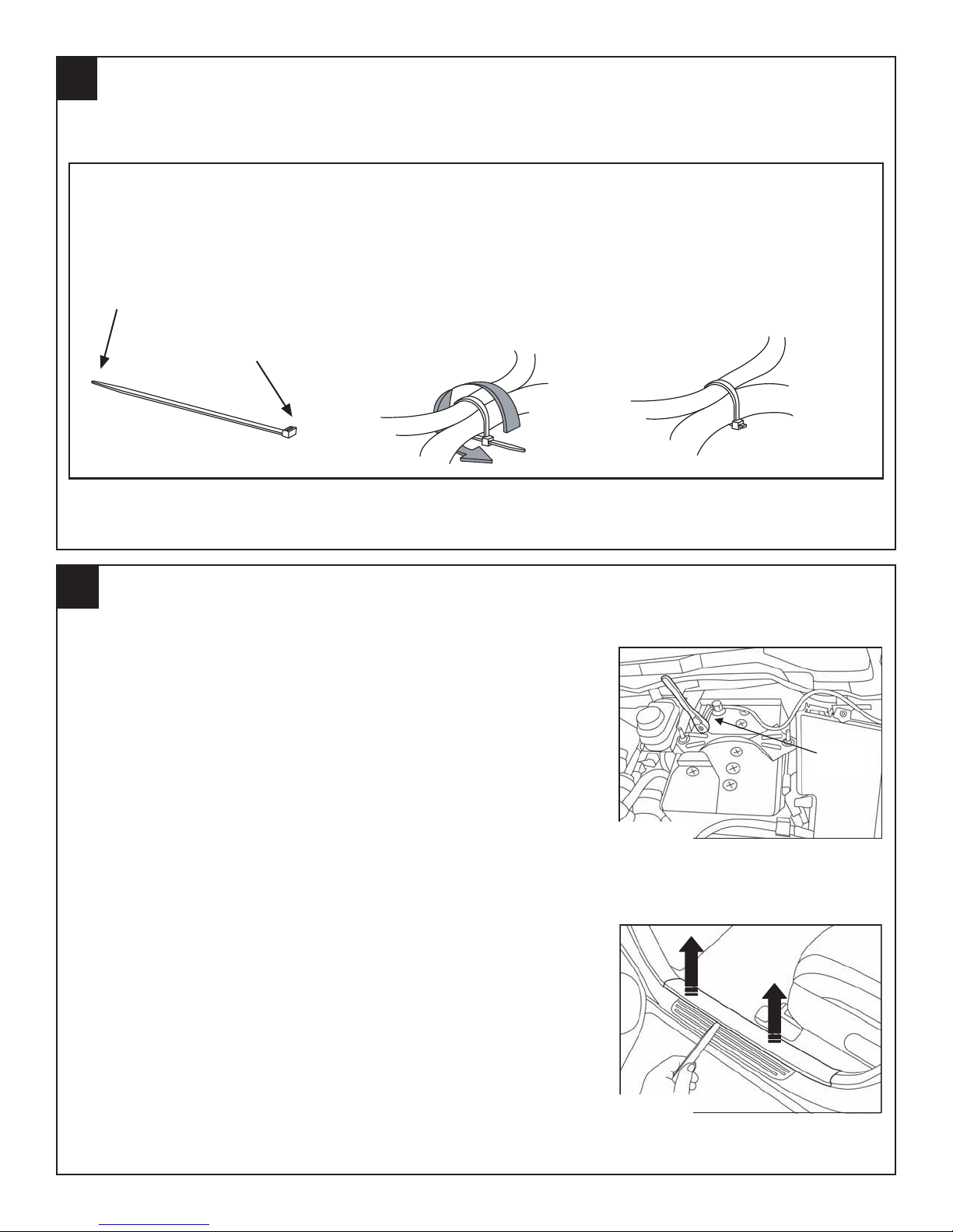
Wire Tie Procedure
Tapered End
1
VEHICLE PREPARATION
1.Wrap wire tie around
the harnesses you
wish to secure
together.
Wire Tie Head
2.Insert the Tapered
End of the wire tie
into the Wire Tie
Head.
3.Pull the Tapered End
through the Wire Tie Head
until the wire tie is snug.
4.Trim wire tie end
after tightening.
1. Disconnect and Remove Battery
a. Disconnect and isolate the negative and positive battery
terminals. (FIGURE A)
b. Remove battery hold-down bracket assembly by loosen-
ing both 10 mm nuts and pivoting lower retainers toward
vehicle dashwall. (FIGURE A)
c. Carefully remove the battery from vehicle.
2. Remove the following components:
a. Using a fiber stick, remove the driver’s side scuff plate.
The scuff plate is held by 3 clips. (FIGURE B)
10 mm
Socket
FIGURE A
FIGURE B
3
4280159 Rev. A 10/10
1
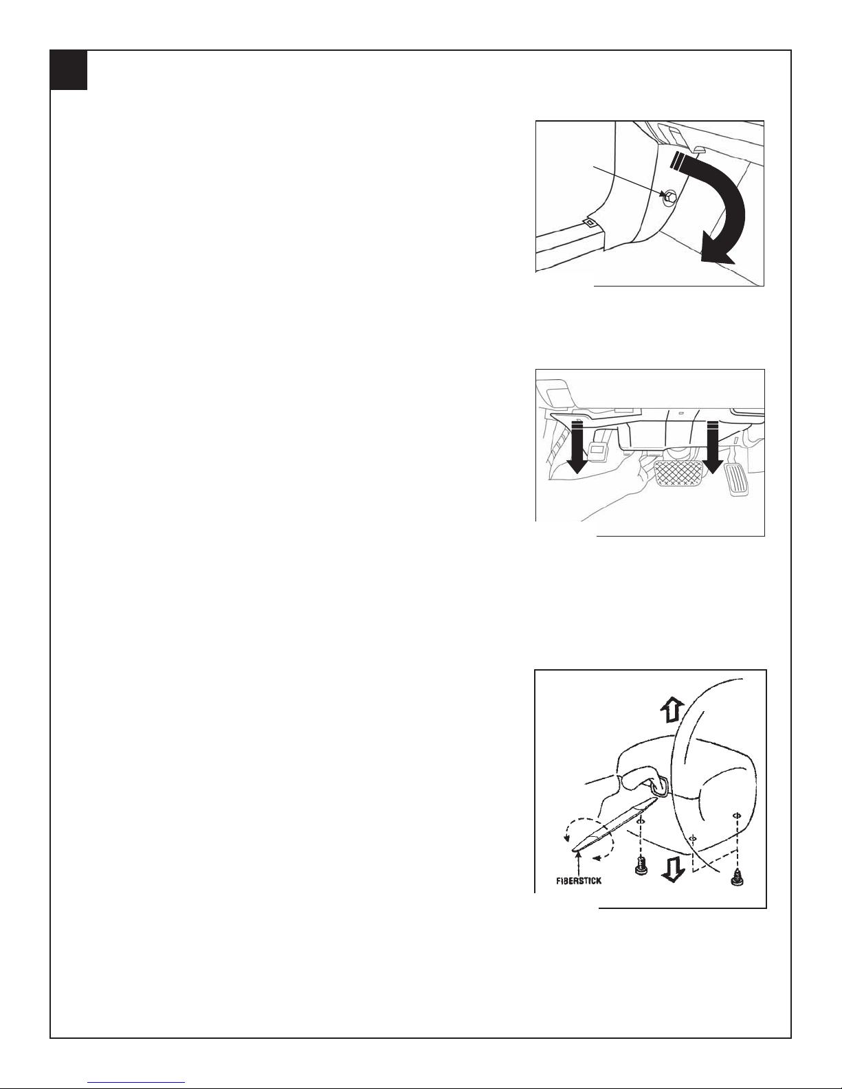
VEHICLE PREPARATION; continued
b. Remove the driver’s side kick panel by removing the plas-
tic nut. (FIGURE C) Partially peel back the rubber
weatherstrip away from the kick panel. Insert a fiber stick
between the body and kick panel to disengage the retaining clip. Gently pull the kick panel toward the
passenger’s side of the vehicle to remove.
c. Remove the black, lower dash panel by using a fiber stick
to pull the plastic center button of both plastic fasteners
out to disengage. Use a fiber stick to disengage the single
clip located at the front, center of the panel and remove.
(FIGURE D)
Plastic Nut
Plastic Nut
Fig. 1-4
FIGURE C
d. Smart-Key equipped vehicles only - Remove the ignition
knob by depressing both buttons on either side of knob
and pulling away from ignition switch.
e. Remove the three (3) phillips head screws from the lower
steering column cover. (FIGURE E)
f. Insert a fiber stick between the combination switch and
the lower cover. Gently rotate the fiber stick until top and
bottom covers separate. (FIGURE E)
g. Retractable Key equipped vehicles only - Gently unclip
the ignition key light and remove the lower cover.
FIGURE D
FIGURE E
4
4280159 Rev. A 10/10
REMOTE START CONTROL MODULE PREPARATION
2
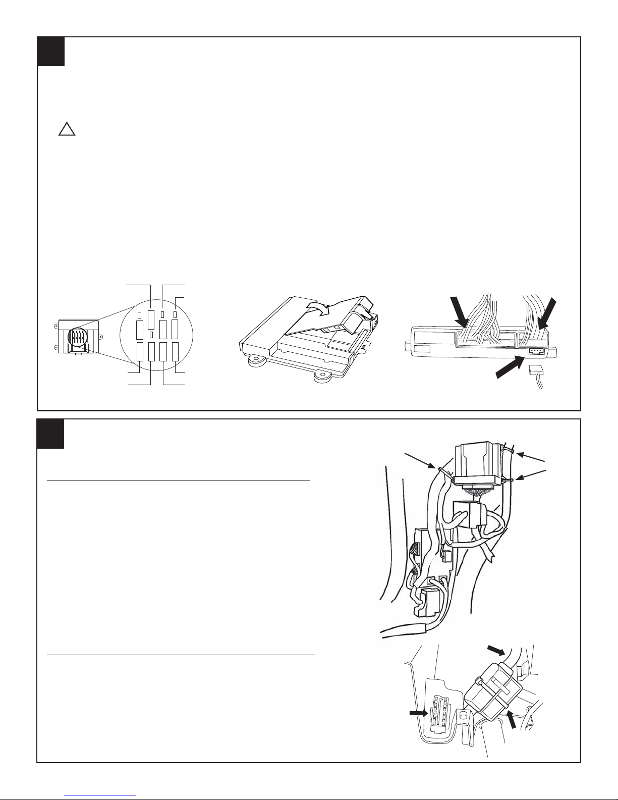
1. Insert the supplied fuses into the remote start control module as shown below. (FIGURE F)
The fuses fit tightly, so use the flat tip of a fiber stick to push them in place, if necessary.
2. Install DNA card into the remote start control module as shown below. (FIGURE G)
CAUTION: Use care to assure that both rows of the multi-pin connector are aligned and
!
seated properly or the remote start system will NOT operate properly.
3. Plug the supplied wire harness 10-pin and 24-pin connectors into the remote start control module. (FIGURE H) Make sure the connectors are seated completely. NOTE: The connectors will
only plug into the remote start control module one way.
4. Plug the supplied immobilizer interface 4-pin connector into the remote start control module.
(FIGURE H)
NOTE: TAPE OFF THE WHITE WIRE (IF EQUIPPED) COMING FROM THE 4-WAY
CONNECTOR (THIS WIRE IS NOT USED ON THIS SYSTEM).
DOME LIGHT
TRUNK RELEASE
15
15
15
15
5
15
15
15
15
15
15
-+
15
15
15
PK LIGHTS
DOOR LOCKS
15
-+
5
24-pin
Remote Start
Wire Harness
10-pin
HVAC 1
FIGURE F
REMOTE ENGINE START MODULE AND IMMOBILIZER INTERFACE MOUNTING
3
HVAC 2
MAIN B+
IGNITION
FIGURE G
Wire Tie
FIGURE H
Tie Wraps
REMOTE ENGINE START MODULE MOUNTING
1. Locate the two large wire harnesses high up under the
dashboard running near the vehicle dashwall.
2. Using (3) supplied, long wire ties, secure the remote start
control module to the wire harnesses. (FIGURE I)
NOTE:EXTREME CARE MUST BE TAKEN TO ROUTE
THE REMOTE START WIRING HARNESS AWAY
FROM ANY EXISTING INSTALLED
ACCESSORIES.
IMMOBILIZER INTERFACE MODULE MOUNTING
1. Locate the large wire harness routed between the steering column and diagnostic connector. (FIGURE J)
FIGURE I
4-pin
Immobilizer
Wire Harness
Wire Tie
Wire
Harness
2. Using (1) supplied, long wire tie, secure the immobilizer
interface to the wire harness. (FIGURE J)
Diagnostic
Connector
Wire
FIGURE J
5
4280159 Rev. A 10/10
Tie
4
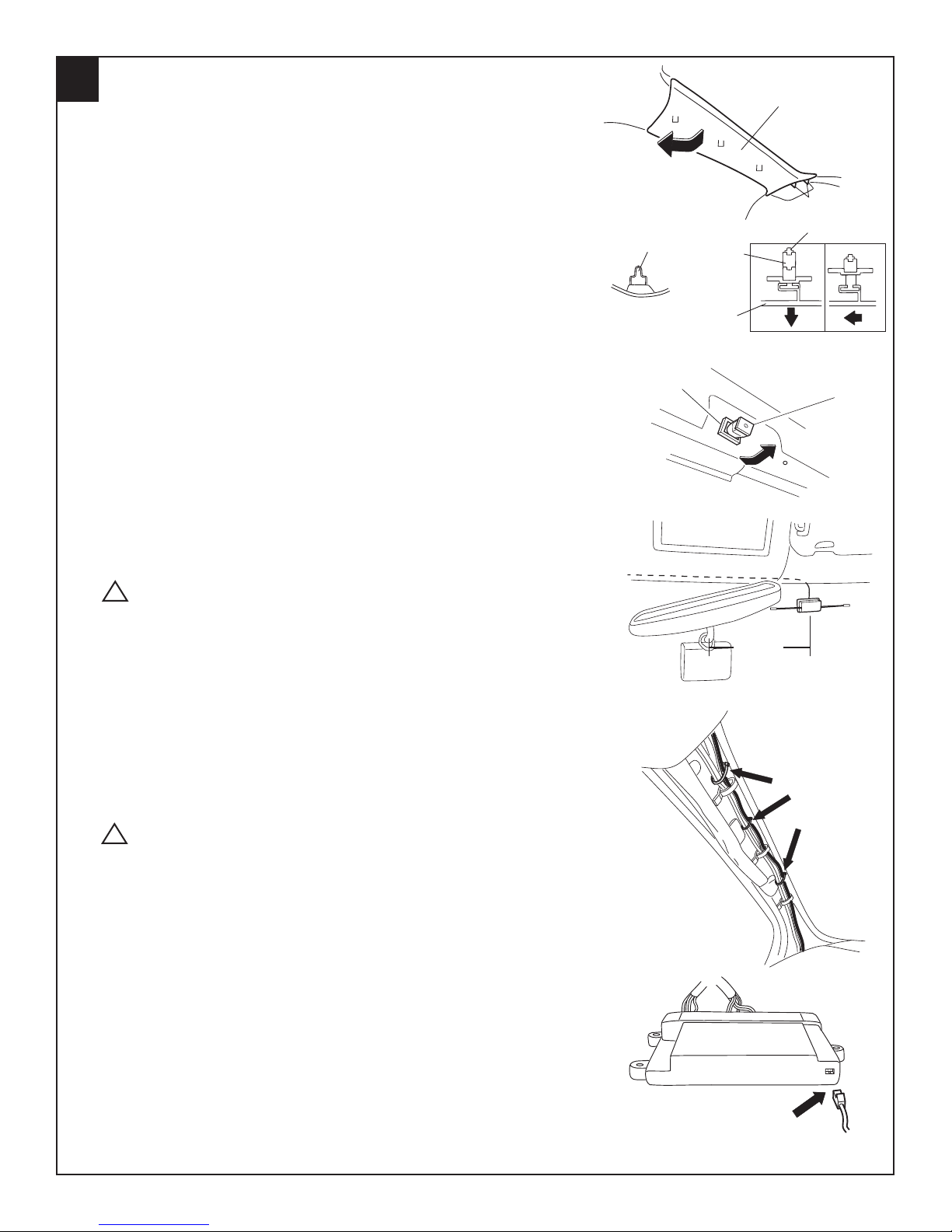
DIPOLE ANTENNA MOUNTING
1. Driver’s A-Pillar Trim Removal/Installation
a. Partially peel back the rubber weatherstrip away from the
A-pillar trim.
b. Pull the A-pillar trim, then disengage clips A. (FIGURE K)
c. Pull the A-pillar trim, then disengage clip B (Picture 1).
d. Pull the A-pillar trim upward, then disengage clip B from
the A-pillar trim (Picture 2).
e. Disengage the tabs from the dashboard, then remove the
A-pillar trim.
f. Pull clip B out, then rotate 45 degrees. (FIGURE L)
g. Remove clip B from the grommet by pulling it outward and
replace clip B into A-pillar trim for reassembly.
2. Clean mounting spot with an alcohol pad prior to mounting.
Mount the dipole antenna to the windshield 220 mm to the
right of the center of the mirror base on the windshield, directly below the black windshield frit. (FIGURE M)
CAUTION: Mounting dipole antenna on black windshield
!
frit will result in reduced operating range.
CLIP A
FIGURE K
GROMMET
FIGURE L
B
A
GROMMET
A-PILLAR
UPPER TRIM
A-PILLAR
UPPER TRIM
A
45
TAB
CLIP B
(1)
(2)
CLIP B
3. Run the antenna wire above the headliner to the driver’s Apillar, using a fiber stick to secure under the headliner.
(FIGURE M)
4. Route the antenna wire down the A-pillar, securing it to the
existing wire harness with (3) supplied, short wire ties.
(FIGURE N)
CAUTION: Do not secure antenna wire to the moonroof
!
drain tube, if equipped, or to any airbag components.
5. Route the antenna wire behind the left side of the dashboard
and over to the remote start control module. Plug the 2-pin
antenna connector into the 2-pin port on the bottom of the remote start control module. (FIGURE O)
6. Re-install the driver’s side A-pillar panel and re-install the rubber weatherstrip along the A-pillar.
FIGURE M
FIGURE N
220 mm
220 mm
Wire
Ties
FIGURE O
6
4280159 Rev. A 10/10
2-pin
5
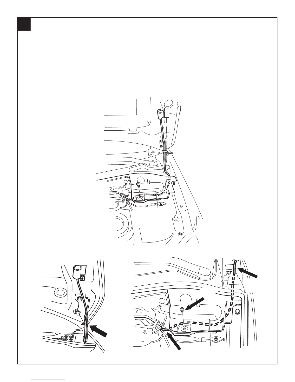
HOOD SAFETY SWITCH MOUNTING
1. Using (2) supplied, 1/4” self drilling screws and (2) supplied lock washers, secure the hood safety
switch to the drivers side of the vehicle’s hood 105 mm above the top of the hood mounting bracket
and 70 mm from the side edge of the hood. (FIGURE P & Q)
2. Route the hood safety switch wiring down into the engine compartment along the inside of the
hood hinge and secure using (1) supplied, short wire tie. (FIGURE Q)
3. Remove the plastic phillips screw in cowl panel to route the hood safety switch wiring underneath.
Gently lift the cowl panel and tuck hood safety switch wiring under the cowl panel and into the
engine compartment. Continue routing toward the main wire harness grommet in the vehicle
dashwall. (FIGURE P & R)
70 mm
105 mm
FIGURE Q
FIGURE P
Wire
Tie
FIGURE R
Hood Safety
Phillips
Screw
Hood Safety
Switch Wiring
7
4280159 Rev. A 10/10
Switch Wiring
5
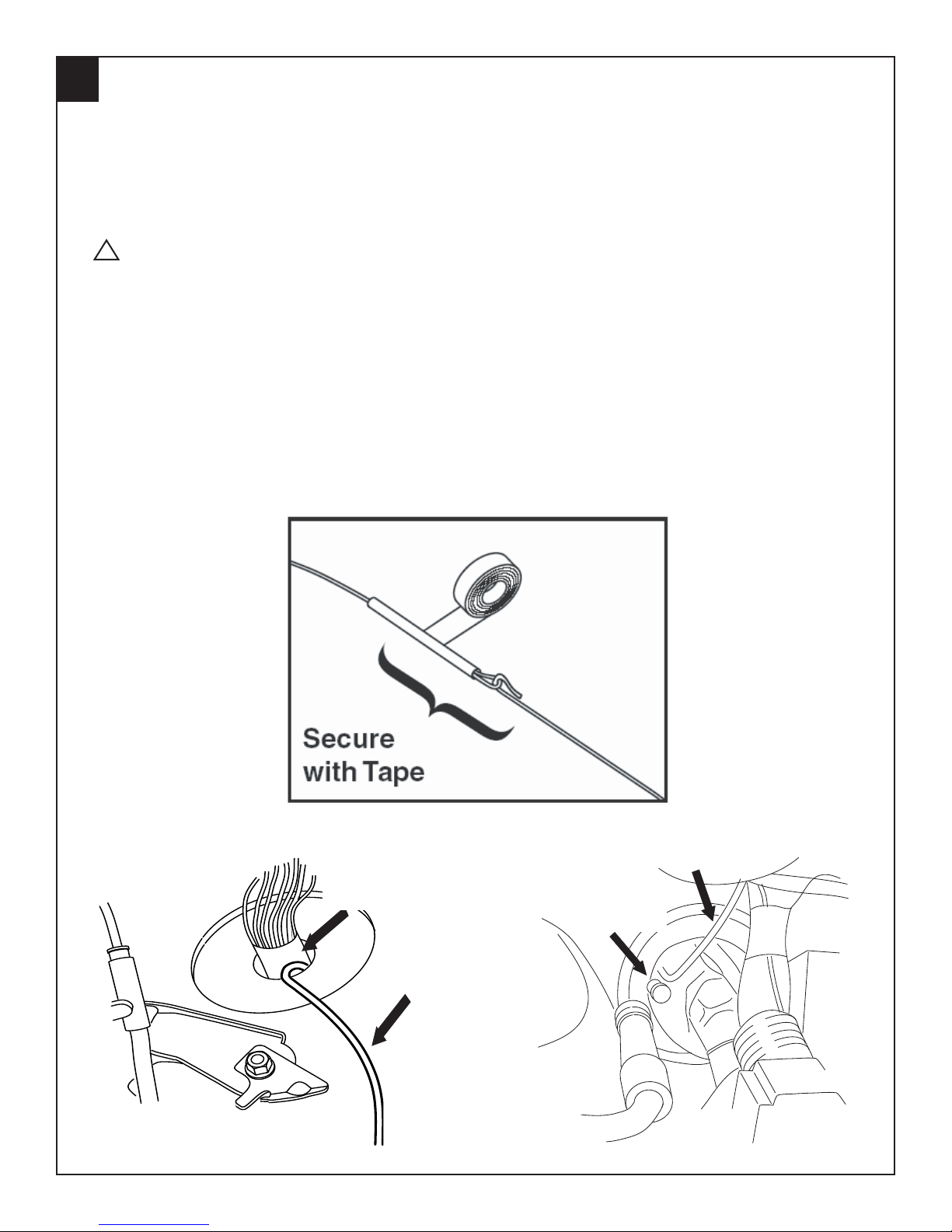
HOOD SAFETY SWITCH MOUNTING, continued
4. Using fish wire, pull the hood safety switch wiring and WHITE/BLACK tach wire from the remote start harness through the main wire harness grommet:
a. From inside of the vehicle, bend approximately three (3) inches of tach wire at wire end.
b. Using electrical tape, secure fish wire to tach wire as shown. (FIGURE S)
c. Insert the fish wire along with tach wire through the main wire harness grommet into the
engine compartment. (FIGURE T & U)
!
CAUTION: Do not pierce the main wire harness with fish wire when pulling through
main grommet.
d. Disconnect tach wire from fish wire and pull remaining slack of tach wire from the inside
of the vehicle out into the engine compartment.
e. Bend approximately three (3) inches of hood safety switch wiring at wire end.
f. Using electrical tape, secure fish wire to hood safety switch wiring as shown.
(FIGURE S)
g. Pull fish wire and hood safety switch wiring back through main wire harness grommet
into the vehicle. (FIGURE T & U)
h. Disconnect hood safety switch wiring from fish wire and pull remaining slack of hood
safety switch wiring from the engine compartment into the vehicle.
NOTE: Ensure the tach wire does not get pulled back into the vehicle.
FIGURE S
FIGURE T
Main Wire
Harness Grommet
Hood Safety
Switch Wiring
Hood Safety
Switch Wiring
Main Wire
Harness Grommet
FIGURE U
8
4280159 Rev. A 10/10
 Loading...