

Mazda 3 2004, 0000-8F-L10, 0000-8F-L10A Instructions Manual
®
30
sec.
2 sec.
5X
2 sec.
NOTE: BOTH PROGRAMMED
IGNITION KEYS ARE REQUIRED
AT TIME OF INSTALLATION
INSTALLATION INSTRUCTIONS
PART NUMBER (s):
0000-8F-L10
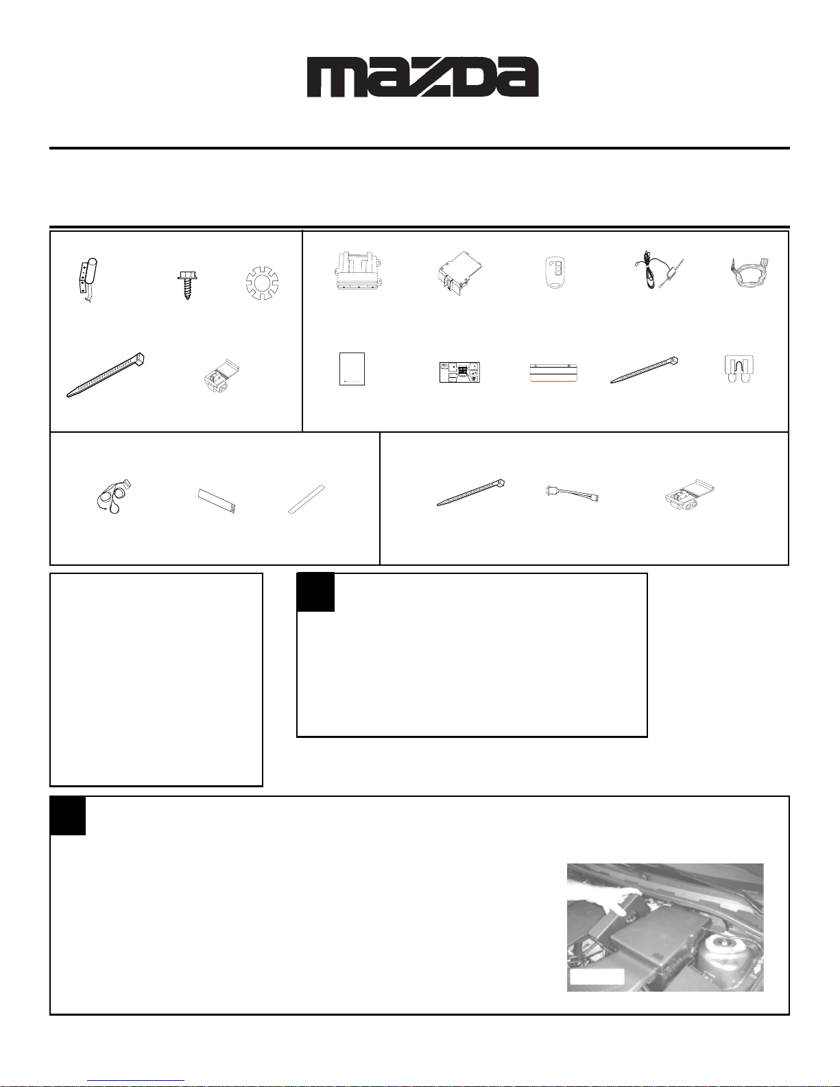
HOOD SAFETY SWITCH KIT CONTENTS
(P/N: 0000-8F-H03)
& L10A
GENUINE ACCESSORIES
REMOTE START SYSTEM
WITH VEHICLE SECURITY
AND KEYLESS ENTRY
KIT CONTENTS
APPLICABLE MODELS:
2004>MAZDA3
All Models With
Power Door Locks
!
LO
CK
UN
LO
CK
START
Hood Safety
Switch
(QTY 1)
1/4” Self
Drilling Screws
(QTY 2)
Locking
Washer
(QTY 2)
Remote Start DNA Card Remote Start Dipole Antenna Remote Start
Control Module (QTY-1) Transmitters (QTY-1) Wire Harness
(QTY-1) (QTY-2) (QTY-1)
P/N: 0000-8F-Z01 P/N: 0000-8F-L16 P/N: 0000-8F-F06 P/N: 0000-8F-Z10 P/N: 0000-8F-L02
Owners
Tie Wrap
(QTY 2)
IDC Wire Tap
(QTY 2)
Manual
(QTY 1)
IMMOBILIZER INTERFACE KIT CONTENTS
(P/N: 0000-8F-H05)
Immobilizer Interface Adhesive Primer 2- Sided Tape
Module and Harness (QTY-1) (QTY-1)
(QTY-1)
TOOLS REQUIRED
SAFETY GLASSES
0
ELECTRICAL TAPE
WIRE CUTTERS
PLIERS
ALCOHOL or GLASS CLEANER
PHILLIPS SCREWDRIVER
POWER DRILL
9/32” DRILL BIT
FIBER STICK
10mm SOCKET AND RATCHET
1/4” SOCKET AND DRIVE
3/8” DRIVE TORQUE WRENCH
3/8” DRIVE 10mm SOCKET
MAZDA
GENUINE ACCESSORIES
Vehicle Remote Start System
Owner's Manual
Featuring PowerCode Technology
TM
TM
For the Ultimate in Comfort, Convenience and Security
Wallet
Card
(QTY 1)
WARNING: / AVERTISSEMENT
This vehicle is equipped with a remote controlled engine starter.
To reduce the risk of serious Injury or death, switch engine starter
system into service mode and disconnect the vehicle battery
before performing any service on the vehicle.
Ce véhicule est doté d'un démarreur à distance. Pour réduire les
risques de blessures graves ou mortelles, mettre le démarreur à
distance en mode service et débrancher la batterie du véhicule
avant d'effectuer des travaux d'entretien sur celui-ci.
Underhood
Sticker
(QTY 1)
PARTS BAG CONTENTS
Tie Wrap LED IDC Wire Tap
(QTY-10) (QTY-1) (QTY-7)
PRE INSTALLATION
1. CLEAN HANDS
2. OPEN DRIVER’S DOOR WINDOW
3. RECORD RADIO STATIONS
4. SET PARKING BRAKE
5. DISCONNECT AND ISOLATE
NEGATIVE BATTERY TERMINAL
6. VEHICLE MUST BE AT ROOM
TEMPERATURE
Long Tie
Wrap
(QTY 3)
Mini Fuses
(QTY - (1) 5 AMP)
(QTY - (7) 15 AMP)
VEHICLE PREPARATION
1
1. Disconnect negative battery terminal:
a. Remove relay cover by grasping rear of cover and pulling upwards.
Disengage locking tabs and remove cover. (FIGURE A)
b. Disengage locking tabs and remove cover the battery cover.
c. Disconnect negative battery terminal and isolate.
FIGURE A
1
1031012 Rev.A 09/05
1
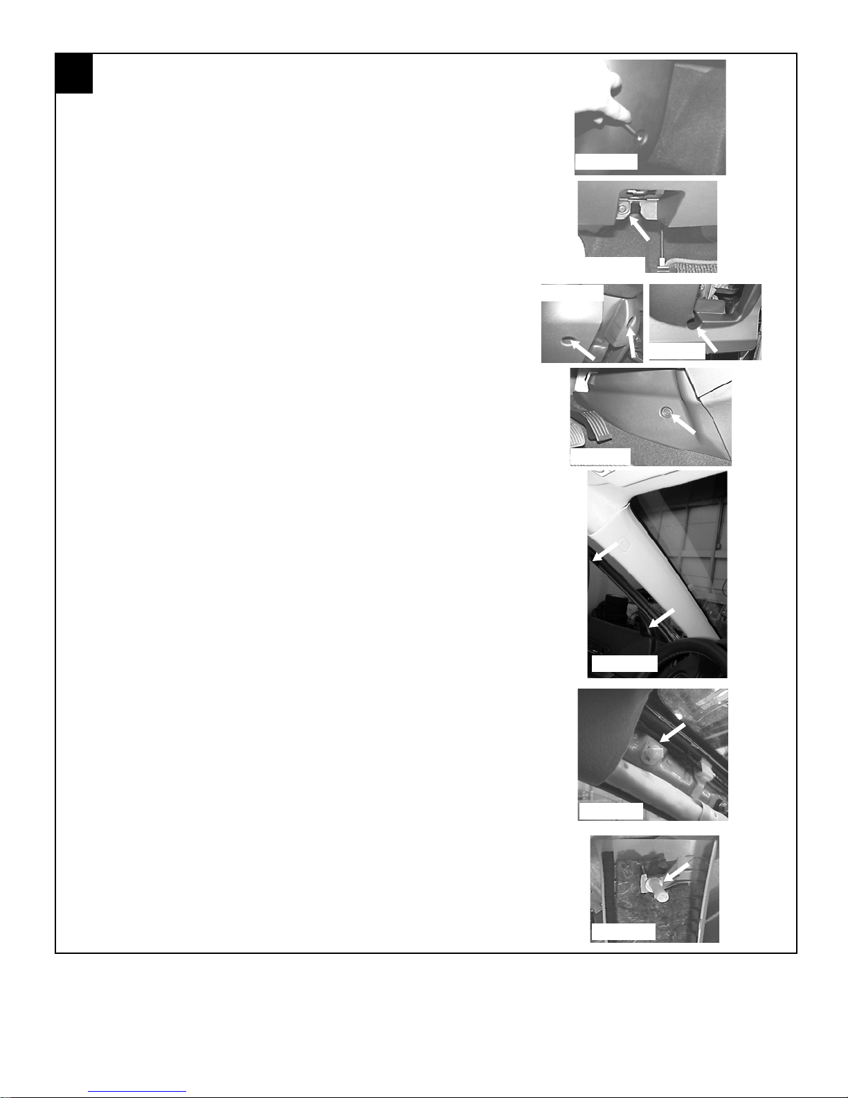
VEHICLE PREPARATION, continued
2. Remove the following components:
a. Using a fiber stick remove the driver’s side scuff plate.
b. Remove the driver’s side kick panel by using a fiber stick
pull the plastic center button of the plastic fastener out to disengage (FIGURE B). Gently pull the kick panel towards the
rear of the vehicle to remove.
c. Unclip the hood release by inserting a fiber stick between the
hood release and the dash panel. There is a center tab the
stick must push down while pulling the hood release towards
the rear of the vehicle.
d. Remove one (1) phillips screw behind the hood release handle.
(FIGURE C)
e. Carefully pull the rubber weather seal away from the door jamb
along the lower dashboard panel. Unclip the lower dash panel
using a fiber stick starting at the bottom and unplug any connectors attached to the panel.
f. Remove the three (3) phillips head screws from the lower steer-
ing column shroud, and remove the shroud. (FIGURE D and
E)
g. Remove the lower center console kick panels from both driver
and passenger sides by using a fiber stick to pull the plastic
center button of the plastic fastener out to disengage (FIGURE F). Gently pull the kick panel towards the rear of the
vehicle to remove.
FIGURE B
FIGURE C
FIGURE D
FIGURE E
FIGURE F
h. Remove the driver’s side A-pillar panel being careful not to
damage the retaining clips or the curtain airbag. Carefully pull
the rubber weather seal away from the door jamb (FIGURE
G) then, starting at the top of the panel, pull the A-pillar panel
toward the inside of the car but DO NOT try to pull all the way
off. There is a white clip at the top which only releases about
an inch then the panel must be slid off of it by pulling upward.
Be very careful not to damage the head liner or break the
white top clip.
i. Push the white top clip back into the A-pillar half way until it
rotates freely.
j. turn the white top clip diagonally and pull straight out of the A-
pillar. (FIGURE H)
k. Slide the removed white clip into position on the A-pillar panel.
(FIGURE I)
FIGURE G
FIGURE H
FIGURE I
2
1031012 Rev.A 09/05
2
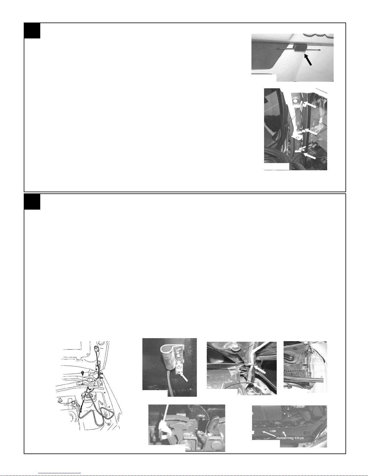
1. Clean mounting spot with an alcohol pad prior to mounting. Mount
DIPOLE ANTENNA MOUNTING
the dipole antenna to the windshield 210mm to the right of center on
the windshield, directly below the black windshield trim material. (FIGURE J)
2. Run the antenna wire above the headliner to the driver’s A-pillar,
using a fiber stick to secure under the headliner.
Note: Make sure the antenna wire is secure under the head
liner, if necessary remove the sun visor to secure.
3. Route the antenna wire down the A-pillar securing it to the existing
wiring using (3) supplied tie wraps. Do not secure it directly to the
sunroof drain tube or airbag. (FIGURE K)
4. Route the antenna wire behind the left side of the dashboard. The
antenna will be connected to the remote start control module later.
5. Re-install the driver’s side A-pillar panel and re-install the weather
seal along the A-pillar.
3
1. Using (2) supplied 1/4” self drilling screws and (2) supplied lock washers, secure the hood safety switch to
2. Route the hood safety switch wiring down into the engine compartment along the inside of the hood hinge
HOOD SAFETY SWITCH MOUNTING
the drivers side of the vehicle’s hood 95mm below the drain hole and 60mm from the side edge. (FIGURE
L & M)
and secure using (2) supplied tie wraps. (FIGURE L & N)
FIGURE J
FIGURE K
3. Route the hood safety switch wiring along the cowl panel, tucking under the cowl panel where possible, into
the engine compartment towards the hood release cable grommet. (FIGURE L & O)
4. Disengage hood latch cable and pull through radiator support bracket.
CAUTION: Failure to secure hood latch open with a tie wrap could allow the hood to become
locked without the hood release cable available.
a. Attach a tie wrap to the hood latch mechanism. (FIGURE P)
b. Disconnect the hood latch cable at latch.
c. Free the hood latch cable from (2) retaining clips. (FIGURE Q)
FIGURE L
FIGURE M
FIGURE N
FIGURE O
FIGURE P
FIGURE Q
3
1031012 Rev.A 09/05
3
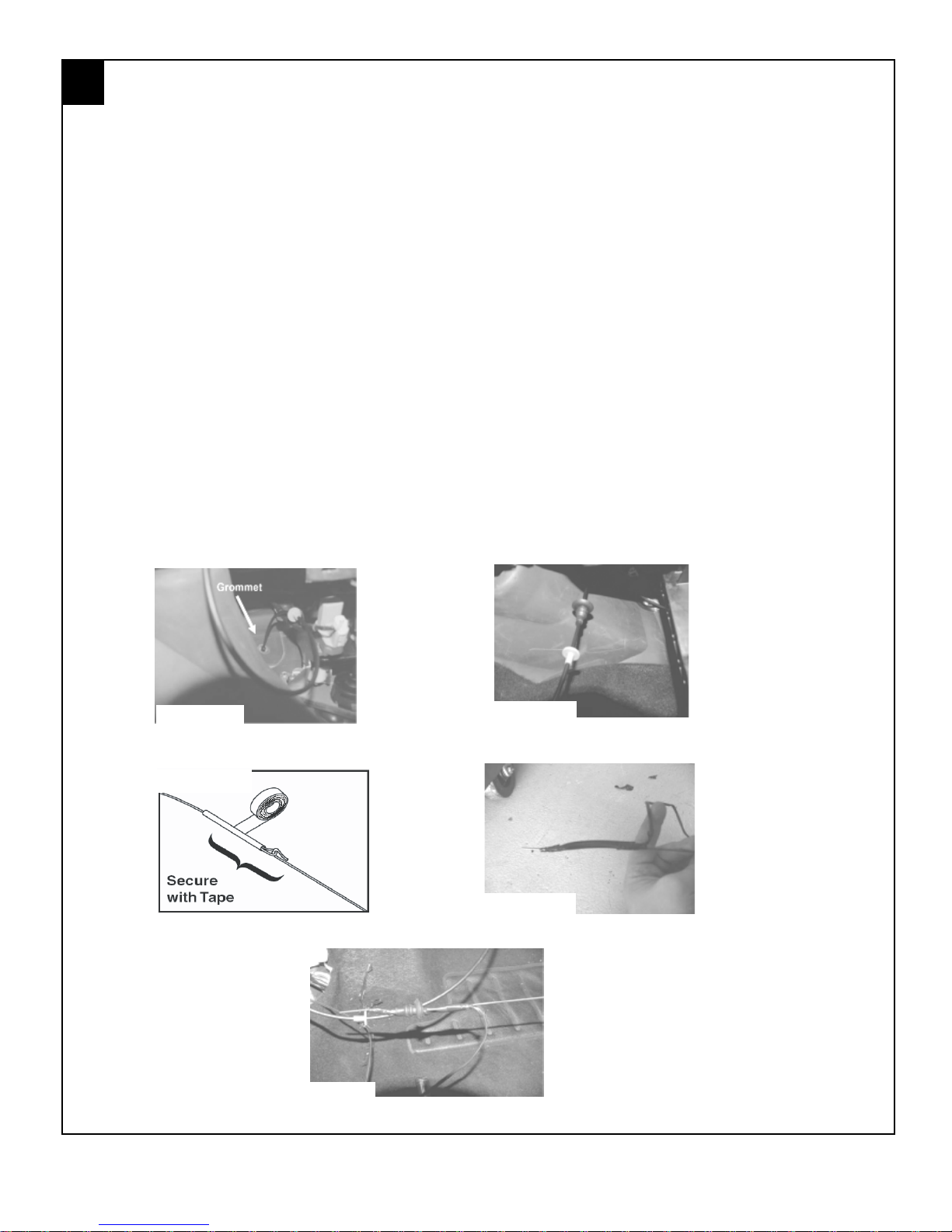
HOOD SAFETY SWITCH MOUNTING CONTINUED
5. Locate the hood release cable grommet from inside the occupant compartment. (FIGURE R)
6. Pull the hood release cable and grommet approximately 20” into the driver’s side footwell.
(FIGURE S)
7. Using fish wire, pull the hood safety switch wiring through the hood release cable opening:
a. From inside of the vehicle, insert the fish wire through the hood release cable opening.
b. Bend approximately three (3) inches of harness at wire end.
c. Using electrical tape, secure fish wire to harness as shown. (FIGURE T)
d. Pull fish wire and wiring through hood release cable opening. (FIGURE L, page 3)
e. Tape the hood safety switch wires against the fish wire and electrical tape in place. (FIGURE U)
f. Slide the fish wire and wiring through the hood release grommet and pull the excess wiring
through the grommet. (FIGURE V)
8. Reconnect the hood release cable:
a. Pull the hood release cable back into position. Reattach to hood latch release mechanism and
two (2) retaining clips. (NOTE: Ensure the hood latch cable retaining collar is seated securely).
b. Remove the tie wrap from the hood latch release mechanism.
c. Slide the hood release cable grommet back into position in the vehicle dashwall.
FIGURE R
FIGURE T
FIGURE S
FIGURE U
FIGURE V
4
1031012 Rev.A 09/05
4
S
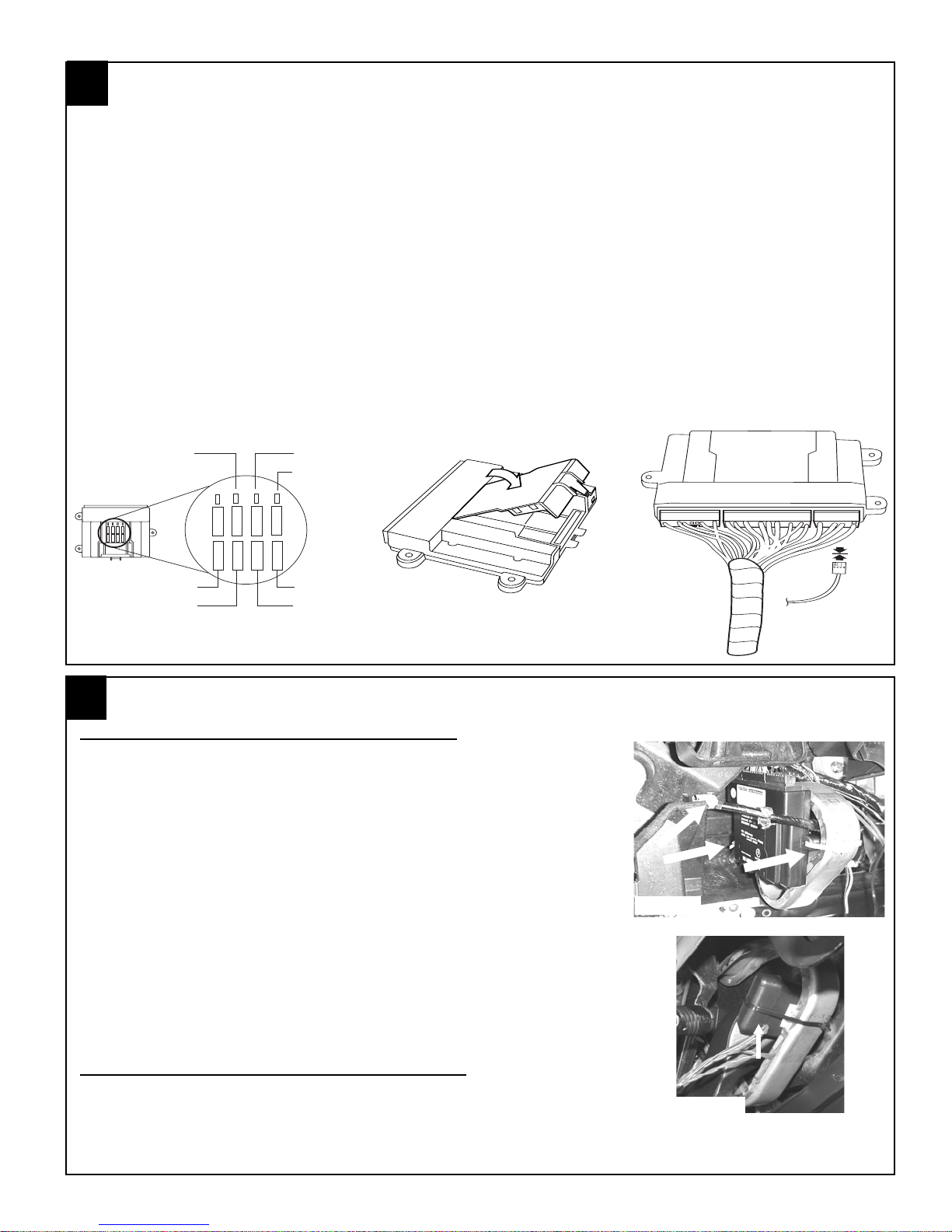
REMOTE START CONTROL MODULE PREPARATION
1. Insert the supplied fuses into the remote start control module as shown in below (FIGURE W).
the fuses fit tight so use a tool handle to seat them in place if necessary.
2. Install DNA card into the remote start control module as shown below. (FIGURE X)
NOTE: Use care to assure that both rows of the multipin connectors are aligned and seated properly.
3. Plug the supplied wire harness 10-way, 24-way and 16-way connectors into the remote start control
module (FIGURE Y). Make sure the harnesses are seated completely. NOTE: The connectors will only
plug into the remote start control module one way.
4. Plug the supplied immobilizer interface 4-way connector into the remote start control module. (FIGURE
Y)
NOTE: TAPE OFF THE WHITE WIRE (IF EQUIPPED) COMING FROM THE 4-WAY CONNECTOR
(THIS WIRE IS NOT USED ON THIS SYSTEM).
15
15
5
15
PK LIGHTS
DOOR LOCK
-+
MAIN B+
IGNITION
FIGURE X
5
DOME LIGHT
TRUNK RELEASE
15
15
15
15
15
15
5
15
15
15
HVAC 1
HVAC 2
-+
15
15
FIGURE W
REMOTE ENGINE START MODULE AND IMMOBILIZER INTERFACE MOUNTING
REMOTE ENGINE START MODULE MOUNTING
1. Locate the large dashboard support bracket to the left of the steering
column.
2. Using a fiber stick to temporarily release the white harness fastener
to the left of the dashboard support brace to allow for easy placement of the remote engine start control module. (FIGURE Z)
3. Using (2) supplied long tie wraps secure the remote start control
module to the left side of the dashboard support bracket. Make sure
that the remote start control module is not mounted to far down on
the bracket, this will eliminate problems with dashboard reassembly. (FIGURE Z)
FIGURE Z
Tie Wraps
To Immobilizer
Interface Module
FIGURE Y
4. Route the dipole antenna cable (previously installed in step 2)
and plug into the 2-pin connector on the bottom of the remote
start control module.
IMMOBILIZER INTERFACE MODULE MOUNTING
1. Locate the Large dashboard support bracket to the right of the
steering column.
2. Using (1) supplied long tie wraps, secure the immobilizer interface to
the dashboard bracket. (FIGURE AA)
FIGURE AA
5
1031012 Rev.A 09/05

6
1. Locate the BLACK/ORANGE and GRAY/RED wire from the remote start system harness.
2. Locate the wires listed below. If the hood safety switch wire has a ground ringlet terminal or a stripped end
3. Using the (2) supplied IDC wire taps (in hood safety switch parts bag), connect the switch wires listed
HOOD SAFETY SWITCH MOUNTING WIRE CONNECTIONS
on either wire then cut the ends of the wires so they are blunt.
below together and crimp the IDC wire tap in place using pliers, assure that a complete and secure
connection is made.
HOOD SAFETY SWITCH WIRE REMOTE START HARNESS WIRE
Dk. GRAY GRAY/RED
Dk. GRAY BLACK/ORANGE
NOTE: Switch is not polarity sensitive.
7
1. Locate the 10mm factory ground lug located in the driver’s kick panel area.
2. Using a 10mm ratchet remove the 10mm lug bolt.
3. Re-secure the factory ground ringlet and remote start harness BLACK/
GROUND CONNECTION
(FIGURE BB)
ORANGE ground wire with ringlet and tighten with a 10mm ratchet. (FIGURE CC)
NOTE: USING A 3/8” DRIVE TORQUE WRENCH MAKE SURE
THAT THE 10mm GROUND LUG BOLT IS SECURELY TIGHTEN 78-121 INCH/POUNDS.
FIGURE BB
FIGURE CC
6
1031012 Rev.A 09/05
 Loading...