

Mazda 6 2006, 0000-8F-H13 Instructions Manual
®
BOTH PROGRAMMED IGNITION
30
sec.
2 sec.
5X
2 sec.
KEYS ARE REQUIRED AT TIME
OF INSTALLATION
INSTALLATION INSTRUCTIONS
P ART NUMBER (s):
0000-8F-H13
HOOD SAFETY SWITCH KIT CONTENTS
(P/N: 0000-8F-H03)
GENUINE ACCESSORIES
REMOTE START SYSTEM
KIT CONTENTS
APPLICABLE MODELS:
2006>MAZDA6
ALL MODELS
Hood Safety
Switch
(QTY 1)
Tie Wrap
(QTY 2)
1/4” Self
Drilling Screws
(QTY 2)
IDC Wire T ap
(QTY 2)
Locking
Washer
(QTY 2)
Remote Start DNA Card Remote Start Dipole Antenna Remote Start
Control Module (QTY-1) Transmitters (QTY-1) Wire Harness
(QTY-1) (QTY-2) (QTY-1)
P/N: 0000-8F-Z01 P/N: 0000-8F-H16 P/N: 0000-8F-Z02 P/N: 0000-8F-Z10 P/N: 0000-8F-H17
IMMOBILIZER INTERFACE KIT CONTENTS
(P/N: 0000-8F-H05)
Immobilizer Interface Adhesive Primer 2- Sided Tape
Module and Harness (QTY-1) (QTY-1)
(QTY-1)
TOOLS REQUIRED
SAFETY GLASSES
ELECTRICAL T APE
WIRE CUTTERS
PLIERS
ALCOHOL or GLASS CLEANER
PHILLIPS SCREWDRIVER
POWER DRILL
9/32” DRILL BIT
FIBER STICK
10mm SOCKET AND RATCHET
8mm SOCKET AND RATCHET
1/4” SOCKET AND DRIVE
3/8” DRIVE TORQUE WRENCH
3/8” DRIVE 10mm SOCKET
MAZDA
GENUINE ACCESSORIES
Vehicle Remote Start System
Owner's Manual
TM
Featuring PowerCode Technology
TM
For the Ultimate in Comfort, Convenience and Security
Owners
Manual
(QTY 1)
WARNING: / AVERTISSEMENT
This vehicle is equipped with a remote controlled engine starter.
To reduce the risk of serious Injury or death, switch engine starter
system into service mode and disconnect the vehicle battery
before performing any service on the vehicle.
Ce véhicule est doté d'un démarreur à distance. Pour réduire les
risques de blessures graves ou mortelles, mettre le démarreur à
distance en mode service et débrancher la batterie du véhicule
avant d'effectuer des travaux d'entretien sur celui-ci.
Wallet
Card
(QTY 1)
Underhood
Sticker
(QTY 1)
Long Tie
Wrap
(QTY 4)
Mini Fuses
(QTY - (1) 5 AMP)
(QTY - (7) 15 AMP)
P ARTS BAG CONTENTS
Tie Wrap IDC Wire Tap
(QTY-10) (QTY-4)
0
PRE INST ALLA TION
1. CLEAN HANDS
2. OPEN DRIVER’S DOOR WINDOW
3. RECORD RADIO ST ATIONS
4. SET PARKING BRAKE
5. DISCONNECT AND ISOLATE
NEGA TIVE BATTERY TERMINAL
6. VEHICLE MUST BE AT ROOM
TEMPERATURE
1
VEHICLE PREP ARATION
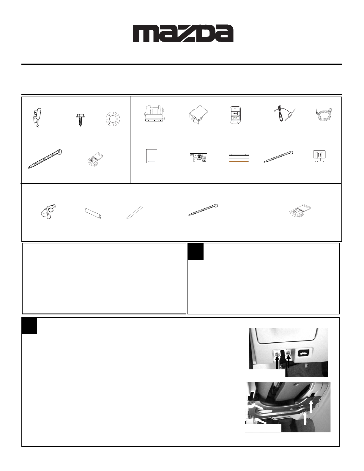
1. Remove the driver’s side lower dash panel.
a. Unclip the hood release by inserting a fiber stick between the
hood release and the dash panel. There is a center tab the
stick must push down while pulling hood release towards the
rear of the vehicle.
b. Remove (2) 8mm bolts behind the hood release cable.
(FIGURE A)
c. Unsnap lower dash panel using a fiber stick starting at the
bottom.
d. Unplug the trunk release connector after removing the lower
dash panel.
2. Remove the driver’s side lower dash kneeblocker bracket (4) phil-
lips head screws and remove bracket. (FIGURE B)
FIGURE A
FIGURE B
1
1030832 Rev.A 10/05
1
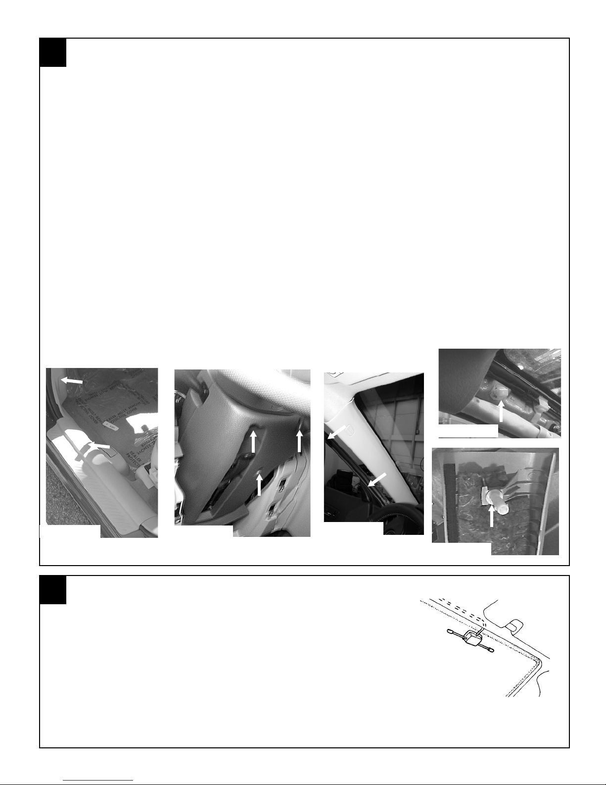
3. Using a fiber stick, remove the driver’s side scuff plate and driver’s side kick panel cover. (FIGURE
4. Remove the lower steering column shroud.
5. Remove the driver’s side A-pillar panel being careful not to damage the retaining clips or the
6. Push the white top clip back into the A-pillar half way until it rotates freely.
7. Turn the white top clip diagonally and pull straight out of the A-pillar. (FIGURE F)
8. Slide the removed white clip into position on the A-pillar panel. (FIGURE G)
VEHICLE PREPARATION, continued
C)
a. Remove (3) phillips head screws (1 dark machine head, 2 gold coarse thread). Note that the (2)
course screws go in the (2) holes closest to the steering wheel. (FIGURE D)
b. The top half of the shroud is connected to the dash and does not need to be totally removed but
the key courtesy light does need to be removed before the bottom is pulled away from the
steering column.
curtain airbag. Carefully pull the rubber weather seal away from the door jamb (FIGURE E) then,
starting at the top of the panel, pull the A-pillar panel toward the inside of the car but DO NOT try to
pull all the way off. There is a white clip at the top which only releases about an inch then the panel
must be slid off of it by pulling upward. Be very careful not to damage the head liner or break the
white top clip.
FIGURE C
2
1. Clean the mounting location with an alcohol pad prior to mount-
2. Run the antenna wire above the headliner to the driver’s A-pil-
DIPOLE ANTENNA MOUNTING
ing. Mount the dipole antenna to the windshield 8” (205 mm) to
the right of center on the windshield and below the black windshield trim so that the antenna will not interfere with potential
addition of EC mirror harness. (FIGURE H)
lar, using a fiber stick to secure under the headliner.
FIGURE D
FIGURE E
FIGURE F
FIGURE G
FIGURE H
Note: Make sure the antenna wire is secure under the headliner.
If necessary remove the sun visor to secure.
2
1030832 Rev.A 10/05
2
3. Route the antenna wire down the A-pillar securing it to the exist-
4. Route the antenna wire behind the left side of the dashboard.
5. Carefully reinstall A-pillar panel. There are 2 tangs on the
DIPOLE ANTENNA MOUNTING , continued
ing wiring using (3) of the supplied tie wraps. Do not secure it
directly to the sunroof drain tube or airbag. (FIGURE I)
The antenna will be connected to the remote start control module later.
bottom of the panel that need to be inserted into the slots at
the bottom of the A-pillar.
Note: Be very careful not to break the white clip off or
damage the headliner while reinstalling the A-pillar
panel. Once reinstalled correctly the panel will fit tight
to the headliner. If there are gaps at the top between
the panel and headliner then the white clip is not
seated correctly.
3
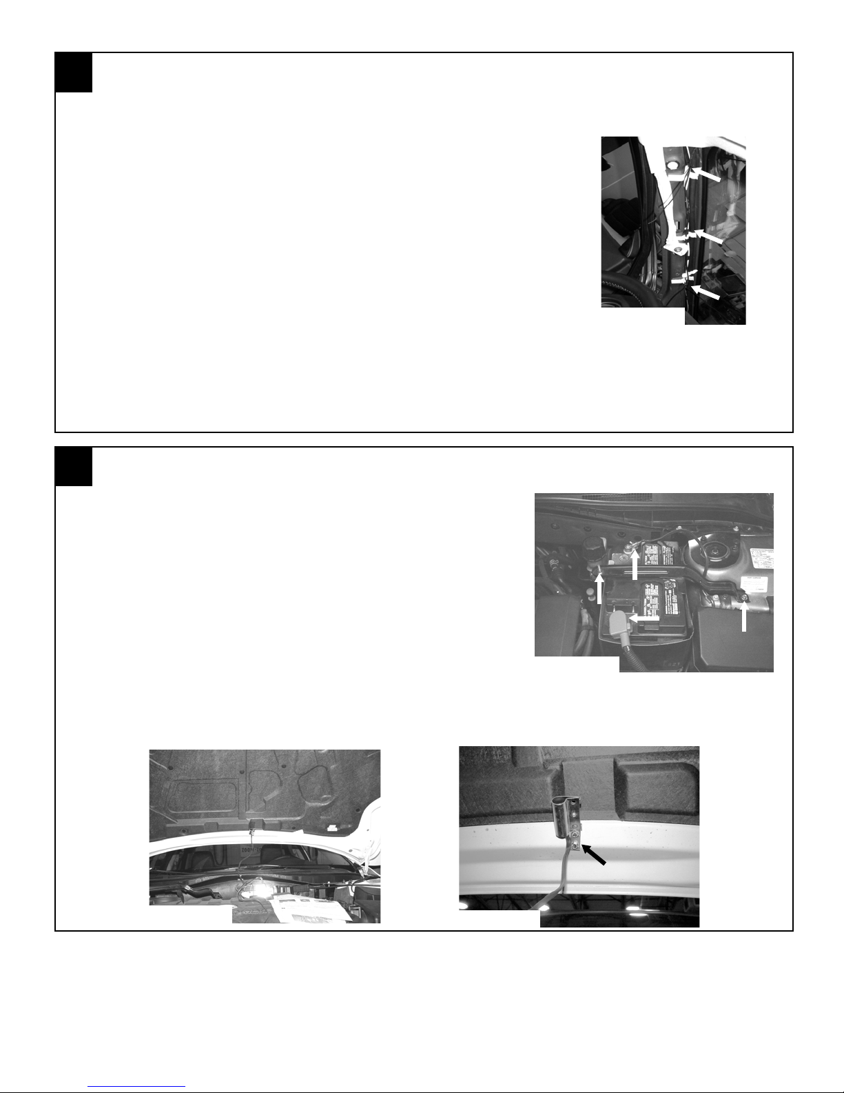
1. Remove the vehicle’s battery
2. Using the supplied (2) 1/4” self drilling screws and (2) lock washers, secure the hood safety switch
HOOD SAFETY SWITCH MOUNTING
a. Loosen the nuts on the positive and battery terminal.
(FIGURE J)
b. Disconnect and isolate the positive battery cable.
c. Remove the 10mm bolt securing the right side of the bat-
tery bracket to the shock tower. (FIGURE J)
d. Loosen the nut securing the left side battery bracket.
(FIGURE J)
e. Remove the battery bracket.
f. Carefully remove the vehicle’s battery and set aside in a
safe place to prevent damage.
to the vehicle’s hood 2’3.5” (710mm) from the edge of the hood, measuring from the driver’s side.
(FIGURE K & L)
FIGURE J
FIGURE I
FIGURE K
FIGURE L
3
1030832 Rev.A 10/05
3
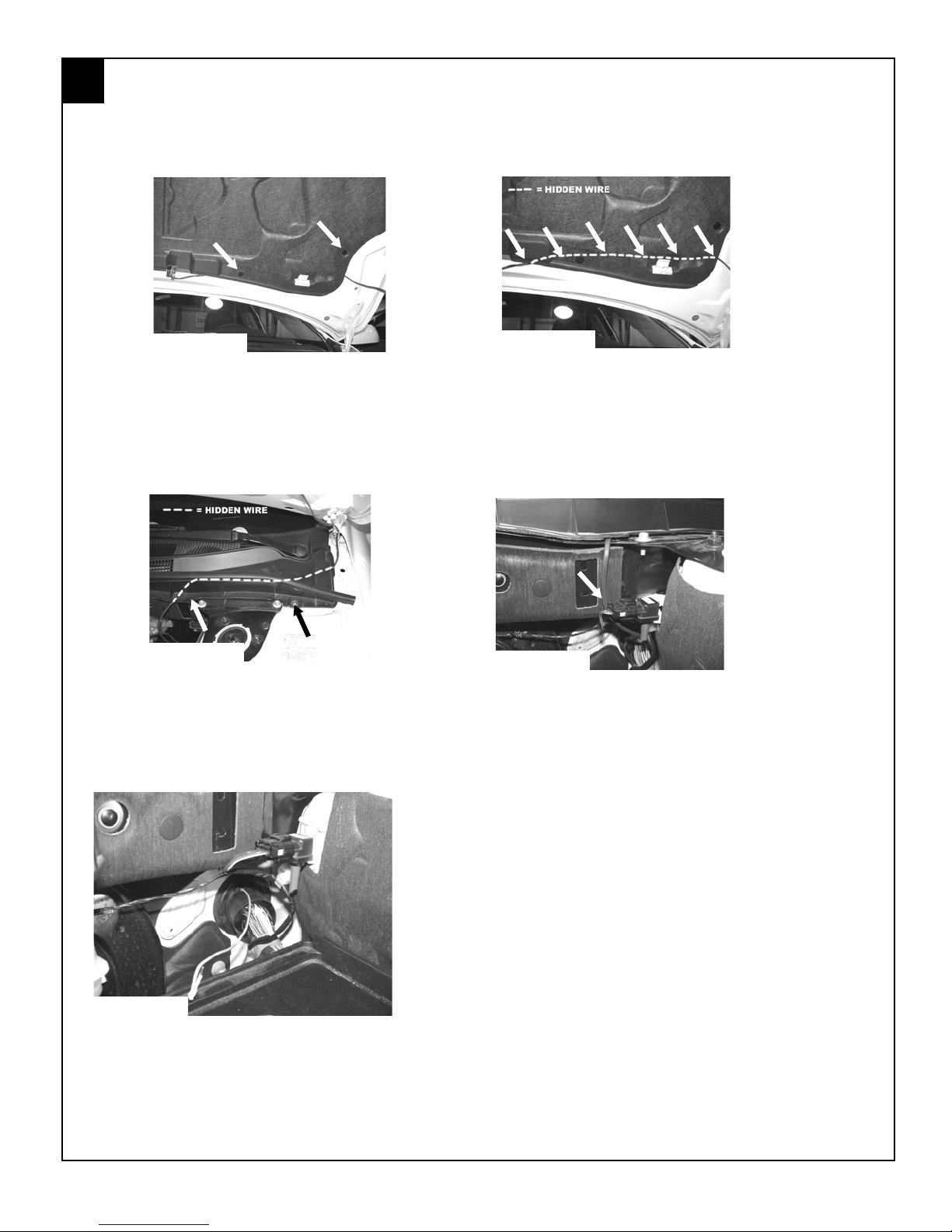
3. Remove (2) push pins from driver’s side of hood insulation (FIGURE M). Tuck the wiring from the
HOOD SAFETY SWITCH MOUNTING, continued
hood safety switch under the hood insulation and route towards the driver’s side of the hood.
(FIGURE N)
FIGURE M
4. Using one of the supplied tie wraps, secure the wiring to the engine side of hood bracket. (FIGURE
O) Remove screw and plastic screw retainer assembly from bottom edge of cowl trim panel (be
careful not to loose plastic screw or retainer clip). (FIGURE O) Route hood safety switch wire
under plastic cowl trim panel as shown. (FIGURE O) Replace previously removed screw plastic
retainer assembly. Route hood switch safety wire behind MAP sensor. (FIGURE P) Reinstall screw
and plastic screw retainer assembly in bottom edge of cowl trim panel, insure that plastic retainer
assembly is fully seated.
FIGURE O
5. Carefully pierce hole in the top of main bulkhead harness grommet from engine compartment into
the passenger compartment. Place wire-fish through hole from passenger compartment out into
engine compartment. (FIGURE Q) Tape hood safety switch to wire-fish and gently pull wire through
hole in bulkhead grommet and release wire from wire-fish. Seal hole with silicone and re-install
the vehicle’s battery.
FIGURE N
FIGURE P
FIGURE Q
Caution: Do not attempt to pierce or route wire
through center section of grommet with OEM wires
which are protected with dielectric grease.
4
1030832 Rev.A 10/05
4
S
REMOTE START CONTROL MODULE PREPARATION
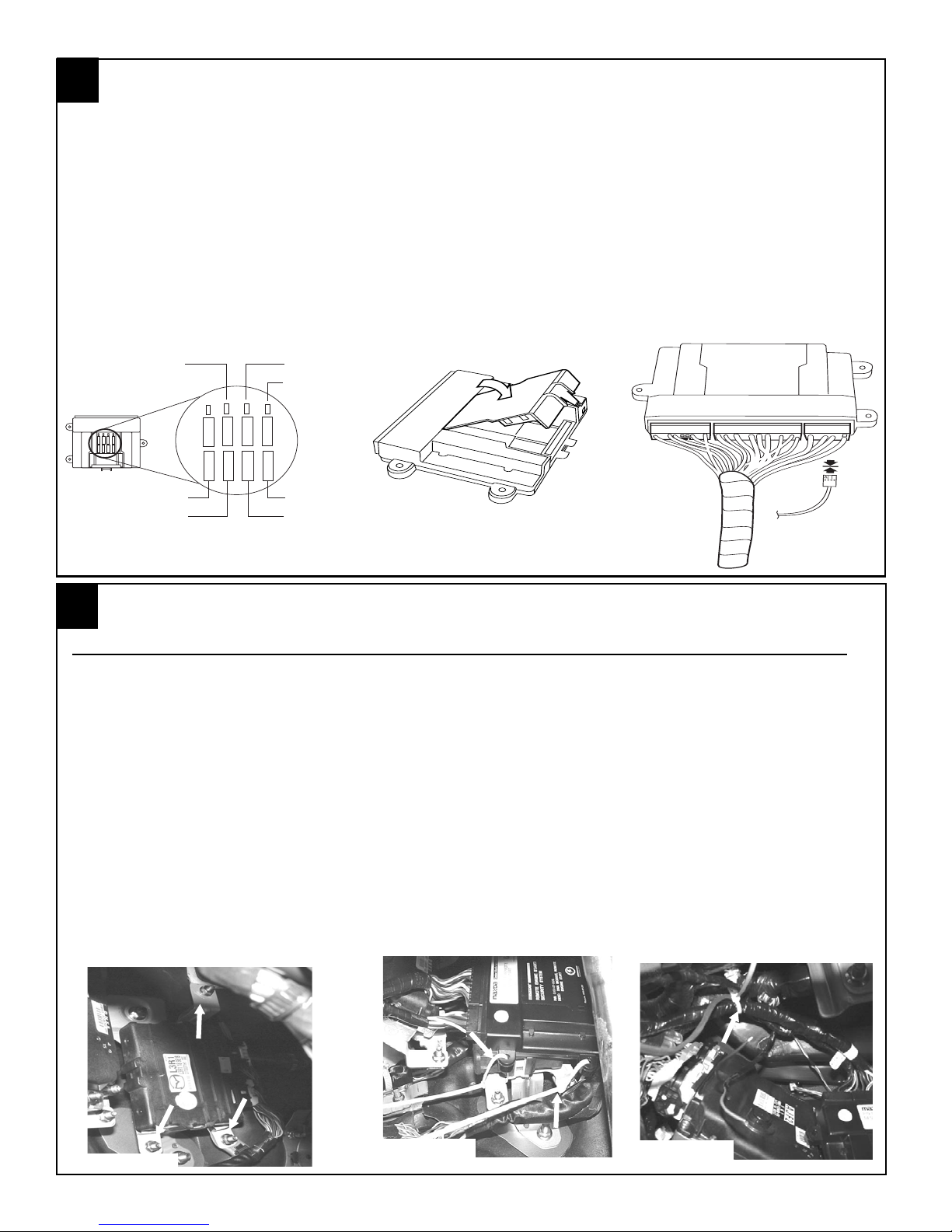
1. Insert the supplied fuses into the remote start control module as shown in below (FIGURE R).
The fuses fit tight so use a tool handle to seat them in place if necessary.
2. Install DNA card into the remote start control module as shown below. (FIGURE S)
3. Plug the supplied wire harness 10-way and 24-way and connectors into the remote start control
module (FIGURE T). Make sure the harnesses are seated completely.
4. Plug the supplied immobilizer interface 4-way connector into the remote start control module.
(FIGURE T)
NOTE: TAPE OFF THE WHITE WIRE (IF EQUIPPED) COMING FROM THE 4-WAY CONNECTOR (THIS WIRE IS NOT USED ON THIS SYSTEM).
15
15
5
15
PK LIGHTS
DOOR LOCK
-+
MAIN B+
IGNITION
FIGURE S
To Immobilizer
Interface Module
DOME LIGHT
TRUNK RELEASE
15
15
15
15
5
15
15
15
HVAC 1
HVAC 2
FIGURE R
15
15
-+
15
15
FIGURE T
5
REMOTE ENGINE START MODULE AND IMMOBILIZER INTERFACE MOUNTING
REMOTE ENGINE START MOUNTING, VEHICLE’S EQUIPPED WITH I-4 ENGINE
1. Route the 2-pin dipole antenna connector (previously installed in step 2) to the remote engine
start control module and plug into the 2-pin port on the back side of the module.
2. Find the black TCM module mounted against the bulkhead (over the clutch hole knockout)
secured with a silver mounting bracket to the left of the brake pedal.
3. Using (3) of the supplied long tie wraps secure the remote start control module to the TCM
module fastening the tie wraps around the upper and lower legs of the bracket which are
pointed out below (FIGURE U & V) by the arrows.
a. The remote engine start module wiring should run out towards the driver’s side door.
NOTE: Make sure the remote start control module is securely mounted on the TCM module so
that it does not rattle and the remote start module connectors are facing towards the driver’s
door. The harness should then be routed towards the driver’s kick p anel area as shown below
and secured to existing vehicle wiring using (1) supplied tie wrap. (FIGURE W).
FIGURE U
FIGURE V
FIGURE W
5
1030832 Rev.A 10/05
5
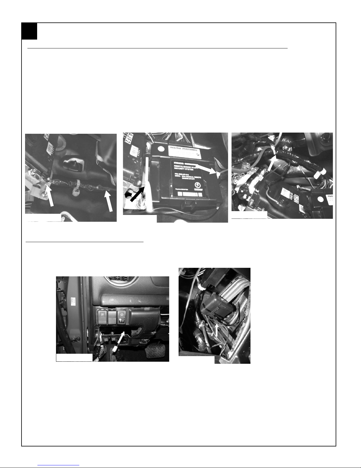
REMOTE ENGINE START MOUNTING, VEHICLE’S EQUIPPED WITH V-6 ENGINE
1. Route the 2-pin dipole antenna connector (previously installed in step 2) to the remote engine
2. Using (2) of the supplied long tie wraps secure the remote start control module to the PCM
REMOTE ENGINE START MODULE AND IMMOBILIZER INTERFACE MOUNTING
start control module and plug into the 2-pin port on the back side of the module.
bracket on the left side and the large vehicle wire harness on the right side. (FIGURE X & Y)
NOTE: Make sure the remote start control module is securely mounted so that it does not rattle
and the remote start module connectors are facing upwards. The harness should then be routed
towards the driver’s kick panel area as shown below and secured to existing vehicle wiring using
(1) supplied tie wrap. (FIGURE Z).
FIGURE X
IMMOBILIZER INTERFACE MODULE
1. Using (1) supplied long tie wraps secure the immobilizer interface to the bracket to the left of the steering
column. (FIGURES AA & BB)
FIGURE AA
FIGURE Y
FIGURE BB
FIGURE Z
6
1030832 Rev.A 10/05
 Loading...