


COMMERCIAL HE DRYER INSTALLATION INSTRUCTIONS (original instructions)
Gas
INSTRUCTIONS D’INSTALLATION D’UN SECHE-LINGE HE COMMERCIAL (traduction des instructionsd’origine)
À gaz
INSTRUCCIONES DE INSTALACIÓN– SECADORA HE COMERCIAL (traducciónde las instrucciones originales)
A gas
ISTRUZIONID’INSTALLAZIONE – ASCIUGATRICEHE COMMERCIALE (traduzione delle istruzioni originali)
A gas
MDG22PN |
MDG22PD |
W10239207B
www.maytagcommerciallaundry.com

TABLE OF CONTENTS
DRYER SAFETY ............................................................................ |
3 |
DRYER DISPOSAL ........................................................................ |
4 |
INSTALLATION REQUIREMENTS ............................................. |
4 |
Tools and Parts .......................................................................... |
4 |
Location Requirements ............................................................. |
4 |
Electrical Requirements - Gas Dryer.......................................... |
5 |
Gas Supply Requirements ....................................................... |
6 |
Venting Requirements ................................................................ |
7 |
INSTALLATION INSTRUCTIONS – GAS DRYER |
....................9 |
Install Leveling Legs.................................................................... |
9 |
Make Gas Connection................................................................ |
9 |
Connect Vent .............................................................................. |
9 |
Complete Installation ................................................................ |
9 |
MAINTENANCE INSTRUCTIONS .......................................... |
10 |
TECHNICAL SPECIFICATIONS – GAS DRYER...................... |
10 |
REVERSING THE DOOR SWING (OPTIONAL)....................... |
11 |
ELECTRONIC CONTROL SETUP .......................................... |
13 |
WARRANTY.............................................................................. |
17 |
TABLE DES MATIERES
SECURITE DU SECHE-LINGE ................................................ |
18 |
ELIMINATION DU SECHE-LINGE .......................................... |
19 |
EXIGENCES D’INSTALLATION................................................ |
19 |
Outillage et pièces .................................................................... |
19 |
Exigences d’emplacement ...................................................... |
20 |
Spécifications électriques - sèche-linge à gaz ...................... |
21 |
Spécifications de l’alimentation en gaz .................................. |
22 |
Exigences concernant l’évacuation .......................................... |
23 |
INSTRUCTIONS D’INSTALLATION – |
|
SECHE-LINGE A GAZ .............................................................. |
24 |
Installation des pieds de nivellement........................................ |
24 |
Raccordement à la canalisation de gaz .................................. |
25 |
Raccordement du conduit d’évacuation ................................ |
25 |
Achever l’installation ................................................................ |
25 |
INSTRUCTIONS D’ENTRETIEN............................................... |
25 |
FICHE TECHNIQUE – SECHE-LINGE A GAZ ........................ |
26 |
INVERSION DU SENS D’OUVERTURE DE LA PORTE ......... |
27 |
REGLAGE DE LA CARTE |
|
DE CIRCUITS ELECTRONIQUES .......................................... |
29 |
GARANTIE ................................................................................ |
33 |
ÍNDICE
SEGURIDAD DE LA SECADORA............................................ |
34 |
ELIMINACIÓN DE LA SECADORA ......................................... |
35 |
REQUISITOS DE INSTALACIÓN ............................................ |
35 |
Piezas y herramientas .......................................................... |
35 |
Requisitos de ubicación........................................................ |
35 |
Requisitos eléctricos - secadora a gas ................................ |
36 |
Requisitos del suministro de gas............................................ |
37 |
Requisitos de ventilación .................................................... |
38 |
INSTRUCCIONES DE INSTALACIÓN – |
|
SECADORA A GAS ................................................................ |
40 |
Instalación de las patas niveladoras .................................... |
40 |
Conexión del suministro de gas............................................ |
40 |
Conexión del ducto de escape ............................................ |
40 |
Complete la instalación ........................................................ |
40 |
INSTRUCCIONES DE MANTENIMIENTO .............................. |
41 |
ESPECIFICACIONES TÉCNICAS – SECADORA A GAS ...... |
41 |
CÓMO INVERTIR EL SENTIDO DE APERTURA |
|
DE LA PUERTA ....................................................................... |
42 |
PROGRAMACIÓN DEL CONTROL ELECTRÓNICO ............ |
44 |
GARANTÍA................................................................................ |
48 |
INDICE
SICUREZZA DELL’ASCIUGATRICE ........................................ |
49 |
L’ELIMINAZIONE DELL’ASCIUGATRICE.................................. |
50 |
REQUISITI D’INSTALLAZIONE ................................................ |
50 |
Attrezzi e componenti............................................................. |
50 |
Requisiti di ubicazione ............................................................ |
50 |
Requisiti elettrici - asciugatrice a gas .................................... |
51 |
Requisiti di alimentazione del gas............................................ |
52 |
Requisiti di scarico ................................................................ |
53 |
ISTRUZIONI DI INSTALLAZIONE – ASCIUGATRICE |
|
A GAS ...................................................................................... |
55 |
Installazione dei piedini di regolazione .................................... |
55 |
Eseguire il colleganento gas .................................................... |
55 |
Connessione dello scarico ...................................................... |
55 |
Completamento dell’installazione............................................ |
56 |
ISTRUZIONI DI MANUTENZIONE ......................................... |
57 |
DATI TECNICI – ASCIUGATRICE A GAS .............................. |
57 |
INVERSIONE DELLA ROTAZIONE DI APERTURA ............... |
58 |
CONFIGURAZIONE DEI CONTROLLI ELETTRONICI .......... |
60 |
GARANZIA .................................................................................. |
64 |
2
DRYER SAFETY
Your safety and the safety of others are very important.
many important safety messages in this manual and on your appliance. Always read and obey all safety
safety alert symbol.
alerts you to potential hazards that can kill or hurt you and others.
messages will follow the safety alert symbol and either the word “DANGER” or “WARNING.” mean:
 DANGER
 WARNING
You can be killed or seriously injured if you don't immediately follow instructions.
You can be killed or seriously injured if you don't follow instructions.
All safety messages will tell you what the potential hazard is, tell you how to reduce the chance of injury, and tell you what can happen if the instructions are not followed.
FOR YOUR SAFETY
1.Do not use or store petrol or other flammable materials in this appliance or near this appliance.
2.Do not spray aerosols in the vicinity of this appliance while it is in operation.
3.Do not modify this appliance.
WARNING: For your safety, the information in this manual must be followed to minimize the risk of •re or explosion, or to prevent property damage, personal injury, or death.
–Do not store or use petrol or other €ammable vapors and liquids in the vicinity of this or any other appliance.
–WHAT TO DO IF YOU SMELL GAS:
•Do not try to light any appliance.
•Do not touch any electrical switch; do not use any phone in your building.
•Clear the room, building, or area of all occupants.
•Immediately call your gas supplier from a neighbor's phone. Follow the gas supplier's instructions.
•If you cannot reach your gas supplier, call the •re department.
–Installation and service must be performed by a quali•ed installer, service agency, or the gas supplier.
3
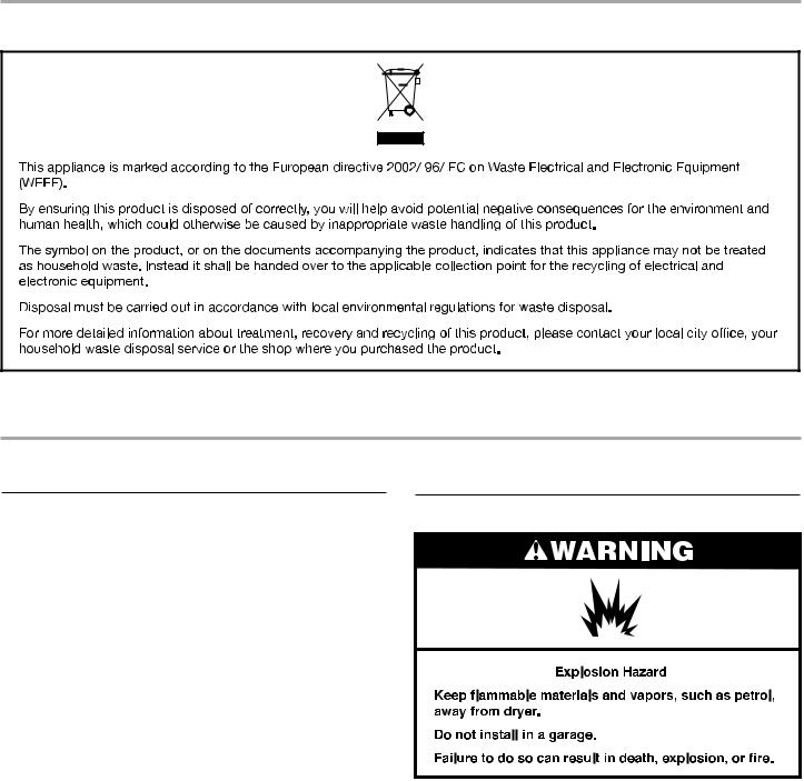
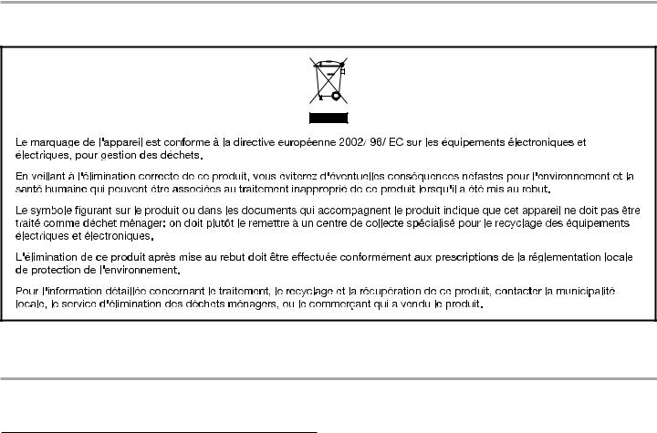
DRYER DISPOSAL
INSTALLATION REQUIREMENTS
Tools and Parts
Gather the required tools and parts before starting installation. Read and follow the instructions provided with any tools listed here.
Tools needed:
■200 mm (8") or 250 mm (10") Pipe wrench
■200 mm (8") or 250 mm (10") Adjustable wrench
■Flat-blade screwdriver
■Phillips screwdriver
■Adjustable wrench that opens to 25 mm (1") or hex-head socket wrench
■Level
Parts supplied:
■8 mm (5/16") socket wrench
■Utility knife
■Vent clamps
■Pipe-joint compound resistant to LP gas
■Sealing gun and sealing compound (for installing new exhaust vent)
■Pliers
■Stiff-bladed putty knife
Remove parts bag from dryer drum. Check that all parts were included.
■ |
Foot boot (4) |
■ PN models: Card reader |
■ |
Dryer foot (4) |
bezel, card reader wire |
|
harness, hardware
■ PD models: Cam for service door lock
NOTE: The circuit diagram for this dryer is located inside the lower front panel, within the Tech Sheets.
Location Requirements
If installing a gas dryer:
IMPORTANT: Observe all governing codes and ordinances.
■Check code requirements: Some codes limit or do not permit installation of clothes dryers in garages, closets, or sleeping quarters. Contact your local building inspector.
■Make sure that lower edges of the cabinet, plus the back and bottom sides of the dryer, are free of obstructions to permit adequate clearance of air openings for combustion air. See “Recessed Area and Closet Installation Instructions” below for minimum spacing requirements.
■Do not install on carpet.
NOTE: The dryer must not be installed in an area where it will be exposed to water and/or weather.
4
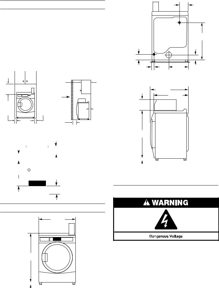
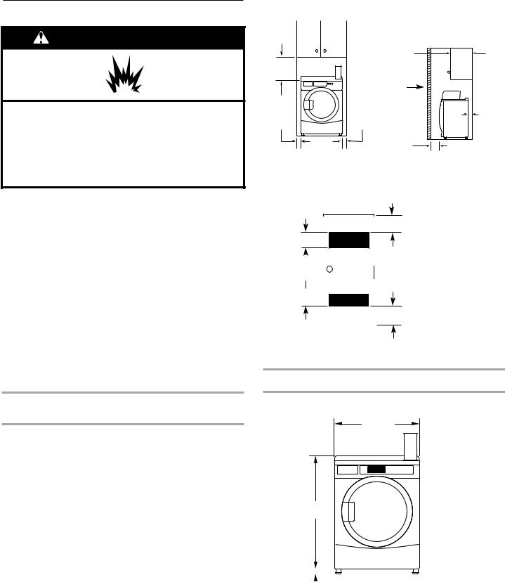
Recessed Area and Closet Installation Instructions
This dryer may be installed in a recessed area or closet. This dryer must not be installed behind a lockable door, a sliding door, or a door with a hinge on the opposite side to that of the dryer.
The installation spacingis in millimetersand is the minimumallowable. Additional spacing should be considered for ease of installation, servicing, and compliance with local codes and ordinances.
If installed in a closet with a door, the minimum unobstructed air opening in the top and bottom is required. Louvered doors with equivalent air openings are acceptable.
The dryer must be exhausted outdoors.
No other fuel-burning appliance may be installed in the same closet as the dryer.
Minimum Installation Clearances
|
|
356 mm |
381 mm |
|
(14") max |
|
|
|
(15") |
|
|
|
|
Closet |
|
|
door |
0 mm |
0 mm |
0 mm |
(0") |
(0") |
(0") |
|
|
25 mm (1") |
Recessed front view |
Closet side view |
Additional clearances for wall, door, and floor moldings may be required or if external exhaust elbow is used.
|
|
|
|
|
|
|
|
|
|
|
|
|
|
|
|
|
|
|
|
|
|
76 |
mm (3") |
||
|
|
|
|
|
|
|
|
|||||
310cm2* |
|
|
|
|
|
|
|
|
|
|
*Opening is the minimum |
|
|
|
|
|
|
|
|
|
|
|
|||
(48 in.2 ) |
|
|
|
|
|
|
|
|
|
|
for a closet door. Louvered |
|
|
|
|
|
|
|
|
|
|
|
doors with equivalent air |
||
|
|
|
|
|
|
|
||||||
|
|
|
|
|
|
|
|
|
|
|||
Front |
|
|
|
|
closet |
|
|
openings are acceptable. |
||||
|
|
|
|
|
|
|||||||
|
|
|
|
|
|
|
||||||
|
|
|
|
|
|
|||||||
view |
|
door |
|
|
|
|
|
|||||
|
|
|
|
|
|
|
|
|
|
|
|
|
155cm2* (24 in.2)
76 mm (3")
Product Dimensions 686 mm (27") dryer
686 mm
(27")
159 mm |
(61/4") |
ELECTRIC |
|
|
715 mm |
152 mm |
|
(281/8") |
|
89 mm |
|
(57/8") |
GAS |
(31/2") |
|
|
|
32 mm |
|
358 mm |
(11/4") |
|
(14") |
BACK VIEW
736 mm
(29") 695 mm (271/4")
203 mm (8")
921 mm (361/4")
|
|
|
|
|
|
|
|
|
|
|
|
|
|
|
|
|
|
|
|
|
|
25 |
|
mm |
|
SIDE VIEW |
||||||
|
|
|||||||||
|
|
|||||||||
(1") |
|
|
|
|
|
|
|
|||
Electrical Requirements – Gas Dryer
Important: Observe all governing codes and ordinances.
You will need an earthed electrical outlet located within 610 mm
965 mm (2 feet) of either side of the dryer.
(38")
|
|
|
|
|
|
|
|
|
|
|
|
|
|
|
|
|
|
|
|
|
|
|
|
25 |
|
mm |
|
|
|
FRONT VIEW |
|||||
|
|
|
|
||||||||
|
|
|
|
||||||||
(1") |
|
5 |
|||||||||

This dryer is supplied/fittedwithan electricity supplycordand plug. It should be connectedto electricitysupplysocketat the voltageshown on the rating plate.The minimumsupplyfusecapacity shouldbe 5A. The dryer must be positionedso thatthe plugis clearlyvisibleand accessible. This plug alsoprovidesthe function of an emergencystop control forthe user.If the fittedplug is notused, theelectricalconnection must be carriedout by a competentelectrician in accordancewithlocal or nationalcodes.
If the supply cord is damaged, it must be replaced with a specially terminated cord by an authorizedserviceagentor a similarlycompetent person in orderto avoid a hazard.
Do not use an adapter.
Do not use an extensioncord.
NOTE: In accordancewith theEuropeanEMCDirective(2004/108/EC), themaximumelectricity supplysystemimpedanceto whichthegas dryer should be connectedis declaredto be 0.054Ohm+ j0.034Ohm.
NOTE:Electrical safetystandards:The manufacturerhas chosencompliance withIEC/EN.60335 standardsas themostappropriateforthisproduct.
Using the universal cord included with this dryer:
The gas dryer is equipped with a universal cord with interchangeable plugs.
1.To use the universal cord, select the plug end that fits your electrical outlet, and plug it into the adapter on the supply cord.
2.Secure the plug end in place on the cord by aligning the 2 cover halves over the cord adapter and clipping them together.
Gas Supply Requirements
If codes permit and an additional earth bond wire is used, it is recommended that a qualified electrician determine that the earth bond path is adequate.
EARTHING INSTRUCTIONS
SAVE THESE INSTRUCTIONS
IMPORTANT: Observe all governing codes and ordinances.
Gas Supply
Before installation, check that the local gas distribution conditions, nature of gas and pressure, and the adjustment of the appliance are compatible. Burner information will be found on the model/serial rating plate in the door recess of the dryer. If this information does not agree with the type of gas available, see your dealer.
6
Natural Gas:
This dryer is factory adjusted for use with NATURAL GAS (G20), and no further adjustment should be required at installation.
L.P.Gas:
This dryer is also certified for use with L.P. (propane or butane) gases with appropriate conversion. No attempt shall be made to convert the appliance from the gas specified on the model/serial rating plate for use with a different gas without consulting the serving gas supplier.
Conversion must be done by a competent service technician. Gas conversion kit, part number W10233219, is available for purchase from your dealer. Full instructions are supplied with the kit.
Natural gas (France/Belgium):
This dryer is also certified for France/Belgium for use with G20/G25 gases (20 mbar/25 mbar) with appropriate conversion. No attempt should be made to convert this appliance from the gas specified on the gas rating label for use with a different gas without consulting the serving gas supplier.Gas conversion must be done by a qualified gas service technician. Conversion kit, part number (W10181947) is available for purchase from your dealer. Full instructions are supplied with the kit.
Supply line requirements:
Provide a rigid gas supply line to the dryer location. It should be minimum 12.5 mm (1/2") ID. When acceptable to the gas supplier and local codes, 10 mm (3/8") ID rigid supply line may be used for lengths under 6.1 m (20'). Pipe-joint compounds resistant to the action of L.P.gas must be used.
Gas connection to the dryer itself should be made by means of a flexible gas hose suitable for the appliance and gas category in accordance with national installation regulations. If in doubt, contact the gas supplier. It should be minimum 10 mm (3/8") ID.
A means of restraint should be used between the appliance and the wall to prevent straining of the rigid gas supply when the appliance is moved. An appropriate length of chain and a wall hook is recommended.
The dryer gas inlet connection is a 3/8" NPT thread. An adapter is supplied for conversion to standard ISO.228-1 thread (3/8" BSP).
Check for leaks by using an approved noncorrosive leakdetection solution. Bubbles will show a leak. Correct any leak found. A pressure measurement tapping is provided on the gas valve within the dryer, accessible after removal of the lower front panel.
The dryer must be disconnected from the gas supply piping system during any pressure testing of that system.
Venting Requirements
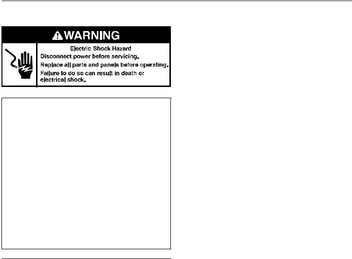
 WARNING
Fire Hazard
Use a heavy metal vent.
Do not use a plastic vent.
Do not use a metal foil vent.
Failure to follow these instructions can result in death or fire.
WARNING: To reduce the risk of fire, this dryer MUST BE EXHAUSTED OUTDOORS.
■Following these venting requirements will minimise ducting air noise.
■Gas dryers should only be installed in a room if the room meets the appropriate ventilation requirements specified in the national installation regulations. Make sure the room containing the dryer has an adequate air supply for gas combustion and drying operation. A window or equivalent means of ventilation must be opened in the room when the dryer is in use (an equivalent form of opening includes an
adjustable louver, hinged panel, or other means of ventilation that opens directly to outside air). Adequate ventilation has to be provided to avoid the backflow of gases into the room from other fuel-burning appliances, including open fires (i.e. available airflow into the room should match airflow out from the room).
■Thedesign of thefluesystemshouldbe suchthatanycondensate formedwhenoperatingthedryerfromcoldshalleitherbe retained and subsequentlyre-evaporatedor discharged.Followingthese instructions should adequatelymeet this requirement.
■The dryer vent must not be discharged into a flue which
is used for exhausting fumes from appliances burning gas or other fuels, chimney, wall, ceiling, or a concealed space of a building, or any other vent used for venting.
■Do not use an exhaust hood with a magnetic latch.
■Do not install flexible metal vent in enclosed walls, ceilings, or floors.
■102 mm (4") heavy metal vent and clamps must be used.
■Use clamps to seal all joints. Vent must not be connected or secured with screws or other fastening devices which extend into the interiorof the vent and catchlint. Do not use duct tape.
IMPORTANT: Observe all governing codes and ordinances. Use a heavy metal vent. Do not use plastic or metal foil vent. Rigid metal vent is recommended to avoid crushing and kinking.
Flexible metal vent must be fully extended and supported when the dryer is in its final position. Remove excess flexible metal vent to avoid sagging and kinking that will result in reduced airflow and poor performance.
An exhaust hood should cap the vent to keep rodents and insects from entering the building.
Exhaust hood must be at least 305 mm (12") from the ground or any object that may be in the path of the exhaust (such as flowers, rocks, or bushes).
If using an existing vent system, clean lint from the entire length of the system and make sure exhaust hood is not plugged with lint. Replace any plastic or metal foil vent with rigid metal or flexible metal vent.
7
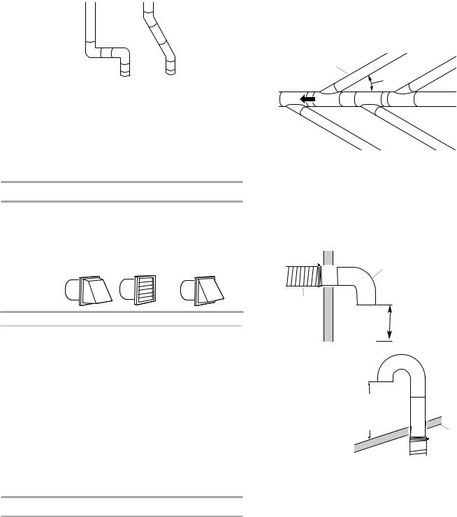
Plan installation to use the fewest number of elbows and turns.
A B
Exhaust Air Flow
A.Good
B.Better
Allow as much room as possible when using elbows or making turns. Bend vent gradually to avoid kinking.
Vent outlet is located at the center of the bottom dryer back.
The vent can be routed up, down, left, right, behind the dryer, or straight out the back of the dryer.
Vent System Length
Maximum length of vent system depends upon the type of vent used, number of elbows, and type of exhaust hood.
Maximum Vent Length
102 mm (4") Exhaust Hoods
|
Box |
Louvered |
64 mm (21⁄2") Angled |
Rigid Metal Vent |
|
|
|
No. of 90° turns |
Box Hood and Louvered Style |
Angled Hood Style |
|
0 |
39.6 m (130 ft.) |
39.3 m (129 ft.) |
|
1 |
38.1 m (125 ft.) |
36.3 m (119 ft.) |
|
2 |
35.1 m (115 ft.) |
33.2 m (109 ft.) |
|
3 |
32.3 m (106 ft.) |
30.5 m (100 ft.) |
|
4 |
98 m |
(98 ft.) |
28 m (92 ft.) |
If dryer is installed in a confined area, such as a bedroom, bathroom, or closet, provision must be made for enough air for combustion and ventilation. (Check governing codes and ordinances.) See “Recessed Area and Closet Installation Instructions” in the “Location requirements” section.
A 102 mm (4") outlet hood is preferred. However,a 64 mm (21⁄2") outlet exhaust hood may be used. A 64 mm (21⁄2") outlet creates greater back pressure than other hood types.
For permanent installation, a stationary vent system is required.
Multiple Dryer Venting
■A main vent can be used for venting a group of dryers. Main vent should be sized to remove 5663 l/min (200 CFM) of air per dryer. Large-capacity lint screens of proper design may be used in the main vent if checked and cleaned frequently. The room where the dryers are located should have make-up air equal to or greater than the airflow of all the dryers in the room.
■A back-draft damper kit is needed and is available from a commercial laundry distributor; it should be installed in the vent of each dryer to keep exhausted air from returning into the dryers and to keep the exhaust in balance within
the main vent. Unobstructed return air openings are required.
Each vent should enter the main vent at an angle pointing in the direction of the airflow. Vents entering from the opposite side should be staggered to reduce the exhausted air from interfering with the other vents.
The maximum angle of each vent entering the main vent should be no more than 30°.
A
 air !ow B
A.Individual dryer vent
B.Main vent
Keep air openings free of dry cleaning fluid fumes. Fumes create acids which, when drawn through the dryer heating units, can damage dryers and items being dried.
A clean-out cover should be located on the main vent for periodic cleaning of the vent system.
If an exhaust hood cannot be used:
B

 A D
A D
C
12" min.
(305 mm)
Min. 300 mm (12") clearance above any accumulation
of snow, ice, or debris such as leaves.
A.Exhaust hood or elbow
B.Wall
C.Main collector vent
D.Horizontal vent
E.180° sweep elbow
F.Vertical vent
G.Roof
 E
E
610 mm (24")
min. above
24" min.
(610 mm) F
highest point of building
G

 C
C
The outside end of the main vent should have a sweep elbow directed downward. If the main vent travels vertically through the roof, rather than through the wall, install a 180° sweep elbow on the end of the vent at least 610 mm (2 ft.) above the highest part of the building. The opening in wall or roof shall have a diameter 13 mm (1⁄2") larger than the vent diameter. The vent should be centered in the opening.
Do not install screening or cap over the end of the vent.
8
INSTALLATION INSTRUCTIONS – GAS DRYER
Install Leveling Legs |
Connect Vent |
|
NOTE: Slide dryer onto cardboard or hardboard before moving to avoid damaging floor covering.
1.Using two or more people, move dryer to desired installation location.
2.Take tape off front corners of dryer. Open dryer and remove the literature and parts packages. Wipe the interior of the drum thoroughly with a damp cloth.
3.Take two of the cardboard corners from the carton and place them on the floor in back of the dryer. Firmly grasp the body of the dryer and gently lay it on its back on the cardboard corners.
4.With one of the legs in hand, check the ridges for a diamond marking. That’s how far the leg is supposed to go into the hole.
5.Start to screw the leveling legs into the holes by hand. (Use a small amount of liquid detergent to lubricate the screw threads so it is easier to turn the legs.) Use a 1" (25 mm) wrench or socket wrench to finish turning the legs until you reach the diamond mark. Then fit a protective foot boot over each foot.
6.Now stand the dryer up.
7.Remove cardboard or hardboard from under dryer. Adjust the legs of the dryer up or down until the dryer is level.
Make Gas Connection
1.Remove red cap from gas pipe.
2.Connect gas supply to dryer. If the flexible gas hose has 3/8" BSP thread, use the supplied conversion thread adapter. Use pipe-joint compound resistant to the action of L.P.gas for gas connections.
If necessary for service, open the toe panel. Use a putty knife to press on the 2 toe panel locks located at the top of the toe panel. Pull downward on the toe panel to open. Toe panel is hinged at the bottom.
3.Open the shutoff valve in the gas supply line.
4.Test all connections by brushing on an approved noncorrosive leak-detection solution. Bubbles will show a leak. Correct any leaks found.
1.Using a 102 mm (4") clamp, connect vent to exhaust outlet in dryer. If connecting to existing vent, make sure the vent is clean. The dryer vent must fit over the dryer exhaust outlet and inside the exhaust hood. Make sure the vent is secured to exhaust hood with a 102 mm (4") clamp.
2.Move dryer into final position. Do not crush or kink vent. Make sure dryer is level.
3.Check to be sure there are no kinks in the flexible gas line.
Complete Installation
1.With dryer in final position, place level on top of the dryer, first side to side; then front to back. If the dryer is not level, adjust the legs of the dryer up or down until the dryer is level.
 WARNING
Electric Shock Hazard This dryer must be earthed.
Securely tighten all electrical connections.
Failure to do so can result in death, fire, or electric shock.
2.Plug into an earthed outlet.
3.Check dryer operation:
Press the selection button for a full cycle and let the dryer run for at least five minutes. Dryer will stop when time is used up.
NOTE: Dryer door must be closed for dryer to operate. When door is open, dryer stops, but timer continues to run. To restart dryer, close door and press a cycle button.
4.If the burner does not ignite and there is no heat inside the dryer, shut off dryer for five minutes. Check that all gas supply valves are in the “ON” position and that the electrical cord is plugged in. Repeat five-minute test.
9
MAINTENANCE INSTRUCTIONS
Maintenance instructions:
■Clean lint screen after each cycle.
■Removing accumulated lint (disconnect dryer from electricity and gas supplies before starting this task):
•From inside the dryer cabinet:
Lint should be removed every 2 years or more often, depending on dryer usage. Cleaning should be done by a qualified person.
•From the exhaust vent:
Lint should be removed every 2 years, or more often, depending on dryer usage.
If dryer does not operate, check the following:
■Electric supply is connected.
■Circuit breaker is not tripped or fuse is not blown.
■Door is closed. Listen closely to hear door switches activate.
■Selected cycle button has been pressed firmly and display shows cycle time.
■Check that gas supply shutoff valves are set in open position.
If you need assistance:
Contact your authorized Maytag Commercial Laundry distributor or visit: www.MaytagCommercialLaundry.com.When you call, you will need the dryer model number and serial number.
Both numbers can be found on the serial-rating plate located on your appliance.
TECHNICAL SPECIFICATIONS - GAS DRYER
220-240V~50Hz 1ph 3A max. IP24 Clothes capacity: 9.0 kg max. Sound pressure level, Lpa: 58 dBA (uncertainty, Kpa: +/–10 dBA) Total mass: 68 kg max.
Factory set for NATURAL GAS: Injector size: 2.2 mm Heat input gross: 5.9 kW
European Country: |
CH, CZ, CY, ES, GB, GR, HR, |
|
CY, CZ, DK, EE, FI, GR, HU, IT, |
|
IE, IT, PT, SI, SK, TR |
|
NO, RO, SE, SK, TR |
European Gas Category: |
II2H3+ |
|
II2H3B/P |
Gas Flow Rate: |
0.562703 m3/hr |
|
0.562703 m3/hr |
Supply Pressure (G20): |
20 mbar |
|
20 mbar |
|
|
|
|
Factory Adjusted Pressure: |
7.4 mbar |
|
7.4 mbar |
|
|
|
|
With LP Gas Conversion Kit: Injector size: 1.25 mm Heat input gross: 6.4 |
kW |
||
|
|
|
|
European Country: |
CH, CZ, CY, ES, GB, GR, HR, |
|
CY, CZ, DK, EE, FI, GR, HU, IT, |
|
IE, IT, PT, SI, SK, TR |
|
NO, RO, SE, SK, TR |
|
|
|
|
European Gas Category: |
II2H3+ |
|
II2H3B/P |
Butane Supply Pressure (G30): |
28-30 mbar |
|
30 mbar |
Adjusted Pressure: |
N/A |
|
N/A |
|
|
|
|
Propane Supply Pressure (G31): |
37 mbar |
|
30 mbar |
Adjusted Pressure: |
N/A |
|
N/A |
|
|
|
|
With France/Belgium NATURAL GAS conversion kit: Injector size: 1.65 mm |
Heat input gross: 5.9 kW |
||
European Country: |
FR, BE |
||
|
|
||
European Gas Category: |
I2E+ |
||
Supply Pressure (G20): |
20 mbar |
||
|
|
||
Supply Pressure (G25): |
25 mbar |
||
Adjusted Pressure: |
N/A |
|
|
|
|
|
|
NOTE: Conversion kit: From Natural Gas to LP Gas: Whirlpool Part No. W10233219.
Conversion kit: From Natural Gas to Natural Gas - France/Belgium: Whirlpool Part No. W10184947. Manufacturer: Whirlpool Corporation, 1300 Marion-Agosta Rd., Marion, OH 43302, USA.
EU representatives: Maytag UK Ltd., 2 St. Annes Blvd., Redhill, RH1 1AX, UK
& Bauknecht Hausgeräte GmbH, D-73614 Schorndorf, Germany
10
REVERSING THE DOOR SWING
Door swing can be changed from a right-side opening to left-side opening, if desired.
Place a towel or soft cloth on top of the dryer or work space to avoid damaging the surface.
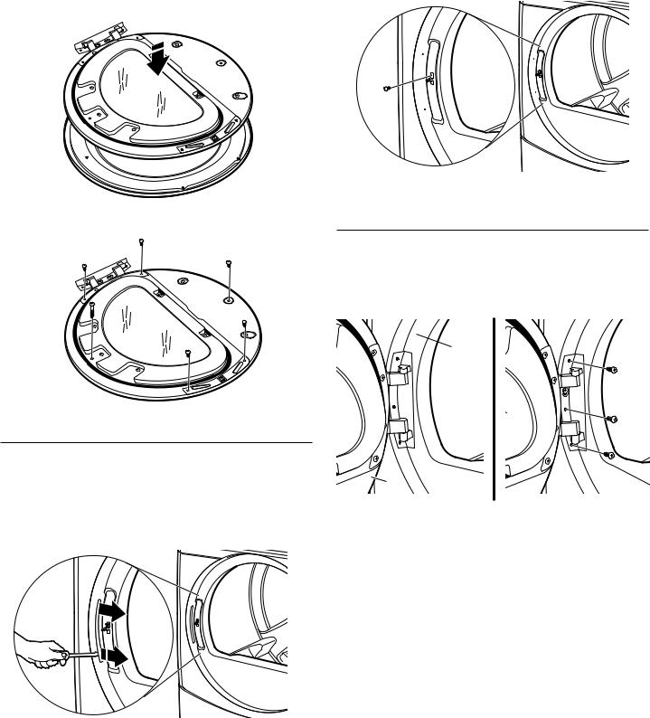
Remove the Door Assembly
1.Remove 3 of the 4 screws that hold the door hinge on the front panel of the dryer. Partially loosen the remaining screw with keyhole opening and lift the door off the screw.
 A.
A.
Loosen  screw
screw
with 
 keyhole
  opening
B.
A.Dryer front panel
B.Door assembly
2.Lay the door assembly on a previously prepared flat surface with the inside (inner door assembly) facing up.
3.Remove the 6 Phillips head screws to release the outer door assembly from the inner door assembly, as indicated below. See illustration. It is important that you remove only the 6 indicated screws.
5. Rotate outer door 180°.
Reverse Hinge
1.Use a small flat-blade screwdriver to remove 2 plug strips from the inner door. Slide the head of the screwdriver under the plugs, being certain not to scratch the inner door surface. Lift up.
2.Remove the 4 screws that attach to the inner door hinge and move the hinge to the other side. Reinstall the 4 screws.
4. Lift the inner door assembly off the outer door assembly.
Door hinge
3.Reinstall plug strips on opposite side of the inner door.
4.Check for fingerprints on the glass. Clean glass if necessary.
11
5.Place the inner door assembly inside the outer door assembly. To fit correctly,the inner door assembly edge fits completely inside the outer door assembly edge.
6.Reassemble the inner and outer door assemblies with the 6 screws.
Reverse the strike
1.Use a small flat-blade screwdriver to remove plug strip from the dryer door opening. Slide the head of the screwdriver under the plugs, being certain not to scratch the dryer surface. Lift the plastic strip from the dryer slowly to avoid distortion of the plug strip.
 B.
B.
 A.
A.
A.Plug strip
B.Door strike
2. Remove the strike using a Phillips screwdriver.
3. Insert strike on the opposite side.
Reinstall the door
1.Reattach door to dryer front panel with the 4 screws. Partially install the screw with keyhole opening first, and fit the keyhole opening in the hinge over the screw. Then install the remaining 3 screws and tighten all 4 screws.
 A.
A.
Install this 
 screw first
B.
A.Dryer front panel
B.Door assembly
2.Check for fingerprints on the glass. Clean glass if necessary.
3.Close door and check that it latches securely.
12
ELECTRONIC CONTROL SETUP
IMPORTANT
Electrostatic Discharge (ESD)
Sensitive Electronics
ESD is presenteverywhere.ESD may damageor weakenthe electronic controlassembly.The new controlassemblymay appear to work well after repair is finished,but failuremay occur at a later date due to ESD stress.
■Use an anti-static wrist strap.Connectwrist strap to green earth connection point or unpainted metal in the appliance.
-OR-
Touch your finger repeatedly to a green earth connection point or unpainted metal in the appliance.
■Before removing the part from its package,touch the anti-static bag to a green earth connectionpoint or unpainted metal in the appliance.
■Avoidtouchingelectronic parts or terminal contacts;handle electronic controlassembly by edges only.
■When repackaging failed electronic controlassemblyin anti-static bag, observe above instructions.
GENERAL USER INFORMATION
“out of order” showingin display
This condition indicates the dryer is inoperative.Diagnosticor failure code will follow the scrolling message.
‘0 Minutes’ showing in display
This conditionindicates the dryer cannot be operated. Coins dropped or debit inputs during this condition will be storedin escrow but cannot be used until normal operationis restored by opening and closing the door.If a door switch fails,it must be replaced beforenormaloperation can be restored.
Cold Start (initial first use)
Dryer is programmed at the factoryas follows:
■45 minutes dry time for PN models;5 minutesper coin for PD models.
■1.50 dry price (fixed cycle with top off - PD Models).
■0.00 dry price (fixed cycle - PN Models).
WarmStart (after power failure)
A few secondsafter power is restored,if a cycle was in progress at the time of the power failure, ‘RESELECT CYCLE’will flash
in the display. This is to indicate the need for a fabricsetting button to be pressed to restartdryer.
Pricing
After the door is openedand closedfollowingthe completionof a cycle,the displayindicatesthe cycleprice(unlessset for free operation). As coinsor debitinputsarrive,the displaywill change to lead the user through the initiationof a cycle.
Thereare four (4) typesof pricing:
Fixed ‘Vend’ Pricing
A dryer set up for ‘Fixed Cycle’ operation can only accept additional time accumulated by increments equal to the length of a complete dry cycle. A maximum of 99 minutes may be purchased; no additional credit is given when 99 minutes is in the display.
Accumulator Pricing
If the price is set to one coin 1, then accumulator mode is in effect. Cycle time can be purchased one coin at a time (PD models) up to the maximum time of 99 minutes.
Fixed Cycle With Top Off Pricing
A dryer set to offer ‘Top Off’ capability will allow time to be added to an existing dry cycle in increments equal to the number of minutes of dry time per coin (coin 1), up to 99 minutes, regardless of the cost required to start the dryer. No credit is given for coins or debit inputs entered when the control is displaying 99 minutes.
PN Models Set Up As PR: In Enhanced Debit Mode, the top off price can be set independently (see VALUE OF COIN 2), and the top off time is calculated according to the following equation:
top off price |
= |
top off time |
full cycle price |
full cycle length |
Hundredth increment offset is not applied to top off purchases.
PN Models
The factory has preset the cycle price to zero. When this happens, ‘SELECT CYCLE’ will appear rather than a cycle price. Any cycle started as a free cycle will automatically terminate when the door is opened.
Debit Card Ready
This dryer has a control that is debit card ready,but the dryer is not.
13
CONTROL SET-UP PROCEDURES
IMPORTANT: Read all instructionsbeforeoperating.
The fabric settingbuttonsalong with the digitaldisplayare used to set-up the dryer controls.
The display can contain4 numbers and/orlettersand a decimal point. These are used to indicatethe set-up codes and relatedcode values available for use in programming the dryer.
How to use the buttons to program the controls
1.The WHITES AND COLORSbuttonis used to adjustthe valuesassociatedwith set-upcodes.Pressingthe buttonwill increment the value by one (1). Rapid adjustmentis possible by holding the button down.
2.The PERM. PRESS button advancesthe displaythroughthe setup codes. Pressing the buttonwill advancethe displayto the next availableset-upcode. Holding the buttondown will automatically advance throughthe set-upcodes at a rate of one (1) per second.
3.The DELICATESbuttonis used to selector deselectoptions.
Start Operating Set-Up
■PD Models: Insert service door key, turn, and lift to remove access door.
■PN Models: Remove the AA1 jumper fromthe controlboard, see procedurebelow,or use the ServiceAccessCode below.Oncethe debit card readeris installed(accordingto the reader manufacturer’s instructions),the set-upmode can be enteredby inserting a manual set-up card (supplied by the readermanufacturer)into the cardslot. If manual set-up cardis not available,manualset-upmode cannot be entered.However,diagnosticmode can be enteredby removing connector AA1 on the circuitboard.
IMPORTANT: The console must not be openedunlesspower is first removed from the dryer.To access connectorAA1:
Unplug dryer or disconnectpower.
Open console, disconnectplug on AA1, close console.
Plug in dryer or reconnectpower.
■PN Models Equipped with ProgrammingSwitch:Insertaccess panel key and turn counter-clockwise.
■PN Models with Gen. 2 Debit Card Reader:Once a Gen. 2 debit card reader is installed (accordingto the readermanufacturer’s instructions), the set-up mode can only be enteredby inserting a manual set-up card (supplied by the readermanufacturer) into the card slot.
If manual set-up card is not available, only diagnosticmode can be entered.
■Alternate methodof entering Set-up Mode by enteringService Access Code: This code can be enteredto accessset-upmode without removing the consoleon dryers just removedfrom the carton, or not yet programmed. The ServiceAccessCode only functions on dryers set up for 0 vend price withoutany Special Pricing set-up,and the Coin/Debit Optionmust be set to “J._d”. If the dryer is not in failure mode, the door must be openedto proceed. Using only the threebottombuttons(numbered1, 2, and 3 from left to right):
1. Press 2 for longer than 2 secondsbut less than 10 seconds. 2. Press 1 & 3 simultaneously for 2 seconds.Displayshows S 3. 3. Press 1 & 2 simultaneously. Display shows S 4.
4. Press 2 & 3 simultaneously. Display shows S 5. 5. Press 2.
6. Waitat least 2 seconds, but not more than 15 seconds, then pressin succession:3, 2, 1, 3.
The dryer is now in the set-up mode.
Before proceeding, it is worth notingthat, despiteall the options available, an owner can simply chooseto uncratea new commercial dryer, hook it up, plug it in, and have a dryer that operates.NOTE: PD models require a payment systemor OPL kit to be installedprior to operation.
■PD dryersarepre-set at the factory for fixedcyclepricewithtop off.
■PN dryers are pre-set for fixed cycle operation,and they can be run withoutpayment.
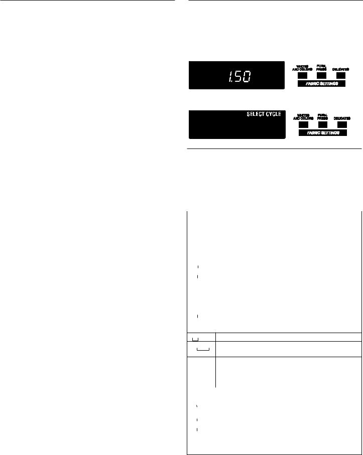
DISPLAY
After the dryer has been installed and plugged in, the display will show ‘0 minutes.’
Once the dryer has been plugged in and the dryer door opened and closed, the display will show the vend price. PN models are factorypresetfor freecycles;the displaywillflash‘SELECTCYCLE’.
PD Models
PRICE
PN Models
SET-UP CODES
FOR PN MODELS: The set-up codes are the same as for the PD models except where noted.
The set-up code is indicated by the one or two left hand characters. The set-up code value is indicated by the two or three right hand characters.
NOTE: The first line of each code indicates the factory default.
|
|
CODE |
EXPLANATION |
|||||
|
|
|
|
|
|
|
|
|
|
|
6 |
|
0 6 |
|
REGULAR CYCLE PRICE |
||
|
|
|
|
|
|
|
|
|
6 |
|
0 6 |
|
Represents the number of coins(coin 1); may adjust from 0-39 |
||||
|
|
|
|
|
|
|
|
(See b.xx set-up for VALUE OF COIN1). Advance from0-39 by |
|
|
|
|
|
|
|
|
pressing WHITESAND COLORS. Factory default of 6 x coin 1. |
6 |
|
0 0 |
|
PN MODELSONLY: Factorydefault of 6 00, or 0 coins. |
||||
|
|
|||||||
Press PERM. PRESS buttononce to advanceto next code.
|
70 |
5 |
|
|
REGULAR DRY TIME |
||
|
|
||||||
|
|
|
|
|
|
|
|
70 |
5 |
|
|
Represents the number of minutes per coin (coin 1). |
|||
|
|||||||
|
|
|
|
|
|
|
Factorydefaultof 5 minutes per coin. |
|
|
|
|
|
|
|
Example:6 coins x 5 minutes = 30 minutes. |
|
|
|
|
|
|
|
By pressing the WHITES ANDCOLORS button,value adjusts |
|
|
|
|
|
|
|
from1-99minutes. |
74 |
5 |
|
|
PN MODELS: Representsthe cycle lengthfor free cycles. |
|||
|
|
|
|
|
|
|
As example: ‘7 45’ = 45 minutes. |
Press PERM. PRESS buttononce to advanceto next code.
800 TYPE OF DRYER PRICING
800Fixed Cycle with Top Off. For detaileddescription,see General User Information.
8 |
|
FC |
|
Fixed Cycle. For detailed description,see GeneralUser |
|
|
|
|
Information. |
|
|
|
|
Use DELICATESbuttonto make thisselection. |
|
|
|
|
PN MODELS: Factory defaultof FC. |
Press PERM. PRESS buttononce to advanceto next code.
|
|
90 0 |
|
|
CYCLE COUNTER OPTION |
|||
|
|
|
|
|
|
|
|
This option is either SELECTED‘ON’ or NOT SELECTED‘OFF’. |
90 0 |
|
|
|
Not Selected ‘OFF’. |
||||
|
|
|||||||
|
|
|
|
|
|
|
|
|
|
|
90 C |
|
|
|
Selected ‘ON’ and not able to be deselected.Press DELICATES |
||
|
|
|
||||||
|
|
|
|
|
|
|
|
button 3 consecutive times to select ‘ON’. Once selected‘ON’ |
|
|
|
|
|
|
|
|
it cannot be deselected. |
Press PERM. PRESS buttononce to advanceto next code.
14
|
CODE |
EXPLANATION |
|
|
|
|
|
|
1.0 0 |
MONEY COUNTER OPTION |
|
|
|
|
This option is either SELECTED ‘ON’ or NOT SELECTED‘OFF’. |
|
|
|
|
1.0 0 Not Selected ‘OFF’.
1.0 C Selected ‘ON’.
|
|
|
|
Press DELICATES button 3 consecutive times to select ‘ON’ |
|
|
|
|
and 3 consecutivetimes to remove (Not Selected ‘OFF’.) |
|
|
|
|
Counter resets by going from ‘OFF’ to ‘ON’. |
1. |
|
C 0 |
|
Selected ‘ON’ and not able to be deselected. |
|
|
|||
|
|
|
|
To select ‘ON’ and not able to be deselected, first select ‘ON’, |
|
|
|
|
then within two seconds press DELICATES twice,WHITES AND |
|
|
|
|
COLORS once,and exit the set-upmode. |
Press PERM. PRESS button once to advance to next code.
|
2.0 0 |
|
SPECIAL PRICING OPTION |
|||||||
|
|
|
|
|
|
|
|
|
|
This option is either SELECTED ‘ON’ or NOT SELECTED‘OFF’. |
|
|
|
|
|
|
|
|
|
||
2. |
|
|
|
0 0 |
|
|
Not Selected ‘OFF’. |
|||
|
|
|
|
|
|
|
|
|
|
|
|
2. |
|
S P |
|
|
|
Selected ‘ON’. Press DELICATES button once for this |
|||
|
|
|
|
|
|
|
|
|
|
selection. |
If SPECIAL PRICING OPTIONis selected, there is access to codes ‘3.’ through ‘9.’
Press PERM. PRESS button once to advance to next code.
OPTIONS TO USE IF SPECIALPRICING IS SELECTED:
3. 0 6 SPECIAL CYCLE PRICE
3. 0 6 Represents the number of coins (coin 1); may adjust from 0-39. (See b.xx set-up for VALUE OF COIN 1). Advance from 0-39 by pressing WHITES AND COLORS.Factory default of 6 x coin 1.
3. 0 0 PN MODELS: Factory default of 0 coins.
Press PERM. PRESS buttononce to advance to next code.
4.0 5 SPECIAL DRY TIME
4.0 5 Represents the number of minutesper coin (coin 1).
Factory default of 5 minutes per coin. Example: 6 coins x 5 minutes = 30 minutes.
By pressing the WHITESAND COLORS button, the value can be adjusted from 1-99 minutes.
4. 4 5 PN MODELS:Representsthe cycle lengthfor free cycles. As example: ‘4 45’ = 45 minutes.
Press PERM. PRESS buttononce to advance to next code.
5.0 0 TIME-OF-DAY CLOCK, MINUTES
5. |
|
0 0 |
|
This is the TIME-OF-DAY CLOCK,minute setting; select 0-59 |
|
|
|
|
minutes by pressing WHITES AND COLORS button. |
Press PERM. PRESS buttononce to advance to next code.
6.00 TIME-OF-DAY CLOCK,HOURS
NOTE: Uses the 24 hr. clock.
6.0 0 This is the TIME-OF-DAY CLOCK,hour setting; select 0-23 hours by pressing WHITESAND COLORS button.
Press PERM. PRESS buttononce to advance to next code.
|
|
CODE |
EXPLANATION |
||||||
|
|
|
|
|
|
|
|
|
|
OPTIONS TO USE IF SPECIALPRICING IS SELECTED(continued): |
|||||||||
|
|
7. |
|
0 0 |
SPECIAL PRICE START HOUR |
||||
|
|
|
|
|
|
|
|
|
NOTE: Uses the 24 hr. clock. |
7. |
|
0 0 |
|
|
This is the start hour,0-23 hours.SelectSTARTHOUR |
||||
|
|
||||||||
|
|
|
|
|
|
|
|
|
by pressing WHITESAND COLORS button. |
Press PERM. PRESS button once to advance to next code.
|
|
8. |
|
0 0 |
SPECIAL PRICE STOP HOUR |
||||
|
|
||||||||
|
|
|
|
|
|
|
|
|
NOTE: Uses the 24 hr. clock. |
8. |
|
0 0 |
|
|
This is the stop hour; 0-23 hours.SelectSTOP HOUR |
||||
|
|
|
|
|
|
|
|
|
by pressing WHITESAND COLORS button. |
Press PERM. PRESS button once to advance to next code.
9.1 0 SPECIAL PRICE DAY
9. |
|
1 0 |
|
|
This represents the day of the week and whether special |
||||
|
|
|
|
|
pricing is selected for that day. A number followed by ‘0’ |
||||
|
|
|
|
|
indicates no selection that particularday (9.10).A number |
||||
|
|
|
|
|
followed by an ‘S’ indicates selected for that day (9.1S). |
||||
|
|
|
|
|
Days of week (1-7) can be chosenby pressing the WHITES |
||||
|
|
|
|
|
AND COLORS button. Press DELICATESbuttononce to |
||||
|
|
|
|
|
select special pricing for each day chosen. |
||||
|
|
|
|
|
When exiting setup code ‘9.’, the displaymust show current |
||||
|
|
|
|
|
day of week: |
|
|
|
|
|
|
|
|
|
DISPLAY |
DAY OF WEEK |
CODE (selected) |
|
|
|
|
|
|
|
10 |
Day 1 = Sunday |
1S |
||
|
|
|
|
|
20 |
Day 2 = Monday |
2S |
||
|
|
|
|
|
30 |
Day 3 = Tuesday |
3S |
||
|
|
|
|
|
40 |
Day 4 |
= Wednesday |
4S |
|
|
|
|
|
|
50 |
Day 5 |
= Thursday |
5S |
|
|
|
|
|
|
60 |
Day 6 |
= Friday |
6S |
|
|
|
|
|
|
70 |
Day 7 |
= Saturday |
7S |
|
Press PERM. PRESS button once to advance to next code.
A. 00 VAULT VIEWING OPTION
This option is either SELECTED‘ON’ or NOT SELECTED‘OFF’.
A. |
|
00 |
|
|
Not Selected ‘OFF’. |
||
|
|
||||||
|
|
|
|
|
|
|
|
A. |
|
SC |
|
|
Selected ‘ON’. Press DELICATESbuttononce for this |
||
|
|
||||||
|
|
|
|
|
|
|
selection. When selected,the money and/orcycle counts |
|
|
|
|
|
|
|
will be viewable (if countingis selected)when the coin box |
|
|
|
|
|
|
|
is removed. |
Press PERM. PRESS buttononce to advanceto next code.
|
|
6. |
|
|
05 |
VALUE OF COIN 1 |
|||
6. |
|
05 |
|
|
This represents the value of coin 1 in the quantityof 5% |
||||
|
|
|
|
|
|
|
|
|
increments of the larger coin value.5 x 5% = 25%. |
|
|
|
|
|
|
|
|
|
By pressing the WHITES AND COLORSbutton,there is the |
|
|
|
|
|
|
|
|
|
option of 1-199 for the quantityof 5% increments. |
|
|
|
|
|
|
|
|
|
With coin slide activation, this representsthe total vend price. |
Press PERM. PRESS buttononce to advanceto next code.
|
C.2 0 |
VALUE OF COIN 2 |
|||
|
|
|
|
|
|
|
C.2 0 |
|
|
This represents the value of coin 2 in the quantityof 5% |
|
|
|
|
|
|
increments of the larger coin value.20 x 5% = 100%. |
|
|
|
|
|
By pressing the WHITES AND COLORSbutton,there is the |
|
|
|
|
|
option of 1-199 for the quantityof 5% increments. |
|
C.0 5 |
|
|
PN MODELS: This represents the value of coin 2 in the |
|
|
|
||||
|
|
|
|
|
quantity of 5% incrementsof the largercoin value. Factory |
|
|
|
|
|
default = 5 x 5% of the largercoin value. |
|
|
|
|
|
PN MODELS USING ENHANCEDDEBIT:This represents the |
|
|
|
|
|
value of top off in quantityof 5% incrementsof the largercoin |
|
|
|
|
|
value. Factory default = 5 x 5% of the largercoin value. |
Press PERM. PRESS buttononce to advanceto next code.
15
|
|
CODE |
EXPLANATION |
||||||||
|
|
|
|
|
|
|
|
|
|
|
|
|
|
8. |
|
00 |
|
|
COIN SLIDE OPTION |
||||
|
|
||||||||||
|
|
|
|
|
|
|
|
|
|
|
This option is either SELECTED ‘ON’ or NOT SELECTED ‘OFF’. |
|
|
|
|
|
|
|
|
|
|
|
Replacement of metercase will be needed for coin slide mounting. |
8. |
|
00 |
|
|
|
|
Not Selected ‘OFF’. |
||||
|
|
|
|
|
|
|
|
|
|
|
|
|
|
8. |
|
CS |
|
|
Selected ‘ON’. |
||||
|
|
|
|
||||||||
|
|
|
|
|
|
|
|
|
|
|
NOTE: This option needs to be set to ‘00’ unless the |
|
|
|
|
|
|
|
|
|
|
|
metercase has been changed to accept a coin slide device. |
|
|
|
|
|
|
|
|
|
|
|
Press DELICATES button 3 consecutive times for this |
|
|
|
|
|
|
|
|
|
|
|
selection. When coin slide mode is selected, set ‘b.’ equal to |
|
|
|
|
|
|
|
|
|
|
|
value of slide in coins. Set ‘6 xx’ (REGULAR CYCLE PRICE) |
|
|
|
|
|
|
|
|
|
|
|
and ‘3.xx’ (SPECIAL CYCLE PRICE) to number of slide |
|
|
|
|
|
|
|
|
|
|
|
operations. 6 01 & 3.01 = 1 slide push. |
|
|
|
|
|
|
|
|
|
|
|
NOTE: If the installer sets up ‘CS’ on a coin drop model, |
|
|
|
|
|
|
|
|
|
|
|
it will not register coins. |
Press PERM. PRESS button once to advance to next code.
|
E. |
|
0 0 |
|
ADD COINS OPTION |
|||||||
|
|
|||||||||||
|
|
|
|
|
|
|
|
|
|
|
|
This option is either SELECTED ‘ON’ or NOT SELECTED ‘OFF’. |
|
|
|
|
|
|
|
|
|
|
|
|
This option causes the customer display to show the number |
|
|
|
|
|
|
|
|
|
|
|
|
of coins (coin 1) to enter, rather than the amount. |
|
E. |
|
|
0 0 |
|
|
Not Selected ‘OFF’. |
|||||
|
|
|
|
|
|
|
|
|
|
|
|
|
|
E. |
|
A C |
|
|
|
Selected ‘ON’. |
|||||
|
|
|
||||||||||
|
|
|
|
|
|
|
|
|
|
|
|
Press DELICATES button 3 consecutive times for this selection. |
|
|
|
|
|
|
|
|
|
|
|
|
PN MODELS: This option is not selectable. |
Press PERM. PRESS button once to advance to next code.
J.C 8 COIN/DEBIT OPTION
J.C 8 Both coin & debit selected. (NOT AVAILABLE)
J.C 8 Coins selected, debit disabled.
Press DELICATES button 3 consecutive times for this selection.
J. |
|
C 8 |
|
Debit Card selected, coin disabled. Default for PN models, |
|
|
|
|
and for PN operation, must be set as J._d. |
Press DELICATES button 3 consecutive times for this selection.
J. |
|
E 8 |
|
Enhanced Debit is self-selected when a Generation 2 card |
|
|
|
|
reader is installed in the dryer. The ‘Ed’ option cannot be |
|
|
|
|
manually selected or deselected. (NOT AVAILABLE) |
Press PERM. PRESS button once to advance to next code.
|
|
L. |
|
0 0 |
|
PRICE SUPPRESSION OPTION |
|||||||
|
|
|
|
|
|
|
|
|
|
|
|
|
This option is either SELECTED ‘ON’ OR NOT SELECTED ‘OFF’. |
|
|
|
|
|
|
|
|
|
|
|
|
|
This option causes the customer display to show ‘AVAILABLE’ |
|
|
|
|
|
|
|
|
|
|
|
|
|
or ‘ADD’ rather than the amount of money to add. (Used |
|
|
|
|
|
|
|
|
|
|
|
|
|
mainly in debit installations.) |
|
|
L. |
|
|
0 0 |
|
|
Not Selected ‘OFF’. |
|||||
|
|
L. |
|
PS |
|
|
Selected ‘ON’. Press DELICATES button once for this selection. |
||||||
Press PERM. PRESS button once to advance to next code.
|
8. |
|
C E |
CLEAR ESCROW OPTION |
|||||
|
|
||||||||
|
|
|
|
|
|
|
|
|
This option is either SELECTED ‘ON’ OR NOT SELECTED ‘OFF’. |
|
|
|
|
|
|
|
|
|
When selected, money held in escrow for 30 minutes without |
|
|
|
|
|
|
|
|
|
further escrow or cycle activity will be cleared. |
|
8. |
|
C E |
|
|
|
Selected ‘ON’. |
||
|
|
|
|||||||
8.00 |
|
Not Selected ‘OFF’. Press DELICATES button once to deselect |
|||||||
|
|
|
|
|
|
|
|
|
this option. |
|
|
|
|
|
|
|
|
|
|
Press PERM. PRESS button once to advance to next code.
|
|
0. |
|
0 0 |
|
HUNDREDTH INCREMENT OFFSET |
|||
0. |
|
0 0 |
|
|
This represents the hundredth increment price offset used |
||||
|
|
|
|
|
|
|
|
|
in Generation 2 (Enhanced Debit) PN models set up with card |
|
|
|
|
|
|
|
|
|
reader. Choose from 0-4 hundredths by pressing the WHITES |
|
|
|
|
|
|
|
|
|
AND COLORS button. (NOT AVAILABLE) |
Press PERM. PRESS button once to advance to next code.
If cycle counter (9 0C) is selected, the following is true:
1 00 Represents the number of cycles in HUNDREDS. 1 02 = 200
2 00 Represents the number of cycles in ONES. |
2 25 = 25 |
|
|
|
|
TOTAL CYCLES = 225
This is ‘VIEW ONLY’ and cannot be cleared.
Press the PERM. PRESS button once to advance to next code.
If money counter (1.0C or 1.C0) is selected, the following is true:
3 00 |
Currency amount in HUNDREDS. |
3 01 |
= 100.00 |
|
4 00 |
Currency amount in ONES. |
4 68 |
= |
68.00 |
5 00 |
Currency amount in HUNDREDTHS. |
5 75 |
= |
00.75 |
|
|
TOTAL = 168.75 |
||
END OF SET-UP PROCEDURES
EXIT FROM SET-UP MODE
■PD MODELS: Reinstall access door.
■PN MODELS where AA1 plug was removed:
1.Unplug dryer or disconnect power.
2.Open console, reinsert jumper into AA1, close console.
3.Plug in dryer or reconnect power.
■PN WITH PROGRAMMING SWITCH: Turn key clockwise and remove.
■If Service Access Code was used to enter set-up mode: From Set-up Code 8, press button #1 for 4 seconds, wait 2 minutes without touching any buttons (without diagnostic modes running), or power down the dryer, then reapply power.
EU - DECLARATION OF CONFORMITY
CE - DECLARATION DE CONFORMITE
BAUKNECHT HAUSGERÄTE GmbH, D-73614 Schorndorf representing (représentant): WHIRLPOOL EUROPE S.r.l I-21025 COMERIO
declare under our sole responsibility that the product déclarons sous notre propre responsabilité que le produit
dryer Maytag MDG22PD
(sèche-linge) :
Maytag MDG22PN
to which this declaration relates is in conformity with the following standard(s) or other normative document(s)
auquel se référe cette déclaration est conforme aux normes suivantes ou autres documents normatifs
EN 60335-1:2002+A1+A2+A11+A12+A13
EN 60335-2-11:2003+A1+A2
EN 12752-1:1999
EN 62233:2008
EN ISO 10472-1:2008
EN ISO 10472-4:2008
EN 55014-1:2006
EN 55014-2:1997+A1 :2001
EN 61000-3-11:2000
EN 61000-3-12:2005
following the provisions of Directive(s): suivant les prévisions des Directives :
2009/142/EC EUROPEAN GAS APPLIANCE DIRECTIVE 2006/95/EC LOW VOLTAGE DIRECTIVE (CEE Directive Basse Tension)
2004/108/EC ELECTROMAGNETIC COMPATIBILITY DIRECTIVE (CEE Directive Compatibilité Electro-magnétique)
2006/42/EC MACHINERY DIRECTIVE
|
represented by |
Schorndorf, 29.04.2010 |
Roberto Mottura |
Place and date: |
Director PDC, FC |
lieu et date : |
|
|
Name and signature of authorised person |
|
Nom et signature de la personne autorisée |
16

MAYTAG COMMERCIAL WASHER, DRYER, STACKED DRYER/ DRYER, COMMERCIAL STACK LAUNDRY, AND MULTI-LOAD COIN OPERATED COMMERCIAL WASHERS AND DRYERS WARRANTY
LIMITED WARRANTY ON PARTS
For the first five years from the date of purchase, when this commercial appliance is installed, maintained and operated according to the instructions attached to or furnished with the product, Maytag brand of Whirlpool Corporation (thereafter “Maytag”) will pay for factory specified parts or original equipment manufacturer parts to correct defects in materials or workmanship. Proof of original purchase date is required to obtain service under this warranty.
ITEMS MAYTAG WILL NOT PAY FOR
1.All other costs including labor, transportation, or custom duties.
2.Service calls to correct the installation of your commercial appliance, to instruct you how to use your commercial appliance, to replace or repair fuses, or to correct external wiring or plumbing.
3.Repairs when your commercial appliance is used for other than normal, commercial use.
4.Damage resulting from improper handling of product during delivery, theft, accident, alteration, misuse, abuse, fire, flood, acts of God, improper installation, installation not in accordance with local electrical or plumbing codes, or use of products not approved by Maytag.
5.Pickup and Delivery. This commercial appliance is designed to be repaired on location.
6.Repairs to parts or systems resulting from unauthorized modifications made to the commercial appliance.
7.The removal and reinstallation of your commercial appliance if it is installed in an inaccessible location or is not installed in accordance with published installation instructions.
8.Chemical damage is excluded from all warranty coverage.
9.Changes to the building, room, or location needed in order to make the commercial appliance operate correctly.
DISCLAIMER OF IMPLIED WARRANTIES; LIMITATIONS OF REMEDIES
CUSTOMER'S SOLE AND EXCLUSIVE REMEDY UNDER THIS LIMITED WARRANTY SHALL BE PRODUCT REPAIR AS PROVIDED HEREIN. IMPLIED WARRANTIES, INCLUDING WARRANTIES OF MERCHANTABILITY OR FITNESS FOR A PARTICULAR PURPOSE, ARE LIMITED TO ONE YEAR OR THE SHORTEST PERIOD ALLOWED BY LAW. WHIRLPOOL SHALL NOT BE LIABLE FOR INCIDENTAL OR CONSEQUENTIAL DAMAGES. SOME STATES AND PROVINCES DO NOT ALLOW THE EXCLUSION OR LIMITATION OF INCIDENTAL OR CONSEQUENTIAL DAMAGES, OR LIMITATIONS ON THE DURATION OF IMPLIED WARRANTIES OF MERCHANTABILITY OR FITNESS, SO THESE EXCLUSIONS OR LIMITATIONS MAY NOT APPLY TO YOU. THIS WARRANTY GIVES YOU SPECIFIC LEGAL RIGHTS AND YOU MAY ALSO HAVE OTHER RIGHTS, WHICH VARY FROM STATE TO STATE OR PROVINCE TO PROVINCE.
If you need service, please contact your authorized Maytag Commercial Laundry distributor. To locate your authorized Maytag Commercial Laundry distributor, or for web inquiries, visit www.MaytagCommercialLaundry.com.
9/07
For written correspondence:
Maytag Commercial Laundry Service Department
2000 M-63 North
Benton Harbor, Michigan 49085 USA
17
SECURITE DU SECHE-LINGE
Votre sécurité et celle des autres est très importante.
Nous donnons de nombreux messages de sécurité importants dans ce manuel et sur votre appareil ménager. Assurez-vous de toujours lire tous les messages de sécurité et de vous y conformer.
Voici le symbole d’alerte de sécurité.
Ce symbole d’alerte de sécurité vous signale les dangers potentiels de décès et de blessures graves à vous et à d’autres.
Tous les messages de sécurité suivront le symbole d’alerte de sécurité et le mot “DANGER” ou “AVERTISSEMENT”. Ces mots signifient :
AVERTISSEMENT
Risque possible de décès ou de blessure grave si vous ne suivez pas immédiatement les instructions.
Risque possible de décès ou de blessure grave si vous ne suivez pas les instructions.
Tous |
de sécurité vous diront quel est le danger potentiel et vous disent comment réduire le risque de blessure et |
ce qui |
se produire en cas de non-respect des instructions. |
POUR VOTRE SECURITE
1.Ne pas utiliser ou remiser d’essence ou autres matériaux inflammables dans cet appareil ménager ou à proximité de celui-ci.
2.Ne pas vaporiser d’aérosols à proximité de cet appareil ménager lorsqu’il est en fonctionnement.
3.Ne pas modifier cet appareil ménager.
AVERTISSEMENT : Pour votre sécurité, les renseignements dans ce manuel doivent être observés pour réduire au minimum les risques d’incendie ou d’explosion ou pour éviter des dommages au produit, des blessures ou un décès.
–Ne pas entreposer ou utiliser de l’essence ou d’autres vapeurs ou liquides inflammables à proximité de cet appareil ou de tout autre appareil électroménager.
–QUE FAIRE DANS LE CAS D’UNE ODEUR DE GAZ :
•Ne pas tenter d’allumer un appareil.
•Ne pas toucher à un commutateur électrique; ne pas utiliser le téléphone se trouvant sur les lieux.
•Évacuer tous les gens de la pièce, de l’édifice ou du quartier.
•Appeler immédiatement le fournisseur de gaz d’un téléphone voisin. Suivre ses instructions.
•À défaut de joindre votre fournisseur de gaz, appeler les pompiers.
–L’installation et l’entretien doivent être effectués par un installateur qualifié, une agence de service ou le fournisseur de gaz.
18
ELIMINATION DU SECHE-LINGE
EXIGENCES D’INSTALLATION
Outillage et pièces
Rassembler les outils et pièces nécessaires avant de commencer l’installation. Lire et respecter les instructions d’installation fournies avec chacun des outils de cette liste.
Outillage nécessaire
■Clé à tube de 200 mm (8") ou 250 mm (10")
■Clé à molette de 200 mm (8") ou 250 mm (10")
■Tournevis à lame plate
■Tournevis Phillips
■Clé à molette avec ouverture jusqu’à 25 mm (1") ou clé à douille hexagonale
■Niveau
■Clé à douille de 8 mm (5/16")
■Couteau utilitaire
■Brides de fixation
■Composé d’étanchéité des raccords filetés - résistant au propane
■Pistolet à calfeutrage et composé de calfeutrage (pour l’installation d’un nouveau circuit d’évacuation)
■Pince
■Couteau à mastic à lame rigide
Pièces fournies
Retirer le sac de pièces du tambour du sèche-linge. Vérifier la présence de toutes les pièces.
■ Patin (4) |
■ Modèles PN : Boîtier du |
|
■ Pied du sèche-linge (4) |
lecteur de carte, faisceau |
|
de câblage du lecteur de |
||
■ Modèles PD : Came pour |
||
carte, visserie |
||
le verrouillage de la porte |
||
|
||
de service |
|
REMARQUE : Le schéma de circuits de ce sèche-linge se trouve à l’intérieur du panneau inférieur avant, dans les fiches techniques.
19
Exigences d’emplacement
AVERTISSEMENT
Garder les matières et |
inflammables, telle |
que l'essence, loin de |
. |
Ne pas installer dans un garage. |
|
Le non-respect de ces instructions peut causer un décès, une explosion ou un incendie.
Pour l’installation d’un sèche-linge à gaz :
IMPORTANT : Respecter les dispositions de tous les codes et règlements en vigueur.
■Déterminer les exigences des codes : Certains codes limitent ou prohibent l’installation d’un sèche-linge dans un garage, un placard, ou une chambre à coucher. Consulter l’inspecteur local des bâtiments.
■Veiller à ce que les bords inférieurs de la caisse ainsi que l’arrière et les côtés inférieurs du sèche-linge soient exempts d’obstructions, afin de permettre le passage adéquat de l’air de combustion. Voir la section “Instructions d’installation dans un placard ou un encastrement”pour l’espace de dégagement minimal.
■Ne pas installer sur un tapis.
NOTE : Le sèche-linge ne doit pas être installé en un endroit où il serait exposé à de l’eau ou aux intempéries.
Instructions pour l’installation dans un placard ou un encastrement
Ce sèche-linge peut être installé dans un placard ou un encastrement. Ce sèche-linge ne doit pas être installé derrrière une porte verrouillable, coulissante, ou une porte avec charnière du côté opposé de l’emplacement de celle du sèche-linge.
Les distances de séparation sont exprimées en millimetre; il s’agit des distances minimales. Il est utile de prévoir des
distances de séparation supérieures pour faciliter l’installation et les travaux d’entretien, ou si ceci est exigé par les codes et règlements locaux.
Si la porte du placard est installée, on doit respecter la taille minimale des ouvertures d’entrée d’air au sommet et en bas. On peut utiliser une porte à jalousies offrant une surface de passage d’air équivalente.
Le circuit d’évacuation du sèche-linge doit être relié à l’extérieur.
Aucun autre appareil utilisant un combustible ne doit être installé dans le même placard.
Distances de séparation minimales
|
|
356 mm |
381 mm |
|
(14") max |
|
|
|
(15") |
|
|
|
|
Porte du |
|
|
placard |
0 mm |
0 mm |
0 mm |
(0") |
(0") |
(0") |
|
|
25 mm (1") |
Encastrement, vue avant |
Placard, vue latérale |
On doit prévoir un espacement additionnel pour tenir compte éventuellement des moulures du mur, de la porte et du plancher, ou si le circuit d’évacuation comporte un coude.
310cm2* (48 in.2 )
vue |
|
|
Porte du |
|
|||
avant |
placard |
||
|
|
|
|
155cm2* (24 in.2)
76 mm (3")
*Taille minimale de l’ouverture pour la porte du placard. On peut utiliser une porte à claire-voie offrant une surface de passage d’air équivalente.
76 mm (3")
Dimensions du produit – Sèche-linge de 686 mm (27")
686 mm
(27")
965 mm (38")
|
|
|
|
|
|
|
|
|
|
|
|
|
|
|
|
|
|
|
|
|
|
25 |
|
mm |
|
|
|
VUE AVANT |
|
|
||
|
|
|
|
|
|
|||||
|
|
|
|
|
|
|||||
(1") |
|
|
|
|
|
|
|
|||
20
 Loading...