


Maytag MDE-MDG21PRA, MLE-MLG23PRF, MDE-MDG21PNA, MDE-MDG21PDA, MLE-MLG23PRA User Manual
...This manual is to be used by qualified appliance technicians only. Maytag does not assume any responsibility for property damage or personal injury for improper service procedures done by an unqualified person.
Commercial
Single and
Stack Dryers
This Base Manual covers general information
Refer to individual Technical Sheet for information on specific models
This manual includes, but is not limited to the following:
MDE/MDG21PDA
MDE/MDG21PDD
MDE/MDG21PNA
MDE/MDG21PND
MDE/MDG21PRA
MLE/MLG23PDA
MLE/MLG23PDC
MLE/MLG23PRA
MLE/MLG23PDF
MLE/MLG23PRF
MLE/MLG23MNA
MLE/MLG23MNF
16022904 Revision 0 January 2004
Important Information
Important Notices for Servicers and Consumers
Maytag will not be responsible for personal injury or property damage from improper service procedures. Pride and workmanship go into every product to provide our customers with quality products. It is possible, however, that during its lifetime a product may require service. Products should be serviced only by a qualified service technician who is familiar with the safety procedures required in the repair and who is equipped with the proper tools, parts, testing instruments and the appropriate service information. IT IS THE TECHNICIANS RESPONSIBLITY TO REVIEW ALL
APPROPRIATE SERVICE INFORMATION BEFORE BEGINNING REPAIRS.
!WARNING
To avoid risk of severe personal injury or death, disconnect power before working/servicing on appliance to avoid electrical shock.
To locate an authorized servicer, please consult your telephone book or the distributor from whom you purchased this product. For further assistance:
Contact your local commercial product distributor or visit Web site www.maytagcommerciallaundry.com.
Recognize Safety Symbols, Words, and Labels
!DANGER
DANGER—Immediate hazards which WILL result in severe personal injury or death.
!WARNING
WARNING—Hazards or unsafe practices which COULD result in severe personal injury or death.
!CAUTION
CAUTION—Hazards or unsafe practices which COULD result in minor personal injury, product or property damage.
2 |
16022904 Rev. 0 |
©2004 Maytag Appliances Company |
Table of Contents |
|
Important Information ...................................................... |
2 |
Important Safety Information ........................................... |
4 |
General Information |
|
Model Identification ..................................................... |
7 |
Commercial Dryer Nomenclature ............................... |
7 |
Terminology/Definitions ............................................... |
8 |
How It Works .................................................................. |
9 |
Gas Valve Assembly ................................................... |
9 |
Test Equipment ............................................................ |
12 |
Troubleshooting Procedures ......................................... |
13 |
General Specifications ............................................... |
13 |
Wattage Specifications ............................................. |
13 |
Exhaust Ducts .......................................................... |
13 |
Electrical Troubleshooting ......................................... |
14 |
Drive Motor Check .................................................. |
14 |
Motor Test Cord ..................................................... |
15 |
Drive Motor Test ..................................................... |
15 |
Centrifugal Switch ..................................................... |
15 |
Air Shutter Adjustment .............................................. |
15 |
Manometer ................................................................ |
16 |
Mechanical Troubleshooting ...................................... |
17 |
Single Dryer Troubleshooting Guide .......................... |
18 |
Single Dryer Diagnostic Program ........................... |
26 |
Single Dryer Diagnostic Code ................................ |
27 |
Stack Dryer Troubleshooting Guide ........................... |
29 |
Stack Dryer Diagnostic Program ............................ |
34 |
Stack Dryer Diagnostic Code ................................. |
35 |
Disassembly Procedures |
|
Control Panel ............................................................ |
37 |
Microprocessor Board ............................................... |
37 |
Touch Pad Assembly ................................................ |
37 |
Transformer ............................................................... |
37 |
Meter Case ............................................................... |
37 |
Service Door Switch .................................................. |
38 |
Coin Vault Switch ...................................................... |
38 |
Coin Drop Acceptor ................................................... |
38 |
Coin Sensor .............................................................. |
38 |
Door Assembly .......................................................... |
38 |
Reversing Door Assembly ...................................... |
39 |
Door Disassembly.................................................. |
39 |
Front Panel ............................................................... |
39 |
Top Cover .................................................................. |
40 |
Door Switch ............................................................... |
40 |
Front Shroud Assembly Removal .............................. |
41 |
Outlet Duct, Shroud & Tumbler Front .................... |
41 |
Lint Filter ................................................................ |
42 |
Bearing & Pads ...................................................... |
42 |
Front Seal .............................................................. |
42 |
Belt ............................................................................ |
42 |
Baffles ....................................................................... |
43 |
Rear Shroud Assembly ............................................. |
43 |
Back Seal .............................................................. |
44 |
Roller & Bearing Assembly .................................... |
44 |
Thermostats .............................................................. |
45 |
Cycling Thermostat ................................................ |
45 |
Low-Cycling Thermostat ......................................... |
45 |
Thermal Fuse ......................................................... |
45 |
Hi-Limit Thermostat ................................................ |
45 |
Blower Assembly ...................................................... |
45 |
Blower Seal ............................................................ |
45 |
Blower Cover .......................................................... |
45 |
Blower .................................................................... |
46 |
Exhaust Duct Pipe ................................................. |
47 |
Drive Motor Assembly ............................................... |
47 |
Assembly Breakdown ............................................... |
47 |
Motor Switch .......................................................... |
47 |
Idler Arm Assembly ................................................ |
47 |
Gas Valve Assembly ................................................. |
48 |
Coil ......................................................................... |
48 |
Igniter ..................................................................... |
48 |
Gas Valve ............................................................... |
49 |
Combustion Cone .................................................. |
49 |
Inlet Duct ................................................................... |
49 |
Heater Enclosure ...................................................... |
49 |
Stack Dryer-Sloped Front .......................................... |
50 |
Service Panel & Switch ............................................. |
50 |
Access Cover ......................................................... |
50 |
Control Panel ......................................................... |
50 |
Microprocessor ...................................................... |
51 |
Coin Drop ............................................................... |
51 |
Front Panel ............................................................ |
52 |
Stack Dryer--Sloped Front (PR Model) ...................... |
53 |
Microprocessor ...................................................... |
53 |
Stack Dryer - MN Models .......................................... |
53 |
Front Panel ............................................................ |
53 |
Timer ...................................................................... |
54 |
Selector Switch ...................................................... |
54 |
Push-To-Start Switch ............................................. |
54 |
Machine-In-Use Light ............................................. |
54 |
Stack Dryer - Flat Front Models ................................ |
55 |
Front Panel ............................................................ |
55 |
Microprocessor ...................................................... |
55 |
Front Shroud Assembly ......................................... |
55 |
Motor & Heater Relays .......................................... |
56 |
Appendix A ............................................................... |
57 |
Programming ............................................................. |
58 |
Start Operating Set-up ........................................... |
58 |
General User Information ....................................... |
58 |
Set-Up codes ......................................................... |
60 |
Dryer Diagnostic Mode .......................................... |
66 |
Dryer Help Mode .................................................... |
66 |
©2004 Maytag Appliances Company |
16022904 Rev. 0 |
3 |
Important Safety Information
!WARNING
To reduce the risk of fire, electric shock, serious injury or death to persons when using your washer, follow these basic precautions:
•Read all instructions before using the dryer.
•Refer to the Grounding Instructions in the Installation Manual for the proper grounding of the washer.
•Do not dry articles that have been previously cleaned in, washed in, soaked in, or spotted with gasoline, dry-cleaning solvents, or other flammable or explosive substances as they give off vapors that could ignite or explode.
•Do not add gasoline, dry-cleaning solvents, or other flammable or explosive substances to the dryer. These substances give off vapors that could ignite or explode.
•Do not allow children to play on or in the dryer. Close supervision of children is necessary when the dryer is used near children. This is a safety rule for all appliances.
•Before the dryer is removed from service or discarded, remove the door to the drying compartment.
•Do not reach into the dryer if the drying tumbler is moving.
•Do not install or store the dryer where it will be exposed to water and/or weather.
•Do not tamper with the controls.
•Do not repair or replace any part of the dryer, or attempt any servicing unless specifically recommended in the User-Maintenance instructions or in published user-repair instructions that you understand and have the skills to carry out.
•To reduce the risk of an electric shock or fire, do not use an extension cord or an adapter to connect the dryer to the electrical power source.
•Use your dryer only for its intended purpose, drying clothes.
•Always disconnect the dryer from electrical supply before attempting any service. Disconnect the power cord by grasping the plug, not the cord.
•Install the dryer according to the Installation Instructions. All connections for venting, electrical power and grounding must comply with local codes and be made by licensed personnel when required. Do not do it yourself unless you know how!
•To reduce the risk of fire, clothes which have traces of any flammable substances such as vegetable oil, cooking oil, machine oil, flammable chemicals, thinner, etc. or anything containing wax or chemicals such as in mops and cleaning cloths, must not be put into the dryer. These flammable substances may cause the fabric to catch on fire by itself.
•Do not use fabric softeners or products to eliminate static unless recommended by the manufacturer of the fabric softener or product.
•Keep your dryer in good condition. Bumping or dropping the dryer can damage safety features. If this occurs, have your dryer checked by a qualified service person.
•Replace worn power cords and/or loose plugs.
•Be sure water connections have a shut-off valve and that fill hose connections are tight. Close the shut-off valves at the end of each wash day.
•Loading door must be closed any time the dryer is in operational fill, tumble, or spin. Do not attempt to bypass the loading door switch by permitting the dryer to operate with the loading door open.
•Always read and follow manufacturer’s instructions on packages of laundry and cleaning aids. Heed all warnings or precautions. To reduce the risk of poisoning or chemical burns, keep them out of the reach of children at all times (preferably in a locked cabinet).
•Always follow the fabric care instructions supplied by the garment manufacturer.
•Never operate the dryer with any guards and/or panels removed.
•Do not operate the dryer with missing or broken parts.
•Do not bypass any safety devices.
•Failure to install, maintain, and/or operate this dryer according to the manufacturer’s instructions may result in conditions which can produce bodily injury and/or property damage.
NOTE: The Warnings and Important Safety Instructions appearing in this manual are not meant to cover all possible conditions and situations that may occur. Common sense, caution and care must be exercised when installing, maintaining, or operating the dryer.
Always contact your dealer, distributor, service agent or the manufacturer about any problems or conditions you do not understand.
4 |
16022904 Rev. 0 |
©2004 Maytag Appliances Company |
Important Safety Information
!WARNING
To avoid personal injury or death from improper servicing, make sure you read and understand the descriptions and meaning of various safety symbols, words and labels used in this manual, before attempting any procedures described in the manual. Failure to understand and comply with safety information may result in severe personal injury or death.
General Information
This Service Manual describes the operation, troubleshooting, disassembly, and repair of Maytag® dryer. It is intended for use by authorized technicians who troubleshoot and repair these units.
NOTE: It is assumed that users of this manual are familiar with the use of tools and equipment used to troubleshoot and repair electrical, and mechanical systems; and understand the terminology used to describe and discuss them.
Related Publications
This is a base service manual, covering a range of similar models. It is intended to be used in conjunction with the Parts Manual and Technical Sheet covering the specific model being serviced.
Electrical Service Information
Proper Grounding and Polarization of 120 Volts Wall Outlets
For the safety of our customers and the Service Technician ALL appliances have a three–prong power cord and MUST be connected to a properly polarized AND grounded wall outlet.
This information was written for those who do not understand grounding and polarization of a wall outlet. A 120 volt wall outlet must always be wired as shown below.
|
Ground |
L1 |
Neutral |
|
|
Neutral |
|
side |
0 |
115±12 |
|
V.A.C. |
V.A.C. |
Round |
|
grounding |
115±12 |
V.A.C. |
|
prong |
|
About Ground Wires
In the event of an electrical short circuit, a ground wire reduces the risk of electric shock by providing an escape wire for the electric current.
Standard accepted color coding for ground wires is green or green with a yellow stripe.
Grounding wires and wires colored like grounding wires are NOT to be used as current carrying conductors.
!WARNING
To reduce the risk of fire, electric shock, serious injury or death, all wiring and grounding must conform with the latest edition of the National Electric Code, ANSI/ NFPA 70, or the Canadian Electrical Code, CSA C22.1, and such local regulations as might apply. It is the customer’s responsibility to have the wiring and fuses checked by a qualified electrician to make sure your home has adequate electrical power to operate the dryer.
!WARNING
To avoid risk of personal injury or death due to electrical shock:
•Observe all local codes and ordinances.
•Disconnect electrical power to unit before servicing.
•Ground appliance properly.
•Check with a qualified electrician if you are not sure this appliance is properly grounded.
•DO NOT ground to gas line.
•DO NOT ground to cold water pipe if pipe is interrupted by plastic, nonmetallic gaskets, or other insulating (nonconducting) materials.
•DO NOT modify plug on power cord. If plug does not fit electrical outlet, have proper outlet installed by qualified electrician.
•DO NOT have a fuse in the neutral or ground circuit. A fuse in the neutral or ground circuit could result in an electrical shock.
•DO NOT use an extension cord with this appliance.
•DO NOT use an adapter plug with this appliance.
•DO NOT pinch power cord.
©2004 Maytag Appliances Company |
1602904 Rev. 0 |
5 |
Important Safety Information
Explanation
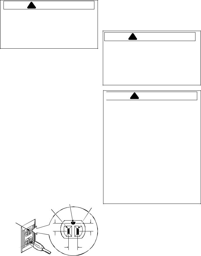
Polarization–This means that the larger slot must be neutral and the small slot must be at line voltage. Mispolarized–The outlet is incorrectly wired so that the larger slot is at line voltage and the smaller slot is neutral. Grounded–This means the round hole connection is connected to earth ground through a connection to the main power panel.
Ungrounded–The round hole connection is not complete to earth ground and/or the main power panel.
Grounding Instructions
!WARNING
•To avoid the risk of electrical shock or death, do not alter the plug.
•Do not remove grounding prong when installing grounded appliance in a home that does not have three wire grounding receptacle. Under no condition is grounding prong to be cut off or removed. It is the personal responsibility of the consumer to contact a qualified electrician and have properly grounded three prong wall receptacle installed in accordance with appropriate electrical codes.
•To avoid the risk of electrical shock or death, this equipment must be grounded.
This equipment MUST be grounded. In the event of an electrical short circuit, grounding reduces the risk of electric shock by providing an escape wire for the electric current. This unit is equipped with a cord having a grounding wire with a grounding plug. The plug must be plugged into an outlet that is properly installed and grounded.
Consult a qualified electrician or technician if grounding instructions are not completely understood, or if doubt exists as to whether the equipment is properly grounded. Do not use an extension cord. If the product power cord is too short, have a qualified electrician install a three-slot receptacle. This unit should be plugged into a separate 60 hertz circuit with the electrical rating as shown in the appropriate drawing. Models operate with a supply voltage of 120 Volts.
6 |
16022904 Rev. 0 |
©2004 Maytag Appliances Company |

General Information
Model Identification
Model and serial number is located on the back of the console and cabinet. It is important that you keep a record for future reference.
•For Maytag product call your distributor or visit the Web Site at www.maytagcommerciallaundry.com
When contacting provide product information located on rating plate. Record the following:
Model Number: |
___________________ |
Serial or S/N Number: |
___________________ |
Date of purchase: |
___________________ |
Distributor name and address: ___________________
Service
Keep a copy of sales receipt for future reference or in case warranty service is required. To locate an authorized distributor:
•For Maytag product call your distributor or visit the Web Site at www.maytagcommerciallaundry.com.
Service should be performed by qualified service technicians. We also recommend contacting an authorized distibutor, if service is required.
Parts and Accessories
Purchase replacement parts and accessories over the phone. To located an authorized distibutor:
•For Maytag product call your distributor or visit the Web Site at www.maytagcommerciallaundry.com.
Only factory approved replacement parts should be used.
Commercial Dryer Nomenclature
|
M |
|
DE |
|
|
21 |
|
PD |
|
A |
|
W |
|
W |
|
|
|||||||
|
|
|
|
|
|
|
|
|
|
|
|
|
|
|
|
|
|
|
|
|
|
|
|
|
|
|
|
|
|
|
|
|
|
|
|
|
|
|
|
|
|
|
|
|
|
|
|
|
|
|
|
|
|
|
|
|
|
|
|
|
|
|
|
|
|
|
|
|
|
|
|
|
|
|
|
|
|
|
|
|
|
|
|
|
|
|
|
|
|
|
|
|
|
|
|
|
|
|
|
|
|
|
|
|
|
|
|
|
|
|
|
|
|
|
|
|
Color Code |
||
|
Brand |
|
|
|
|
|
|
|
|
|
|
|
|
|
|
|
|
|
W - White |
||||
|
|
|
|
|
|
|
|
|
|
|
|
|
|
|
|
|
|
Q - Bisque |
|||||
M - Commercial Maytag |
|
|
|
|
|
|
|
|
|
|
|
|
|
|
|
||||||||
|
|
|
|
|
|
|
|
|
|
|
|
|
|
|
|
|
|
||||||
|
|
|
|
|
|
|
|
|
|
|
|
|
|
|
|
|
|
|
|||||
|
|
|
|
|
|
|
|
|
|
|
|
|
|
|
|
|
|
|
|||||
|
|
|
Product Type |
|
|
|
|
|
|
|
|
|
|
|
Voltage Code |
||||||||
|
DE - Electric Dryer |
|
|
|
|
|
|
|
|
|
|
|
W - 120V 60Hz |
||||||||||
|
DG - Gas Dryer |
|
|
|
|
|
|
|
|
|
|
|
X - 120V 60Hz (Canada) |
||||||||||
|
LE - Stack Electric Dryer |
|
|
|
|
|
|
|
|
Y - 240V 60Hz |
|||||||||||||
|
|
|
|
|
|
|
|||||||||||||||||
|
LG - Stack Gas Dryer |
|
|
|
|
|
|
|
|
Z - 240 60Hz |
|||||||||||||
|
|
|
|
|
|
|
|
|
|
|
|
|
|
|
|
|
|
|
|
|
|||
|
|
|
|
|
|
|
|
|
|
|
|
|
|
Marketing Code |
|
|
|
|
|||||
|
|
|
|
|
|
|
|
|
|
|
|
|
|
|
|
|
|
||||||
|
|
|
|
|
|
|
|
|
|
|
|
|
|
This identifies which |
|
|
|
|
|||||
|
|
|
|
|
|
|
|
|
|
|
|
|
|
|
|
|
|
||||||
|
|
|
|
Model Number |
|
|
|
version of production |
|
|
|
|
|||||||||||
|
|
|
21 - Single-Load Dryer |
|
|
|
the unit is |
|
|
|
|
|
|
|
|||||||||
|
|
|
23 - Stack Dryer/Dryer |
|
|
|
|
|
|
|
|
|
|
|
|
|
|||||||
|
|
|
|
|
|
|
|
|
|
|
|
|
|
|
|
|
|
|
|
|
|||
|
|
|
|
|
|
|
|
|
|
|
Control Type |
|
|
|
|
|
|
|
|||||
|
|
|
|
|
|
|
CS - Mechanical coin slide ready |
|
|
|
|
|
|
|
|||||||||
|
|
|
|
|
|
|
MN - Mechanical non-coin |
|
|
|
|
|
|
|
|
|
|
||||||
|
|
|
|
|
|
|
PD - Microprocessor with coin drop |
|
|
|
|
|
|
|
|||||||||
|
|
|
|
|
|
|
PN - Microprocessor non-coin |
|
|
|
|
|
|
|
|||||||||
|
|
|
|
|
|
|
PR - Microprocessor debit reader ready |
|
|
|
|
|
|
|
|||||||||
|
|
|
|
|
|
|
PS - Microprocessor coin slide ready |
|
|
|
|
|
|
|
|||||||||
©2004 Maytag Appliances Company |
1602904 Rev. 0 |
7 |

General Information
TERMINOLOGY/DEFINITIONS
TERM |
|
DEFINITIONS |
Amperage |
- |
The amount or the rate of flow of electrical current. |
Booster Coil |
- |
A coil used to assist the holding coil to raise the plunger in the gas valve allowing gas to |
flow |
|
into the second chamber of the valve. |
BTU |
- |
British Thermal Unit is the quantity of heat required to raise the temperature of one pound of |
|
|
water 1o F. |
Centrifugal |
- |
A switch device in a motor used to change the path of electricity from both start and run |
|
|
winding to run winding only. It also completes the circuit to the heat source when motor |
|
|
reaches speed. |
CFM |
- |
Air movement measured in cubic feet per minute. |
ClothesLifters |
- |
Devices attached to the inside of the tumbler used to lift and tumble the clothes during |
|
|
operation of the dryer. |
Coin Drop |
- |
A device which accepts and registers the number and denomination of coins used to start |
the |
|
dryer. |
Duct |
- |
A construction of aluminum or galvanized steel pipe used to convey moisture laden air from |
|
|
the dryer to the outside. |
Evaporation |
- |
The process of expelling moisture from garments by heat and/or air movement. |
Exhaust Hood - |
A damper placed at the terminating end of the ducting which prevents air from entering the |
|
|
|
duct when the dryer is not running. |
Glide Strip |
- |
A stationary bearing surface at the front on which the dryer tumbler turns. |
Holding Coil |
- |
A coil used to open the first valve in the gas valve assembly. It holds the valve open after |
|
|
the initial assistance from the booster coil. |
Igniter |
- |
A silicon carbide igniter located on the burner bracket near the main orifice. It can reach a |
|
|
temperature of 2200o F. in 30 seconds to ignite the gas (when allowed to flow through gas |
|
|
valve orifice). |
Light Emitting |
- |
A solid state indicator unit found as a single light and in a display Diode arrangement to |
form |
|
numbers and letters. |
Manometer |
- |
An instrument for measuring the pressure of gas or air. |
Microprocessor- |
The "brains" of the control board. A solid state "count and switch" processor device. |
|
OHM |
- |
A unit of measurement of resistance (opposition to the flow of current). |
Parallel Circuit - |
A circuit in which there is more than one current path. |
|
Radiant Sensor- |
Thermostat-like device which reacts to the brightness or radiant energy output of a heat |
|
|
|
source. |
Sensor Relay |
- |
A coil operated switch used to control dryer motors, heating element or gas valve on |
|
|
computer models. |
Relay |
- |
A coil operated switch used to control dryer motors, heating element or gas valve on |
|
|
Computer models. |
Resistor |
- |
A device used to limit the flow of current or reduce voltage. |
Run Winding |
- |
The main electromagnetic winding in a motor. |
Series |
- |
A circuit in which there is only one current path through all components. |
Start Winding |
- |
(Phase winding) An auxiliary winding used in an A.C. motor to assist the main winding in |
|
|
developing starting torque. |
Thermostat |
- |
A bimetal switch which reacts to temperature changes. |
Tumbler |
- |
Cylinder which contains and tumbles clothes. |
Voltage - |
Electric pressure that forces the current to flow in a circuit. |
|
Wattage |
- |
Wattage is a unit of measurement of the capability of electricity to do work. |
8 |
16022904 Rev. 0 |
©2004 Maytag Appliances Company |

General Information
HOW IT WORKS
The cycles are made up of three basic operations. White & Colors, Permanent Press and Delicates and Knits. These operation are sequenced by the controls (timer or microprocessor board) to provide a drying cycle for each of several different fabrics.
Incoming air is pulled over and around the exterior of the rotating tumbler. The air passing over the tumbler is preheated from the warm tumbler. This incoming air also passes over the inside of the cabinet lowering the cabinets temperature and minimizing the heat being dispelled into the laundry area.
The pre-conditioned air is pulled through the heat enclosure. As the air passes over the flame or heating element, it is heated causing the air to expand which increases its ability to absorb more moisture.
The heated air is pulled up the stack and through the grid in the tumbler back, through the tumbler, and to the lower area of the tumbler front. The tumbler is rotating in a clockwise direction lifting the
garments to the top of the tumbler. The garments fall free of the clothes lifters through the air stream. As this tumbling takes place, the garments keep turning over within the tumbler. Moisture is evaporated from the garments tumbling in the warm, dry air.
After passing through the garments, the air will contain moisture and lint. This air is pulled from the tumbler through a fine mesh filter located in the bottom of the door opening. The quantity of lint collected on the filter is dependent upon the size and type of load being dried.
From the filter, the air is pulled into the exhaust blower and forced out the exhaust system. The high speed blower is capable of moving up to 220 CFM of air. The volume of the tumbling chamber is approximately 6.0 cubic feet.
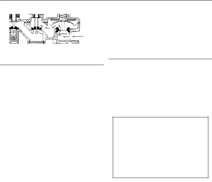
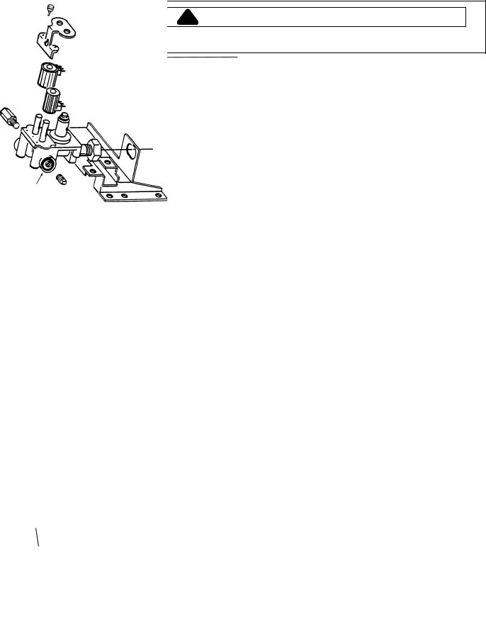
GAS VALVE ASSEMBLY
The gas controls utilize a hot surface ignition system. The three major components of the gas ignition system are: Igniter, Radiant Sensor and Gas Valve.
|
limit |
|
|
Thermostat |
|
Radiant |
Secondary |
|
Coil |
||
Sensor |
||
|
||
Igniter |
|
Gas Valve
Holding &
Booster Coil
Igniter - When the controls call for heat, line voltage is applied to the igniter. This causes the igniter to heat up and glow. It can reach a temperature of approximately 2200º F in approximately 30 seconds. Gas contacting the igniter at this temperature will ignite immediately.
Radiant Sensor - The radiant sensor operates much like a regular thermostat. It is mounted to the side of the combustion cone over an opening which exposes the sensor to the heat of the igniter and burner flame.
In its normal condition, the contacts in the radiant sensor are closed and the circuit is completed to the igniter. The igniter glow causes the radiant sensor contacts to open, thus breaking the circuit to the igniter.
Gas Valve - The gas valve is actually two gas valves, one in series with the other. The first valve is opened by a solenoid which has two separate coils built into one solenoid. This solenoid uses what is termed a split coil. The coils are referred to as the Holding Coil and the Booster Coil.
Both coils are needed to lift the armature and open the valve. The holding coil is strong enough to keep the valve open once the armature has been lifted.
The second of the two valves is operated by a one-coil solenoid. This is called a Secondary Coil.
©2004 Maytag Appliances Company |
1602904 Rev. 0 |
9 |
General Information
Booster |
Holding Coil |
|
Coil
Function of Gas Valve System
The sensor, igniter and gas valve are interrelated and function as ignition and heat source. At the start of the cycle, the radiant sensor contacts are closed, the igniter is at room temperature and the gas valve is closed, blocking the flow of gas. NOTE: On the wiring diagram, the radiant sensor contacts are wired in parallel with the secondary coil. This bypasses current around the secondary coil when the radiant sensor contacts are closed. Valve 2 cannot open with the radiant sensor contacts closed.
Step 1: Operation: Dryer Controls calling for heat: The red wire in the gas valve harness is normally the "hot" side of the line. Voltage is routed to the gas valve assembly through the cycling thermostat located on the blower cover and the hi-limit thermostat on the heater cone. The black wire to the gas valve is normally the neutral side of the line and is completed through the motor centrifugal switch.
Radiant Sensor Contact Closed
The holding coil, booster coil and igniter all receive line voltage. The holding coil and booster coil open Valve 1. Valve 2 is still closed, prohibiting gas flow to the burner. The igniter, operating at line voltage, begins to get very hot. (As the igniter gets hotter, the resistance of the igniter drops.) The igniter glow radiates heat to the radiant sensor.
Holding
Coil
|
|
Radiant |
|
|
|
Sensor |
|
To |
Booster |
|
|
Motor |
Igniter |
||
Coil |
|||
|
|
||
Valve 1 |
Valve 2 |
|
The booster coil and the igniter are wired in parallel.
Note: While these two components are in parallel with each other, they are wired in series with both the radiant sensor and secondary coil combination.
When the radiant sensor contacts are closed, full line voltage is available to the booster coil and to the igniter.
When the radiant sensor contacts open, current has to flow through the secondary coil on Valve 2 in order to get to the booster coil and igniter. A significant voltage drop develops across the secondary coil. While the parallel booster coil and igniter are still in the circuit, they become ineffective due to their low resistance and the resulting reduced voltage available to them.
The secondary coil on Valve 2 is bypassed because the radiant sensor contacts are closed. By not allowing voltage to the secondary coil, the second valve cannot open and prevents gas flow to burner.
Step 2: Radiant Sensor Contact Open:
The igniter is now hot and valve one (1) is open. The heat from the igniter causes the radiant sensor switch contacts to open.
With the radiant sensor contacts open, the secondary coil is no longer bypassed. The secondary coil is now in series with the parallel circuit combination of the booster coil and the igniter.
10 |
16022904 Rev. 0 |
©2004 Maytag Appliances Company |
General Information
Holding
Coil
|
|
Radiant |
|
|
Sensor |
To |
Booster |
|
Motor |
||
|
Coil |
Igniter |
|
|
|
|
Valve 1 |
Valve 2 |
Because of the relatively low resistance of the hot igniter, most of the line voltage is dropped across the secondary coil. The remaining voltage is dropped across the booster coil and igniter.
The secondary coil now opens the second valve releasing gas across the still extremely hot igniter. The gas ignites immediately and the burner flame is established.
Note: Since the igniter will cool, the tip is positioned in the burner flame which keeps it hot and resistance low.
The ignition cycle is now completed and the drying cycle begins.
Gas Conversions
The gas valve is set for use with natural gas when shipped from the factory. Because of differences in operating pressure and heat content of gases, the valve must be converted to use fuels other that natural gas.
Conversion kits are available to convert from natural to L.P. and back to natural. Check parts catalog for correct part number.
Safety Features
The design of the system provides for fail-safe operation in the event of power interruption, ignition failure, or flame failure as described below.
Power Interruptions
If the power to the burner assembly is cut off, either by opening the dryer door or by a power line failure, both valves in the gas valve assembly will close. Gas flow will cease.
When power is restored to the valve, the radiant sensor will start the process again. However, if the radiant sensor has not cooled and the contacts are still open, the secondary coil will receive full voltage and OPEN with no gas flowing through the secondary valve.
Since the secondary coil is in series with the booster coil, the reduced current flow through the booster coil is insufficient to create a strong enough magnetic field to help open the first coil valve. When the radiant sensor cools and closes its contacts, the sensor will shut the secondary coil again, providing a full current flow to the igniter and the booster coil, and system will go through a normal ignition sequence.
Ignition Failures
When the radiant sensor reacts to the heat from the igniter and the contacts open, the secondary coil energizes, opening the secondary valve. This allows gas to flow to the burner.
If no gas is present or the gas flow is not ignited, the radiant sensor will cool and the contacts will close, causing the secondary valve to close, thus allowing the igniter to reheat. The system will continue to cycle in this manner until normal ignition occurs or the dryer is turned OFF.
Flame Failure
If the burner flame should go out for any reason, the radiant sensor contacts will close in about 45 seconds and the gas system will go through a normal ignition sequence.
©2004 Maytag Appliances Company |
1602904 Rev. 0 |
11 |

General Information
!WARNING
To avoid risk of electrical shock, personal injury or death from improper servicing, make sure you understand the proper procedures and usage of tools listed, before attempting any procedures described in the manual. Failure to understand and comply with safety information may result in severe personal injury or death.
TEST EQUIPMENT
The equipment required to service Maytag products depends largely upon the condition you encounter. Locating a malfunction will often require the use of electrical testing equipment such as:
Analog Test Meter
can be used to check for open or closed circuits, measure resistance, AC and DC volts, and temperature.
Digital Test Meter
can be used to check for open or closed circuits, measure resistance, AC and DC volts, and temperature.
DESCRIPTION |
PART NUMBER |
|
Analog Test Meter |
20000005 |
|
Digital Test Meter |
20001001 |
|
Clamp-on Ammeter |
20000002 |
|
AC Voltage Sensor |
20000081 |
|
Air Test Meter |
20000029 |
|
Water Column |
038205 |
|
Manometer |
||
|
Clamp-On Ammeter can be used to detect shorts. Overloads on the circuit breaker or fuse can be traced to either the dryer or circuit breaker by checking the dryer current draw.
AC Voltage Sensor
can be used to alert you if AC voltage is present so proper safety precautions can be observed. The tip of the sensor will glow bright red if voltage is between 110-600 volts AC.
Air Test Meter
can be used to check back pressure in the exhaust duct. Vent restriction can cause back pressure and disrupt normal operations of the dryer.
Water Column Manometer can be used to check gas pressure being supplied to the dryer and the outlet tap pressure on the gas valve.
 8
8
 7
7
 6
6
 5
5
 4
4
 3
3
 2
2
 1
1
 0
0
 1
1
 2
2
 3
3
 4
4
 5
5

 6
6
 7
7
 8
8
12 |
16022904 Rev. 0 |
©2004 Maytag Appliances Company |
Troubleshooting Procedures
!WARNING
To avoid risk of electrical shock, personal injury or death, disconnect power to unit before servicing, unless testing requires power.
General Specifications
Capacity |
6.0 Cubic Feet |
One washer load is a full dryer load |
|
|
|
Motor |
Thermo-protected against overload auto-reset |
1/4 HP, 120 Volt, 60 Hz |
|
|
|
Air Flow |
Cubic feet per minute exhausted from dryer |
220 CFM |
Tumbler |
Revolution per minute |
52 RPM |
|
|
|
Rotation |
Drum Turning, when viewed from the front |
Clockwise |
|
|
|
Heat Source |
• Electric |
• 240 volt, 5600 watts, 30 amp fuse |
|
• Gas |
• Single port burner 24,000 BTU/hr. |
|
|
direct ignition, automatic shut-off |
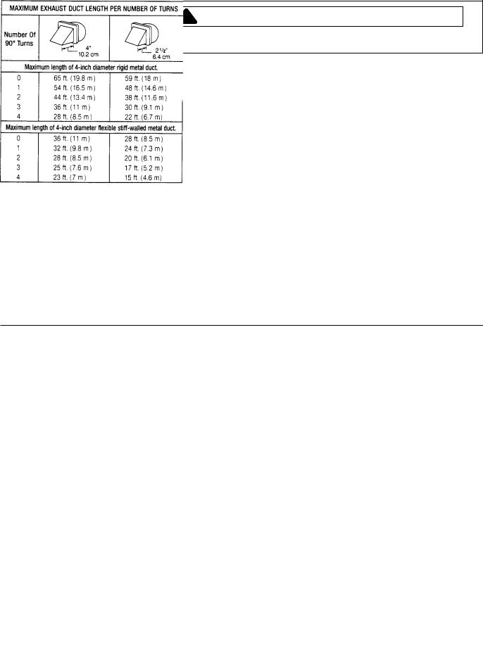
Exhaust |
Venting size |
4"(10.2 cm) duct, rigid aluminum |
|
|
duct work. (See installation instruc- |
|
|
tions that are provided with the |
|
|
product for additional information.) |
|
|
|
Makeup Air |
Free opening |
Requires 30 sq. in. per dryer pocket |
|
|
|
Static Pressure |
Single unit exhausting, 4" round rigid |
Should not exceed 0.92" or less |
|
|
than 0 water column inches |
|
|
|
Wattage Specifications
|
DESCRIPTION |
WATTS |
|
|
|
|
|
|
|
|
Gas Dryer |
350 Maximum without igniter |
|
|
|
|
|
|
|
|
Electric |
5900 |
(240V)/5600 208V) |
|
|
|
|
|
|
|
Heating Element |
5600 |
(240V)/5100 (208V) |
|
|
|
|
|
|
|
Igniter (NOTE: Ohm room temperature 180-400) |
600 |
|
|
|
|
|
|
|
|
|
|
|
|
Exhaust Ducts
©2004 Maytag Appliances Company |
16022904 Rev. 0 |
13 |
Troubleshooting Procedures
!WARNING
To avoid risk of electrical shock, personal injury or death, disconnect power to unit before servicing, unless testing requires power.
ELECTRICAL TROUBLESHOOTING
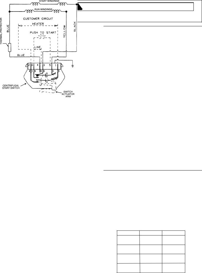
The malfunction of an electrical circuit cannot easily be diagnosed unless you first understand how it functions when operating normally. The electrical schematic and wiring diagram includes a cycle sequence chart keyed to the contacts in the timer, relay and/or control switches.
!CAUTION
Resistance or continuity testing is done with the product disconnected from power. Failure to do so can result in damage to your meter.
For the most part, we will only be concerned with continuity. Is there a path or not? References are made between a “closed” (Continuity) reading and an “open (No continuity) reading. One note, when you get and “open” reading, try a higher resistance range (setting). A very high resistance appears as an “open” on the lower ranges. For best accuracy always “rezero” meter when changing ranges and/or the physical position of the meter.
Continuity testing, as related to an electrical component, is the check of a part for an “open” or closed” circuit.
Continuity test of load devices will show varying levels of resistance from very low for some transformer and motor windings to very high for some timer motors and components on control boards. Usually it is more important to know if there is a path for current flow through a device (continuity ) that to know the exact resistance (ohms) of the device.
Continuity tests of switches will show virtually no resistance across a closed contacts. Resistance, even low value indicate burned or dirty contacts in a switch.
When checking components or circuit paths for continuity, external wiring should be disconnected to eliminate false readings through external paths. Isolate what you want to test.
Drive Motor Check
The motor features a leadless motor connection, comprised of a quick connector wire harness which connects directly to the motor. The connector has two locking tabs securing the connector to the motor switch. Press on both locking tabs to release the connector from the motor switch.
Press Here to Release
Connector
Motor Switch
Electrical components fall into two general categories.
1.Loads - Devices that use or consume electricity. Examples would include drive motor, timer and solenoids coils.
2.Switches - Devices that control the supply of electricity to the load or loads in a circuit. Examples include lid switches, timer contacts selector switch and relay contacts.
With the wire harness connector removed, press inward on the brown actuator disc in the motor. The start and run winding can now be checked for proper ohms. Place the leads from an ohm meter on the proper terminals as listed in the following chart.
Using an ohm meter, you can also check the wiring harness for continuity from the timer to the motor.
14 |
16022904 Rev. 0 |
©2004 Maytag Appliances Company |
Troubleshooting Procedures
!WARNING
To avoid risk of electrical shock, personal injury or death, disconnect power to unit before servicing, unless testing requires power.
Winding |
Terminal |
Terminal |
Ohms |
|
|
|
|
Start |
3 |
4 |
3.00 |
|
|
|
|
Run |
5 |
4 |
2.25 |
|
|
|
|
Motor Test Cord
A motor test cord may be used to electrically check operation of the various electrical components without removing them from the unit. Testing in this manner determines whether or not the part will function independently of other electrical components. In order to make an accurate test, proper connection of the motor test cord is important.
Drive Motor Test
The motor may be checked in the dryer or removed and checked.
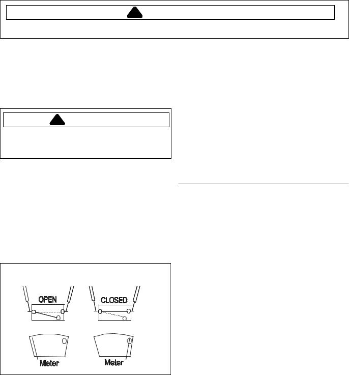
Centrifugal Switch
Checking heater/gas valve and motor:
1.Disconnect the wire harness from the motor.
2.Place ohm meter leads to terminals 1 and 2.
3.With your thumbs, depress the BROWN disc located behind the motor switch on the motor shaft. The BROWN disc actuates the lever of the motor switch when the motor is at rest. At optimum motor speed, the disc moves away from the switch lever. When the disc is pressed in toward the windings, the actuator arm of the centrifugal switch will be relaxed. This allows the contacts to close, completing the heater circuit. If no continuity is found when the disc is depressed, change the centrifugal switch.
Motor
Switch
"Brown" Disc
Switch Actuator
Side View of Motor
Air Shutter Adjustment
The air shutter has been stamped "LP" and "N" (for Natural). Loosen the screw holding the shutter, rotate the shutter until the end of the slot (labeled for the gas to be used) contacts the screw. Tighten the screw to lock the shutter in place.
Two test leads are required to check operation of the drive motor. To check the motor for operation, hook the test cord to terminals 4 and 5.
©2004 Maytag Appliances Company |
16022904 Rev. 0 |
Gas Type |
Natural |
LP |
BTU Per |
1050 |
2050 |
Cu. Ft |
|
|
Pressure |
3.5 |
11 |
Switch |
|
|
Specific |
0.65 |
1.53 |
Gravity |
|
|
Orifice |
41 |
53 |
Size |
|
|
15
Troubleshooting Procedures
!WARNING
To avoid risk of electrical shock, personal injury or death, disconnect power to unit before servicing, unless testing requires power.
Manometers
Insufficient gas flow can cause problems. Therefore, checking the gas pressure at the time service calls are performed may prevent a return call.
Gas pressure can be checked with an instrument called a "manometer." This device can detect a "low" LP tank, restricted gas flow, bad gas valve, a malfunctioning pressure regulator, too many gas appliances operating off of a small supply line, or an improperly converted appliance from Natural to LP gas.
Other types of manometers exist; however, the type of manometer we will discuss in this manual is a "U" shaped tube in which water is added. Both ends are open so the water can equalize and seek its own level, which will be the same in both arms of the "U" shaped tube.
A flexible rubber hose is connected to the lower, open end of the manometer and to the gas source. Gas pressure is exerted on one of the water columns, pushing it down.
The water level then rises in the other column. The difference in water levels equals the measure of gas pressure.
The water column (W.C.) for a Maytag dryer is 3.5" W.C. for Natural gas and 11" W.C. for LP.
How to Use:
1.Disconnect power supply to unit.
2.Remove front panel.
3.Shut off the gas to the dryer.
4.Install a 1/4" tapered fitting at the gas valve pressure tap. Use thread seal tape or compound on fitting.
5.Fill the manometer tube with water until each side equalizes at "0" water column.
6.Push the end of the manometer hose onto the 1/4" fitting located on the gas valve.
7.Connect hose to one end of the manometer.
8.Turn on the gas and reconnect dryer to power. Run the dryer in a heat cycle. Read the manometer with the burner ON, (check for gas leaks).
9.When the gas is on, the amount of water column present is equal to the total amount of deflection shown in the manometer.
Note: Once the test is completed, make sure the tapered fitting is removed from the gas valve and the plug is repositioned into the gas valve and resealed with pipe seal. Check for gas leaks again with a soap or bubble solution. NEVER
USE OPEN FLAME TO CHECK FOR GAS LEAKS.
Note: IF HIGH WATER COLUMN PRESSURE IS DETECTED; the gas flame can damage the flame spreader on the burner. (this can be cuased by the wrong orfice, improper air mixture or high gas pressure. If pressure is as high as suspected, contact the local gas utilities company to check the outside regulator.)
Gas Valve
Orfice
Valve
Pressure Tap
16 |
16022904 Rev. 0 |
©2004 Maytag Appliances Company |
Troubleshooting Procedures
!WARNING
To avoid risk of electrical shock, personal injury or death, disconnect power to unit before servicing, unless testing requires power.
Mechanical Troubleshooting
Will Not Run
If dryer will not start or run, check the following:
•All wires are hooked up to their corresponding terminals.
•Dryer is plugged in.
•Blown fuse or circuit breaker.
•Door switch functional...door closed.
•Push-to-start switch functional.
•Timer functional...set in a cycle.
•Drive motor functional.
•Blown thermal fuse.
If drive motor runs, but the tumbler will not turn, check the following:
•Belt off or broken/damaged.
•Idler tension spring too weak or stretched.
•Idler pulley jammed or stuck.
If dryer runs a few minutes and then stops - motor overload protector opens, check the following:
•Lint buildup around drive motor.
•Low voltage present.
•Blower impeller blocked in blower housing.
•Drive motor - start switch contacts stuck closed.
If dryer blows fuses or trips circuit breaker, check the following:
Electric Models
•The amperage readings are at 240 volts. One line will be 24 amps and other line will be 21 amps. The neutral line will be at 4 amps. If the above amperages are present, then the house wiring, fuse box or circuit breaker should be suspected.
•Shorted heating element to housing.
•Incorrect wiring or a wire shorting to ground.
•Drive motor winding shorting to ground.
Gas Models
•During ignition, the dryer will draw 7 amps. With the burner ON, the dryer will draw 4.5 amps. If the dryer is drawing amperages below this, then the house wiring, fuse box or circuit breaker are suspected to be at fault.
•Igniter harness loose and shorted to base.
•Incorrect wiring or wire shorted to ground.
•Drive motor winding shorting to ground.
Will Not Shut-Off
On time dry settings, check the following:
•Timer motor receiving proper voltage.
•Check timer motor connections.
•Timer functional.
Will Not Dry
If dryer will not heat (motor runs), check the following:
•Restricted exhaust caused by plastic or thin foil flexible duct.
•Open heating element.
•Hi-Limit thermostat trips too soon or is open.
•Cycling thermostat trips too soon or is open.
•Temperature selector switch mis-wired or contacts open.
•Timer functional.
•Cycle selector switch mis-wired or contacts open.
•Drive motor centrifugal start switch not allowing voltage to gas valve or heating element.
If improper drying/clothes wrinkled/rough texture/taking too long to dry, check the following:
•Restricted exhaust caused by plastic or thin foil flexible duct.
•Lint filter is not clean.
•Restriction in exhaust.
•Outside exhaust hood damper door stuck closed.
•Exhaust too long, too many elbows, flex ductwork installed.
•Poor makeup air available for the dryer.
•Incorrect tumbler speed. Tumbler belt slipping.
•Blower impeller bound; check for foreign material in blower area.
•Customer overloading dryer.
•Check clothing labels for fabric content and cycle selected.
•Gas valve coil opens - weak point in coil opens when stressed under heated conditions.
•Clothes too wet due to insufficient spinout by washer.
Noisy and/Or Vibration
•Thumping. Check for loose tumbler baffle, rear tumbler roller(s) worn or misaligned, out-of-round tumbler or high weld seam on tumbler.
•Ticking. Check for loose wire harness or object caught in blower wheel area.
•Scraping. Check for front or rear bulkhead felt seal out of position or worn tumbler front Rulon™ bearings.
•Popping or squealing sound. Check for a sticky or frayed belt.
©2004 Maytag Appliances Company |
16022904 Rev. 0 |
17 |
Troubleshooting Procedures
!WARNING
To avoid risk of electrical shock, personal injury or death, disconnect power to unit before servicing, unless testing requires power.
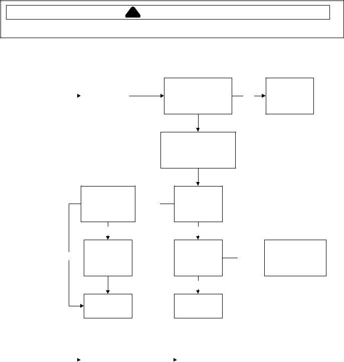
Single Dryer Troubleshooting Guide
Display Is |
|
|
Make sure dryer is |
|
|
plugged in to live |
|
|
|||
Blank |
power source |
||
|
|
|
|
Is the exhaust tube nipple on the side of the display damaged?
No
Initiates the Yes manual reset
sequence
Enter service mode using service switch does display contain a diagnostic code?
Unplug dryer and check wiring and termination between transformer, service switch, and control board.
Plug in dryer, open service door is
 Yes there 26 VDC across the service
door. switch?
No
Does 115 VAC appear across the primary of the transformer?
Yes
See diagnostic code guide.
Replace the transformer, inspect
Yes  control board for burned components and replace
it if damaged
No
If problem still exists replace the control board
Check wiring to transformer and power at outlet.
Abnormal |
Unplug the machine |
|
|
|
||
then plug it back in. If |
|
|
If problem still exists, |
|||
|
|
|
problem still exist, |
|
|
|
Display |
|
|
replace the control board. |
|||
initiate the manual reset |
|
|
||||
Function |
|
|
|
|||
sequence. |
|
|
|
|||
|
|
|
|
|
|
|
|
|
|
|
|
|
|
18 |
16022904 Rev. 0 |
©2004 Maytag Appliances Company |
Troubleshooting Procedures
!WARNING
To avoid risk of electrical shock, personal injury or death, disconnect power to unit before servicing, unless testing requires power.
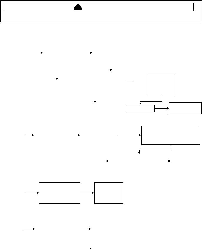
Single Dryer Troubleshooting Guide
Dryer |
|
|
|
|
|
|
|
|
|
|
|
|
|
|
|
|
|
|
|
|
|
|
|
|
|||
Stopped |
|
|
Open |
|
|
|
|
|
|
|
Unplug dryer and open |
||||||||||||||||
with Zero |
|
|
|
|
|
|
|
|
|
||||||||||||||||||
|
|
corresponding |
|
|
|
|
|
|
|
doors. Check continuity |
|||||||||||||||||
|
|
|
|
|
No |
|
|
||||||||||||||||||||
|
|
|
|
|
|
|
|
|
|
|
|||||||||||||||||
Minutes |
|
|
dryer door. Did |
|
|
|
|
|
|
of problem door switch |
|||||||||||||||||
|
|
|
|
|
|
|
|
|
|
||||||||||||||||||
Remaining |
|
|
display change? |
|
|
|
|
|
|
|
and replace it if shorted. |
||||||||||||||||
In The |
|
|
|
|
|
|
|
|
|
|
|
|
|
|
|
|
|
|
|
|
|
|
|
|
|||
|
|
|
|
|
|
|
|
|
|
|
|
|
|
|
|
|
|
|
|
|
|
|
|
||||
Display |
|
|
|
|
|
|
|
|
|
|
|
|
|
|
|
|
|
|
|
|
|
|
|
|
|||
|
|
|
Yes |
|
|
|
|
|
|
|
|
|
|
|
|
|
|
|
|
|
|
|
|||||
|
|
|
|
|
|
|
|
|
|
|
|
|
|
|
|
|
|
|
|
|
|
|
|
|
|||
|
|
|
|
|
|
|
|
|
|
|
|
|
|
Does door switch |
|
|
|||||||||||
|
|
|
|
|
|
|
|
|
|
|
|
|
|
|
|
|
|
|
|
|
|
||||||
|
|
|
|
|
|
|
|
|
|
|
|
|
|
|
|
|
|
|
|
|
|
||||||
|
|
|
|
|
|
|
|
|
|
|
|
|
|
|
|
|
|
|
|
|
|
||||||
|
|
|
|
|
The dryer door must |
|
|
|
|
|
|
|
|
open and close |
|
|
|||||||||||
|
|
|
|
|
|
|
|
|
|
|
|
|
|
properly? |
|
|
|||||||||||
|
|
|
|
|
|
be opened after the |
|
|
|
|
|
|
|
|
|
|
|
|
|
|
|
|
|||||
|
|
|
|
|
end of a cycle before |
|
|
|
|
|
|
|
|
|
|
|
|
|
|
|
|
||||||
|
|
|
|
|
|
|
|
|
|
|
|
|
|
|
|
|
|
|
|
|
|||||||
|
|
|
|
|
the dryer will operate |
|
|
|
|
|
|
|
|
|
|
|
|
|
|
|
|
||||||
|
|
|
|
|
|
|
|
|
|
|
|
|
|
No |
|
|
|
|
|
|
|||||||
|
|
|
|
|
|
again. Dryer is |
|
|
|
|
|
|
|
|
|
|
|
|
|
||||||||
|
|
|
|
|
|
|
|
|
|
|
|
|
|
|
|
||||||||||||
|
|
|
|
|
|
operating normally. |
|
|
|
|
|
|
|
|
|
|
|
|
|
|
|
|
|||||
|
|
|
|
|
|
|
|
|
|
|
|
|
|
|
|
Replace door |
|
|
|
|
|||||||
Cannot |
|
|
|
|
|
|
|
|
|
|
|
|
switch. |
|
|
|
|
||||||||||
|
|
|
|
|
|
|
|
|
|
|
|
||||||||||||||||
|
|
|
|
|
|
|
|
|
|
|
|
|
|
|
|
|
|
|
|
|
|
|
|
||||
|
|
|
|
|
|
|
|
|
|
|
|
|
|
|
|
|
|
|
|
|
|
|
|
||||
Enter Or |
Check adjustment |
|
|
|
|
|
|
Check wiring and |
|
||||||||||||||||||
|
|
|
|
terminations between |
|
|
|
||||||||||||||||||||
Exit |
|
|
|
of service switch |
|
|
|
|
|
|
|||||||||||||||||
|
|
|
|
|
|
|
|
service switch and |
|
|
|
||||||||||||||||
Operator |
|
and lock. |
|
|
|
|
|
|
|
||||||||||||||||||
|
|
|
|
|
|
control board. |
|
|
|
||||||||||||||||||
|
|
|
|
|
|
|
|
|
|
|
|
|
|||||||||||||||
Mode
Check wiring and termination
Yes  between door switch and control
board.
Plug In Dryer
If problem persist, replace control board.
Unplug the dryer and connector AA1. Check for continuity between the yellow wire (pin 2) and the orange wire (pin 3) coming from the service switch.
Reconnect AA1. If the |
|
|
|
|
Does service |
|
|
|
|
Replace service |
problem still exists, replace |
|
|
Yes |
|
switch open and |
|
No |
|
|
|
|
|
|
|
|
|
switch |
||||
the control board |
|
|
|
|
close properly? |
|
|
|
|
|
|
|
|
|
|
|
|
|
|
||
|
|
|
|
|
|
|
|
|
|
|
|
|
|
|
|
|
|
|
|
|
|
Operator
Options
Revert To
Defaults
Dryer
Runs
Without
Program
Selection
Setup operator options as desired unplug machine for
If problem
minimum 15 seconds, then
persists, replace
plug in the dryer.
control board
|
|
|
|
|
|
|
|
|
|
|
Unplug the dryer is |
|
|
|
|
|
|
Plug the dryer in . If problem still exists, |
|||
there continuity from |
|
|
No |
|
|
|
perform the single dryer diagnostics |
|||
|
|
|
||||||||
GG2 to GG3? |
|
|
|
|
|
|
program. |
|||
|
|
|
|
|
|
|||||
|
|
|
|
|
|
|
|
|
|
|
|
|
|
|
|
|
|
|
|
|
|
|
|
|
|
|
|
|
|
|
|
|
|
|
|
|
|
|
|
|
|
Replace the control |
|
|
|
Yes |
|
|
|
|
|
|
||
|
|
|
|
|
|
|
board. |
|
||
|
|
|
|
|
|
|
|
|
|
|
|
|
|
|
|
|
|
|
|
|
|
|
|
|
|
|
|
|
|
|
|
|
©2004 Maytag Appliances Company |
16022904 Rev. 0 |
19 |
Troubleshooting Procedures
!WARNING
To avoid risk of electrical shock, personal injury or death, disconnect power to unit before servicing, unless testing requires power.
Single Dryer Troubleshooting Guide
Display |
|
|
Make sure that the |
|
|
Check for the proper |
|
|
Check wiring and |
||
vault box is in all the |
|
|
|
|
termination between |
||||||
|
|
adjustment of vault |
|
|
|||||||
Flashes In |
way. If it is out, the |
|
|
|
|
vault switch and |
|||||
|
|
switch. |
|
|
|||||||
User Mode |
display will flash. |
|
|
|
|
control board. |
|||||
|
|
|
|
|
|||||||
|
|
|
|
|
|
|
|
|
|
|
|
|
|
|
|
|
|
|
|
|
|
|
|
|
|
|
|
|
|
|
|
|
|
|
|
Unplug dryer. Disconnect lower |
|
|
|
|
|
|
|
|
connector from control board. |
|
|
Does vault switch |
|
|
|||
check for continuity between |
|
|
open and close |
|
No |
|||
|
|
|
||||||
terminals 7 and 8 of connector |
|
|
properly? |
|
|
|||
while cycling vault switch. |
|
|
|
|
|
|
|
|
|
|
|
|
|
|
|
|
|
|
|
|
|
|
|
|
|
|
|
|
|
|
Yes |
|
|
|
|
|
|
|
||||||
|
|
|
|
|
|
|
|
|
Display |
|
|
|
|
|
||
shows "Add" |
|
|
|
|
|
||
Or "Available" |
Is price suppression |
|
|||||
When Not In A |
|
|
mode selected? |
|
|||
|
|
||||||
Cycle And No |
|
|
|
|
|
||
Coins Have |
|
|
|
|
|
||
|
|
|
|
|
|||
Been Added |
|
|
|
|
|
||
|
|
|
|
|
|
|
|
|
|
|
|
|
No |
|
|
|
|
|
|
|
|
||
Coins |
|
|
|
|
||
Dropped Into |
|
|
|
|
||
Machine And |
Is the clear escrow |
|||||
Credited Are |
|
|
mode selected? |
|||
Eventually |
|
|
|
|
||
Lost |
|
|
|
|
||
|
|
|
|
|||
|
|
|
|
|
|
|
|
|
|
|
|
No |
|
|
|
|
|
|
||
Replace vault Reconnect AA1. If switch. problem persists,
replace control board
Normal operation. Price suppression is typically used when
If price suppression
Yes a different control system that has
is not desired.
its own display is responsible for
Deselect it in service
starting the machine.
mode.
Go to the section "Abnormal
Display Or Function"
|
|
|
Normal operation. Money in escrow |
|
|
If clear escrow mode |
|
|
|
is cleared out after 30 minutes |
|
|
is not desired, |
Yes |
|
|
|
|
||
|
|
pass with no cycle in process or |
|
|
deselect it in service |
|
|
|
|
|
|
||
|
|
|
coin related activity. |
|
|
mode. |
|
|
|
|
|
|
|
Go to the section "Abnormal
Display Or Function"
20 |
16022904 Rev. 0 |
©2004 Maytag Appliances Company |
 Loading...