


Maytag HVP41250PCGA, HVN41250PCGA, HVP41250VCGA, HVN41240PCGA, HVN41250VCGA User Manual
...Series Twelve
POWER VENT
GAS WATER HEATER
USER’S GUIDE
FOR POTABLE WATER HEATING ONLY
NOT SUITABLE FOR SPACE HEATING
NOT FOR USE IN
MANUFACTURED (MOBILE) HOMES
Model Numbers
HVN41240PCGA HVP41240PCGA
HVN41250PCGA HVP41250PCGA
HVN41250VCGA HVP41250VCGA
C3 Technology® Gas Water Heaters meet the new ANSI Z21.10.1 standard that deals with the accidental or unintended ignition of flammable vapors, such as those emitted by gasoline.
For Your Safety
AN ODORANT IS ADDED TO THE GAS USED BY THIS
WATER HEATER.
CANADIAN
MANUAL
•Safety Instructions
•Installation
•Operation
•Care and Maintenance
•Troubleshooting
•Parts List
PRINTED IN THE U.S.A. 1005 |
www.maytagwaterheaters1 |
.com |
PART NO. 185380-000 |
SAFE INSTALLATION, USE AND SERVICE
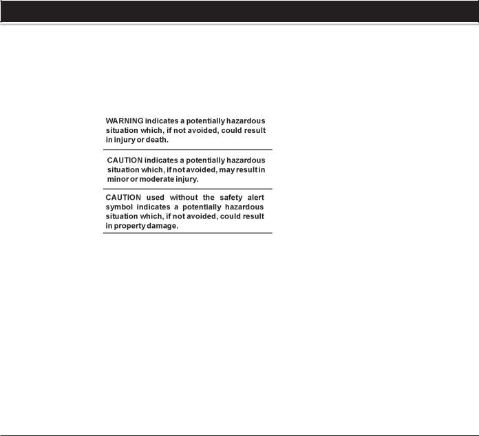
Your safety and the safety of others is extremely important in the installation, use and servicing of this water heater.
Many safety-related messages and instructions have been provided in this manual and on your own water heater to warn you and others of a potential injury hazard. Read and obey all safety messages and instructions throughout this manual. It is very important that the meaning of each safety message is understood by you and others who install, use or service this water heater.
All safety messages will generally tell you about the type of hazard, what can happen if you do not follow the safety message and how to avoid the risk of injury.
IMPORTANT DEFINITIONS
•Maytag Customer Service Center: The Maytag Customer Service Center has the ability equivalent to a licensed tradesman in the fields of plumbing, air supply, venting and gas supply, including a thorough understanding of the requirements of the Natural Gas and Propane Installation Code B149.1 as it relates to the installation of gas fired water heaters. The Service Center also has a thorough understanding of this instruction manual, and is able to perform repairs strictly in accordance with the service guidelines provided by the manufacturer.
•Gas Supplier: The Natural Gas or Propane Utility or service who supplies gas for utilization by the gas burning appliances within this application. The gas supplier typically has responsibility for the inspection and code approval of gas piping up to and including the Natural Gas meter or Propane storage tank of a building. Many gas suppliers also offer service and inspection of appliances within the building.
2
SAFETY PRECAUTIONS
3

TABLE OF CONTENTS |
|
SAFE INSTALLATION, USE AND SERVICE .................................................................................................................................... |
2 |
SAFETY PRECAUTIONS ................................................................................................................................................................. |
3 |
TABLE OF CONTENTS .................................................................................................................................................................... |
4 |
CUSTOMER RESPONSIBILITIES ................................................................................................................................................... |
5 |
PRODUCT SPECIFICATIONS ......................................................................................................................................................... |
5 |
MATERIALS AND BASIC TOOLS NEEDED .................................................................................................................................... |
6 |
TYPICAL INSTALLATION .............................................................................................................................................................. |
7-8 |
INSTALLATION INSTRUCTIONS .............................................................................................................................................. |
9-22 |
Removing the Old Water Heater ............................................................................................................................................. |
9 |
Facts to Consider About the Location ............................................................................................................................. |
10-11 |
Insulation Blankets ................................................................................................................................................................. |
11 |
Combustion Air and Ventilation for Appliances Located in Unconfined Spaces ............................................................. |
11 |
Combustion Air and Ventilation for Appliances Located in Confined Spaces ............................................................ |
11-12 |
Water Piping ...................................................................................................................................................................... |
13-14 |
Temperature-Pressure Relief Valve ..................................................................................................................................... |
14 |
Gas Piping ............................................................................................................................................................................... |
15 |
Sediment Traps ...................................................................................................................................................................... |
16 |
Filling the Water Heater ......................................................................................................................................................... |
16 |
Blower Assembly Installation ................................................................................................................................................ |
16 |
Vent Connections to Blower Assembly ................................................................................................................................. |
17 |
Venting and Installation ................................................................................................................................................... |
17-18 |
Condensation ......................................................................................................................................................................... |
18 |
Maximum Vent Lengths .......................................................................................................................................................... |
18 |
Venting ..................................................................................................................................................................................... |
19 |
Vent Terminal Installation ................................................................................................................................................ |
19-20 |
Vertical Vent Through Roof ..................................................................................................................................................... |
20 |
Vertical Vent Restrictions ....................................................................................................................................................... |
20 |
Vent Pipe Preparation ...................................................................................................................................................... |
21-22 |
OPERATING INSTRUCTIONS ................................................................................................................................................. |
23-24 |
Lighting and Operating Label ............................................................................................................................................... |
23 |
Temperature Regulation ........................................................................................................................................................ |
24 |
FOR YOUR INFORMATION ............................................................................................................................................................ |
25 |
Start Up Conditions ................................................................................................................................................................ |
25 |
Operational Conditions .......................................................................................................................................................... |
25 |
SERVICE AND ADJUSTMENT ................................................................................................................................................. |
26-27 |
Venting System Inspection .................................................................................................................................................... |
26 |
Burner Operation and Inspection ......................................................................................................................................... |
26 |
Burner Cleaning ..................................................................................................................................................................... |
26 |
Housekeeping ........................................................................................................................................................................ |
26 |
Anode Rod Inspection ............................................................................................................................................................ |
27 |
Temperature-Pressure Relief Valve Operation ................................................................................................................... |
27 |
Draining ................................................................................................................................................................................... |
27 |
Drain Valve Washer Replacement ........................................................................................................................................ |
27 |
Service ..................................................................................................................................................................................... |
27 |
LEAKAGE CHECKPOINTS ............................................................................................................................................................ |
28 |
TROUBLESHOOTING GUIDELINES ...................................................................................................................................... |
29-30 |
PARTS ORDER LIST ...................................................................................................................................................................... |
31 |
WARRANTY ..................................................................................................................................................................................... |
32 |
4

CUSTOMER RESPONSIBILITIES
Thank You for purchasing a Maytag water heater. Properly installed and maintained, it should give you years of trouble free service. It is strongly suggested that this new water heater be professionally installed, contact Maytag Customer Service (1-800-788-8899) for recommended installers.
Abbreviations Found In This Instruction Manual:
•CSACanadian Standards Association
•ANSI -American National Standards Institute
•ASME - American Society of Mechanical Engineers
•UL - Underwriters Laboratories Inc.
This gas-fired water heater is listed by Underwriters Laboratories Inc. underAmerican National Standard/CSAStandard for Gas Water Heaters ANSI Z21.10.1 • CSA 4.1 (current edition).
PREPARING FOR THE INSTALLATION
1.Read the “Safety Precautions” section, page 3 of this manual first and then the entire manual carefully. If you don’t follow the safety rules, the water heater will not operate properly. It could cause DEATH,SERIOUSBODILYINJURYAND/ORPROPERTYDAMAGE.
This manual contains instructions for the installation, operation, and maintenance of the gas-fired water heater. It also contains warnings throughout the manual that you must read and be aware of. All warnings and all instructions are essential to the proper operation
of the water heater and your safety. Since we cannot put everything on the first few pages, READ THE ENTIRE MANUAL BEFORE
ATTEMPTING TO INSTALLOR OPERATETHE WATERHEATER.
2.The installation must conform with these instructions and the local code authority having jurisdiction. In the absence of local codes, installations shall comply with the Natural Gas and Propane Installation Code CAN/CSA B149.1 and The Canadian Electric Code CSA C22.1. These publications are available from Canadian Standards Association, 5060 Spectrum Way, Suite 100, Mississauga, Ontario, Canada L4W 5N6.
3.The water heater when installed must be grounded in accordance with the local codes, or in the absence of local codes, the Canadian Electric Code CSA C22.1.
4.If after reading this manual you have any questions or do not understand any portion of the instructions, call the local gas utility or
Maytag Customer Service at 1-800-788-8899 for an authorized servicer.
5.Carefully plan the place where you are going to put the water heater. Correct combustion, vent action, and vent pipe installation are very important in preventing death from possible carbon monoxide poisoning and fires.
Examine the location to ensure the water heater complies with the “Facts to ConsiderAbout the Location” section in this manual.
PRODUCT SPECIFICATIONS
|
TANK |
|
|
RECOVERY |
MINIMUM |
|
|
|
CAPACITY |
|
INPUT |
RATE GALS. |
VENTPIPE |
DIAMETER |
DIMENSIONSIN |
MODEL |
IN GALS. |
TYPEOF |
RATE |
PERHOUR |
INCHES |
INCHES |
INCHES(mm)HEIGHT |
NUMBER |
(LTRS) |
GAS |
(Btu/hr) |
@90°FRISE |
(mm) |
(mm) |
TOJACKETTOP |
|
|
|
|
|
|
|
|
HVN41240PCGA |
40 (151) |
NATURAL |
40,000 |
44 |
2 (51) |
20 1/2 (521) |
55 (1,397) |
|
|
|
|
|
|
|
|
HVN41250PCGA |
50 (189) |
NATURAL |
40,000 |
44 |
2 (51) |
22 (559) |
56 3/4 (1,441) |
|
|
|
|
|
|
|
|
HVN41250VCGA |
50 (189) |
NATURAL |
50,000 |
53 |
2 (51) |
22 (559) |
56 3/4 (1,441) |
|
|
|
|
|
|
|
|
HVP41240PCGA |
40 (151) |
PROPANE |
40,000 |
44 |
2 (51) |
20 1/2 (521) |
55 (1,397) |
|
|
|
|
|
|
|
|
HVP41250PCGA |
50 (189) |
PROPANE |
40,000 |
44 |
2 (51) |
22 (559) |
56 3/4 (1,441) |
|
|
|
|
|
|
|
|
HVP41250VCGA |
50 (189) |
PROPANE |
50,000 |
53 |
2 (51) |
22 (559) |
56 3/4 (1,441) |
|
|
|
|
|
|
|
|
5
MATERIALS AND BASIC TOOLS NEEDED
Accessories
To simplify the installation Maytag has available the installation parts shown below. You may or may not need all of these accessories depending on your type of installation. Call Maytag Customer Service at 1-800-788-8899 for an authorized installer.
EXPANSION TANKS FOR THERMAL EXPANSION CONDITIONS AVAILABLE IN 2 GALLONS (7.6 LITERS), Part No. 66001013AND 5 GALLONS (18.9 LITERS), Part No. 66001014 CAPACITY.
DRAIN PANS AVAILABLE IN 22” (559 mm) DIAMETER (PART NO. 66001011) FOR WATER HEATERS HAVING A DIAMETER 20” (508 mm) OR LESS, 24” (610mm) DIAMETER (PART NO. 66001105) FOR WATERHEATERSHAVINGADIAMETER22”(559mm)ORLESSAND 28”(711mm)DIAMETER(PARTNO.66001012)FORWATERHEATERS HAVING A DIAMETER 26” (660 mm) OR LESS.
Tools
You may or may not need all these tools, depending on your type of installation. These tools can be purchased at your local hardware store.
•Pipe Wrenches (2) 14” (356 mm)
•Screwdriver
•Tin Snips
•6’ (1.82 m) Tape or Folding Ruler
•Garden Hose
•Drill
•Pipe Dope or Teflon Tape
DRILL
SLOT-HEAD SCREWDRIVER
TIN SNIPS
PHILLIPS SCREWDRIVER
ROLL OF TEFLON |
PIPE DOPE |
|
(SQUEEZE TUBE) |
||
TAPE (USE ONLY ON |
||
USE FOR WATER AND GAS |
||
WATER HEATER |
||
CONNECTIONS |
||
CONNECTIONS) |
||
|
GARDEN HOSE |
6 FOOT TAPE |
PIPE WRENCH |
Additional Tools Needed
When Sweat Soldering
•Tubing Cutters or Hacksaw
•Propane Torch
•Soft Solder
•Solder Flux
•Emery Cloth
•Wire Brushes
|
PROPANE |
TUBING CUTTER |
TORCH |
|
ROLL OF |
HACKSAW |
EMERY CLOTH |
3/4” (19 mm) WIRE BRUSH |
|
|
|
ROLL OF LEAD-FREE |
SOLDER |
1/2” (13 mm) WIRE BRUSH |
SOFT SOLDER |
FLUX |
6

TYPICAL INSTALLATION
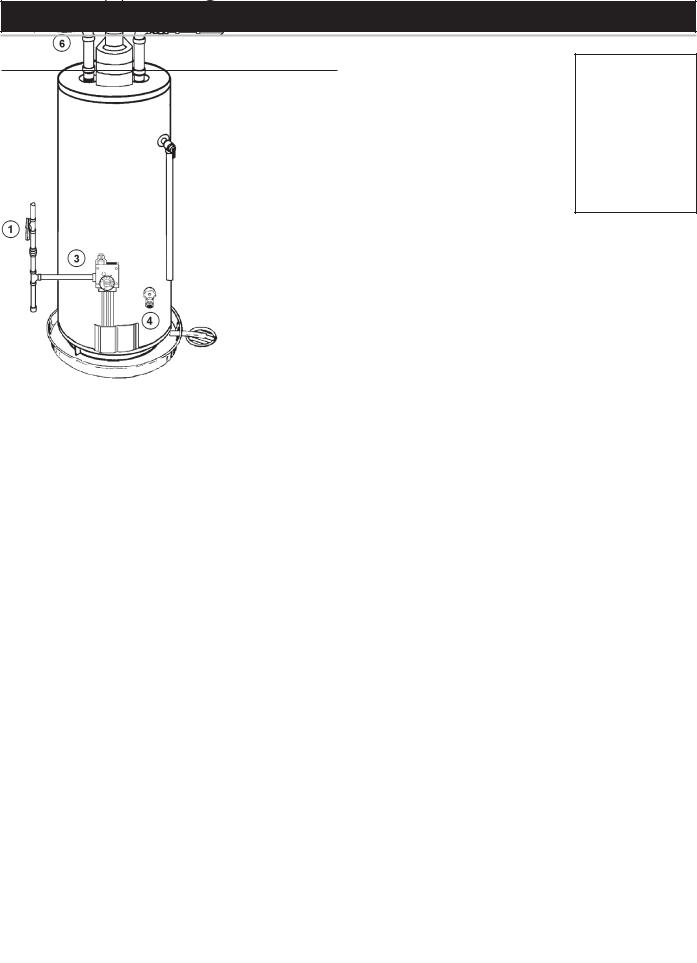
GET TO KNOW YOUR WATER HEATER - GAS MODELS
A |
Vent Pipe–Exhaust |
K |
Hot Water Outlet |
V |
Drip Leg (Sediment Trap) |
B |
Vent Terminal |
L |
Outlet Receptacle (115 VAC) |
W |
Drain Valve |
C |
Vent Adapter-Rubber Boot |
M |
Temperature-Pressure Relief Valve |
X |
Gas Valve-Thermostat |
D |
Blower Assembly |
N |
Flue |
Y |
Drain Pan |
E |
Cold Water Inlet |
O |
Flue Baffle Assembly** |
Z |
Air Intake Screen - Base Pan |
F |
Inlet Water Shut-off Valve |
P |
Insulation |
AA |
Inner Door |
G |
Union |
Q |
Control Harness |
BB |
Outer Door |
H |
Inlet Dip Tube |
R |
Rating Plate |
CC |
HSI Burner Assembly |
J |
Anode** |
S |
Gas Supply |
DD |
Air Intake Screen - |
|
|
T |
Manual Gas Shut-off Valve |
|
Blower Assembly |
|
|
U |
Ground Joint Union |
EE |
FV Sensor Assembly |
*ALL PIPING MATERIALS TO BE SUPPLIED BY CUSTOMERS.
**LOCATED UNDER THE BLOWER ASSEMBLY.
NATURAL HOT SURFACE IGNITER & MAIN BURNER
HOT
SURFACE
IGNITOR
SENSOR
PROPANE HOT SURFACE IGNITER & MAIN BURNER
HOT
SURFACE
IGNITOR
SENSOR
TEMPERATURE INDICATORS
*CAUTION: 115 VAC IN CONTROL HARNESS AND INSIDE OUTER DOOR
GAS MODELS
WITH HOT SURFACE IGNITION
& 2", 3" OR 4" PVC VENT CAPABILITY
FIGURE1.
7
TYPICAL INSTALLATION
MIXING VALVE USAGE
FIGURE2.
HOTTERWATERCANSCALD:
Water heaters are intended to produce hot water. Water heated to a temperature which will satisfy space heating, clothes washing, dish washing, and other sanitizing needs can scald and permanently injure you upon contact. Some people are more likely to be permanently injured by hot water than others. These include the elderly, children, the infirm, or physically/mentally handicapped. If anyone using hot water in your home fits into one of these groups or if there is a local code or province law requiring a certain temperature water at the hot water tap, then you must takespecialprecautions.Inadditiontousingthelowestpossibletemperature setting that satisfies your hot water needs, a means such as a *Mixing Valve, shall be used at the hot water taps used by these people or at the water heater. Mixing valves are available at plumbing supply or hardware stores. Consult Maytag Customer Service (1-800-788-8899). Follow mixing valve manufacturer’s instructions for installation of the valves. Before changing the factory setting on the thermostat, read the “Temperature Regulation” section in this manual, see Figure 26.
8
INSTALLATION INSTRUCTIONS
Removing the Old Water Heater
FIGURE3. |
|
|
1. Turn “OFF” the gas supply to the water |
|
|
|
||
heater. |
|
|
If the main gas line Shut-off valve |
|
|
serving all gas appliances is used, also |
|
|
shut “OFF” the gas at each appliance. |
|
|
Leave all gas appliances shut “OFF” |
|
|
until the water heater installation is |
|
|
|
||
completed, see Figures 3 and 4. |
FIGURE4. |
|
2. Turn “OFF” the water supply to the |
|
|
|
||
water heater at the water shut off |
|
|
valve or water meter. Some |
|
|
installations require that the water be |
|
|
turned off to the entire house, see |
|
|
Figures 3 and 5. |
|
|
FIGURE5. |
||
|
3.Check again to make sure the gas supply is “OFF” to the water heater. Then disconnect the gas supply connection from the gas control valve.
4.Attach a hose to the water heater drain valve and put the other end in a floor drain or outdoors. Open the water heater drain valve. Open a nearby hot water faucet which will relieve pressure in the water heater and speed draining. The water passing out of the drain valve may be extremely hot. To avoid being scalded, make sure all connections are tight and that the water flow is directed away from any person, see Figures 3 and 6.
FIGURE6.
5.Disconnect the vent pipe from the blower assembly where it connects to the water heater. In most installations the vent pipe can be lifted off
after any screw or other attached devices are removed. Make sure existing vent complies with maximum and minimum vent lengths on page 18.
6.If you have copper piping to the water heater, the two copper water pipes can be cut with a hacksaw approximately four inches away from where they connect to the water heater, see Figure 7. This will avoid cutting off pipes too short. Additional cuts can be made later if necessary. Disconnect the temperature-pressure relief valve drain line. When the water heater is drained, disconnect the hose from the drain valve. Close the drain valve. The water heater is now completely disconnected and ready to be removed.
FIGURE7.
If you have galvanized pipes to the water heater, loosen the two galvanized pipes with a pipe wrench at the union in each line. Also disconnect the piping remaining to the water heater, see Figure 8. These pieces should be saved since they may be needed when reconnecting the new water heater. Disconnect the temperaturepressure relief valve drain line. When the water heater is drained, disconnect the hose from the drain valve. Close the drain valve. The water heater is now completely disconnected and ready to be removed. Mineral buildup or sediment may have accumulated in the old water heater. This causes the water heater to be much heavier than normal and this residue, if spilled out, could cause staining.
FIGURE8.
9
FACTS TO CONSIDER ABOUT THE LOCATION
Carefully choose an indoor location for the new water heater, because the placement is a very important consideration for the safety of the occupants in the building and for the most economical use of the appliance.
This water heater is not for use in manufactured (mobile) homes or outdoor installation.
Whether replacing an old water heater or putting the water heater in a new location, the following critical points must be observed:
1.Select a location indoors as close as practical to the vent terminal or location to which the water heater vent piping is going to be connected, and as centralized with the water piping system as possible.
2.Selected location must provide adequate clearances for servicing and proper operation of the water heater.
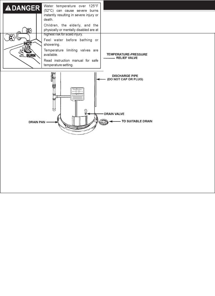
Installation of the water heater must be accomplished in such a manner that if the tank or any connections should leak, the flow will not cause damage to the structure. For this reason, it is not advisable to install the water heater in an attic or upper floor. When such locations cannot be avoided, a suitable drain pan should be installed under the water heater. Drain pans are available at your local hardware store. Such a drain pan must have a minimum length and width of at least 2" (5.1 cm) greater than the water heater dimensions and must be piped to an adequate drain. The pan must not restrict combustion air flow.
Water heater life depends upon water quality, water pressure and the environment in which the water heater is installed. Water heaters are sometimes installed in locations where leakage may result in property damage, even with the use of a drain pan piped to a drain. However, unanticipated damage can be reduced or prevented by a leak detector or water shut-off device used in conjunction with a piped drain pan. These devices are available from some plumbing supply wholesalers and retailers, and detect and react to leakage in various ways:
•Sensors mounted in the drain pan that trigger an alarm or turn off the incoming water to the water heater when leakage is detected.
•Sensors mounted in the drain pan that turn off the water supply to the entire home when water is detected in the drain pan.
•Water supply shut-off devices that activate based on the water pressure differential between the cold water and hot water pipes connected to the water heater.
•Devices that will turn off the gas supply to a gas water heater while at the same time shutting off its water supply.
INSTALLATIONS INAREAS WHERE FLAMMABLE LIQUIDS (VAPORS) ARELIKELYTOBEPRESENTORSTORED(GARAGES,STORAGEAND UTILITYAREAS, ETC.): Flammable liquids (such as gasoline, solvents, propane (LP or butane, etc.) and other substances (such as adhesives, etc.) emit flammable vapors which can be ignited by a gas water heater’s hot surface igniter or main burner. The resulting flashback and fire can cause death or serious burns to anyone in the area. This water heater is equipped with a FV sensor for detecting the presence of flammable vapors, see Figure 9. When the sensor detects those vapors, the unit will shut down and not operate. Should this happen, please refer to the troubleshooting guide on pages 33-34. Even though this water heater is a flammable vapors ignition resistant water heater and is designed to reduce the chances of flammable vapors being ignited, gasoline and other flammable substances should never be stored or used in the same vicinity or area containing a gas water heater or other open flame or spark producing appliance.
FIGURE9.
Also, the water heater must be located and/or protected so it is not subject to physical damage by a moving vehicle.
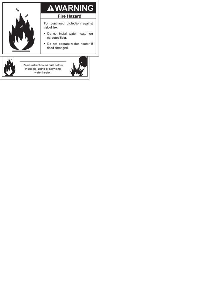
This water heater must not be installed directly on carpeting. Carpeting must be protected by metal or wood panel beneath the appliance extending beyond the full width and depth of the appliance by at least 3" (7.6 cm) in any direction, or if the appliance is installed in an alcove or closet, the entire floor must be covered by the panel. Failure to heed this warning may result in a fire hazard.
Minimum clearances between the water heater and combustible construction are 0 inch at the sides and rear, 5" (12.7 cm) from the front
10
 Loading...