


Maytag DAX3090AXB, DAX3000AXB, DAX3000AXQ, DAX3000AXW, DAX3090AXQ Installation Instructions
...JETCLEAN II WOOD PANEL KIT
DAX3000AX*/DAX3090AX*
Parts List:
1 EA INSTALLATION MANUAL
1 EA BEZEL
2 EA MOUNTING TRIM STRIPS
8 EA PANEL MOUNTING SCREWS
5 EA MOUNTING TAPE SQUARES
2 EA HEAVY DUTY SPRINGS
Tools you will need:
Circular Saw or Table Saw Tape Measure
Electric Drill
Torx (T-20) Head Screwdriver Phillips Head Screwdriver 1/8” Drill Bit
3/8” Drill Bit
Carpenter’s Glue (for use with 1/4” wood panels)
Masking Tape
Safety Glasses
Original Installation Instructions that came with your dishwasher
Things You Will Need to Know During the Installation:
• The Wood Panel Type you plan on installing: |
1/4” |
3/4” |
Part No. 6 918172 A |
1 |
INSTALLATION INSTRUCTIONS |

ALL ELECTRICAL WIRING, GROUNDING AND PLUMBING SHOULD BE DONE IN ACCORDANCE WITH NATIONAL AND LOCAL CODES BY QUALIFIED INDIVIDUALS.
CHECK LOCAL PLUMBING CODES
FOR APPROVED PLUMBING
PROCEDURES AND ACCESSORIES.
This appliance must be connected to a grounded metal, permanent wiring system; or an equipment-grounded conductor must be run with the circuit conductors and connected to the equipment-grounding terminal or lead on the appliance.
This dishwasher is designed for operation on an individual 120 VAC, 60 Hz grounded electrical circuit. Use required fuse (15 amp) or comparable circuit breaker. Two wire with ground service to the dishwasher is recommended for connection at the terminal box and for grounding.
BEFORE YOU BEGIN: In Step 5, the unit may need to be removed from the cabinet during the installation of the heavy-duty springs. A qualified electrician and/or plumber, as necessary, should be used to make any electrical or plumbing connections during that installation.
Panel Installation Instructions for a Jetclean II Dishwasher:
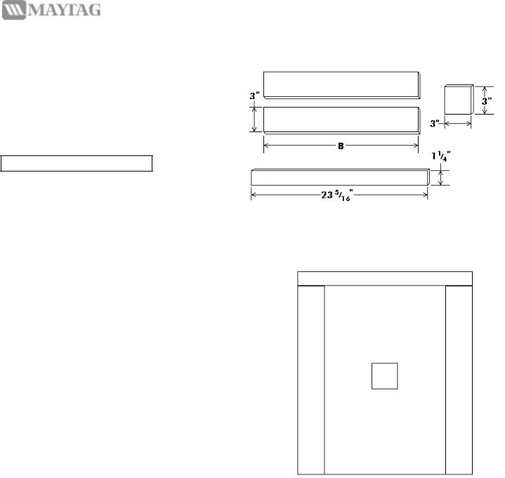
Step 1: Make the Wood Panel
•Cut the wood panel to the size shown in Figure 1. The height of your wood panel will be one of two sizes depending on which DAX Kit you have.
For DAX3000 Kits: Dimension A = 25”
For DAX3090 Kits: Dimension A = 25 15/16”
FIGURE 1- Panel Dimensions
Part No. 6 918172 A |
2 |
DAX3000AX*/DAX3090AX* |
Step 1.1: For 1/4” Wood Panels ONLY.
 For 3/4” Thick Wood Panels, go to Step 1.2.
•In addition to the rectangular face of the wood panel, you will need to cut the pieces shown in Figure 2.
Note: All pieces are 1/2” thick.
For DAX3000 Kits: Dimension B = 24 3/4”
For DAX3090 Kits: Dimension B = 23 11/16”
Figure 2 – Shim Dimensions
•Glue the shims you just made to the back of the 1/4” thick wood panel as shown in Figure 3 using Carpenter’s glue (yellow glue). With a damp rag, wipe up any excess glue squeezed out while the glue is still wet.
•Apply gentle pressure and allow glue to dry fully before attempting to assemble the wood panel to the door. Drying time for the glue may be up to 24 hours. Read the glue bottle for more complete drying time information. After the glue has dried, it can be scraped off using a putty knife and sanded smooth, if necessary.
FIGURE 3 – Shim Placement Pattern
Step 1.2: All Wood Panel Types.
•In order to drill the holes to attach the bezel, you will need to use the bezel as a drill guide. Place the wood panel face down on your work surface with the top of the panel pointing at you.
•Align the bezel along the top of the wood panel, centered from left to right as it is shown in Figure 4. The tabs of the bezel now contact the back of the wood panel.
Part No. 6 918172 A |
3 |
DAX3000AX*/DAX3090AX* |
Step 1.2, cont’d:
FIGURE 4 – Alignment of the Bezel to the Panel or Top Shim
•Drill through the center of the holes in the tabs on the bottom of the bezel with the 1/8” drill bit. Drill far enough to locate the holes without drilling too deep. Do not drill more than 1/2” into the wood.
•Once you have marked the center of the holes with the 1/8” drill bit, come back with the 3/8” bit to cut the final size and the final depth of 1/2”.
TIP: Use masking tape on your drill bit to mark a maximum drill depth of 1/2” so you won’t drill all the way through your wood panel.
Step 2: Apply Panel to Door Temporarily.
•Disconnect power to dishwasher at the circuit breaker.
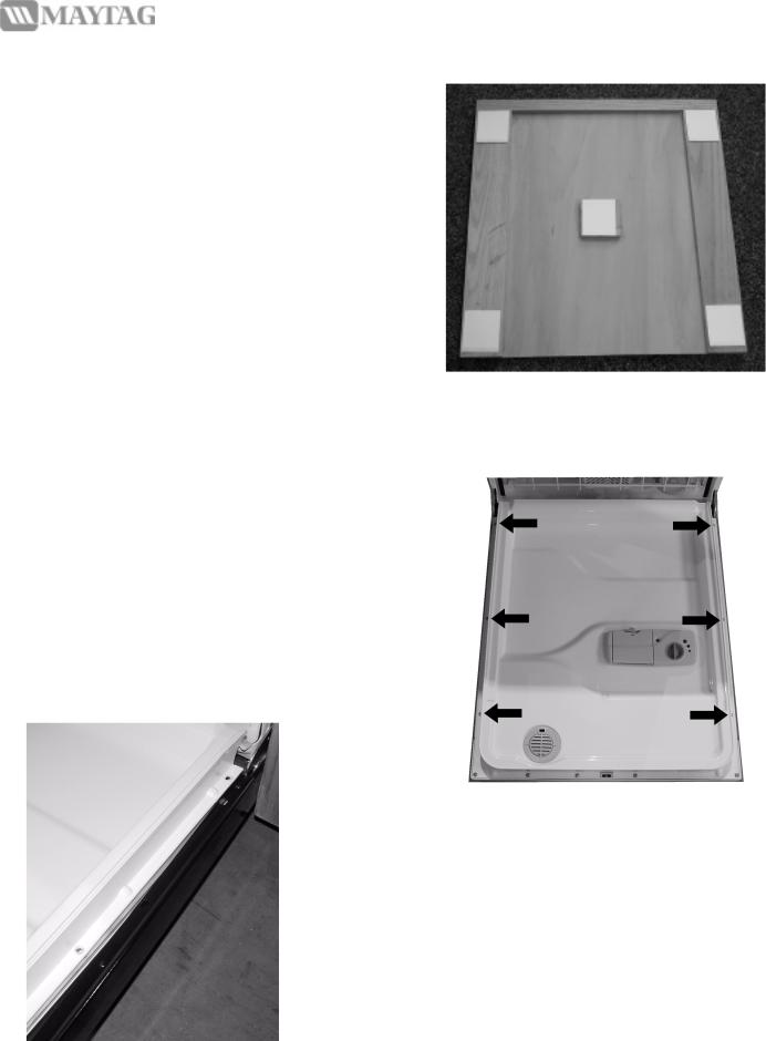
•Remove one side of the backer from tape strips and apply to the back of the panel in the locations shown in Figure 5.
TIP: Before removing the backing strips on the foam tape, try dry fitting the panel to the bezel. It will help improve your feel for the process before you apply the wood panel to the door. Once the sticky side of the foam tape has been pressed to the door, it can not be removed without damage to the foam tape.
Part No. 6 918172 A |
4 |
DAX3000AX*/DAX3090AX* |
Step 2, cont’d:
•Remove the backer material from all five (5) pieces of mounting tape now applied to the back of the wood panel.
•Slip the tabs on the upper edge of the bezel up under lower lip of the control panel.
•Center the wood panel under the bezel making sure the holes drilled near the top edge of the back side of the wood panel align with the posts protruding from the bottom tabs of the bezel. This will ensure the bezel and panel are aligned properly.
•Press the wood panel firmly onto the dishwasher to make sure the foam tape makes good contact.
FIGURE 5 – Foam Tape Placement
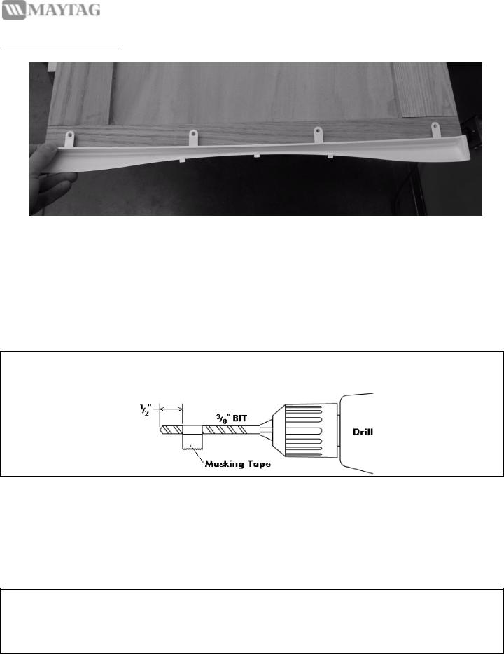
Step 3: Attach Mounting Trim to Door
•Carefully lower door until it is all the way down. It may now seem quite heavy. Later, you will adjust the springs to compensate for the weight of the door.
•Loosen the six (6) screws indicated in Figure 6 using the T-20 screwdriver until they are about 1/4” above the plastic Inner Door, or about 4 full turns.
FIGURE 6 – Mounting Screws to be Removed
•Insert the Mounting Trim Strip into the space provided between the plastic Inner Door and the Steel Outer Door that came with your dishwasher as is shown in Figure 7. Make sure the holes for the mounting screws line up with the holes in the steel Outer Door and the plastic Inner Door.
FIGURE 7 – Mounting Strip Placement
Part No. 6 918172 A |
5 |
DAX3000AX*/DAX3090AX* |
Step 3, cont’d:
•Retighten all six (6) screws you just loosened. Torque them until hand-tight.
•The Mounting Trim Strips should now wrap around the wood panel and the original outer portion of the door.
•Close and latch the door.
Step 4: Attach Mounting Trim to Wood Panel
•Drill pilot holes for the Panel Mounting Screws through the four (4) holes on each side in the Mounting Trim Strips using the 1/8” drill bit. Piloting the holes will help keep your wood from splitting where the screw enters.
•Drive the Panel Mounting Screws provided with the kit through the Mounting Trim Strips into the wood panel.
Step 5: Adjust Springs
Note: If your wood panel weighs more than 4 lbs., you will need the heavy-duty springs provided in this kit.
TIP: To prevent damage to the Toe Panel Assemblies, remove the four lower mounting screws using a 1/4” socket screwdriver or a Phillips head screwdriver and set the panels aside while you are adjusting the springs.
•Remove both of the Toe Panel Assemblies using a 1/4” socket screwdriver or a Phillips head screwdriver.
•Visually check to make sure you have enough slack in your electrical connection, water line connection and drain hose connection to remove the unit approximately one (1) foot.
Note: If you do not have enough slack in your connections, you will need to turn off the water beneath the sink and disconnect any necessary connections. Refer to your Original Installation Instructions for more information regarding the location of these connections. All electrical wiring, grounding and plumbing should be done in accordance with national and local codes by qualified individuals.
•Using a Phillips head screwdriver, remove the mounting screws from the side mounting strips attached to the cabinet pull the unit out of the cabinet approximately one (1) foot.
CAUTION: The top of the dishwasher should be held to prevent the dishwasher from tipping forward when the door is opened with the mounting screws removed.
Part No. 6 918172 A |
6 |
DAX3000AX*/DAX3090AX* |
Step 5, cont’d:
• Remove the original springs and replace them with the heavy-duty springs provided in your kit according to Table 8.
Total Wood |
No. of Original |
No. of Heavy-Duty |
Panel Weight |
Springs Needed |
Springs Needed |
|
|
|
0 to 4 Lbs. |
2 |
|
|
|
|
4 to 7 Lbs. |
1 |
1 |
|
|
|
7 to 13 Lbs. |
|
2 |
|
|
|
Table 8 – Spring Usage Based on Total Panel Weight
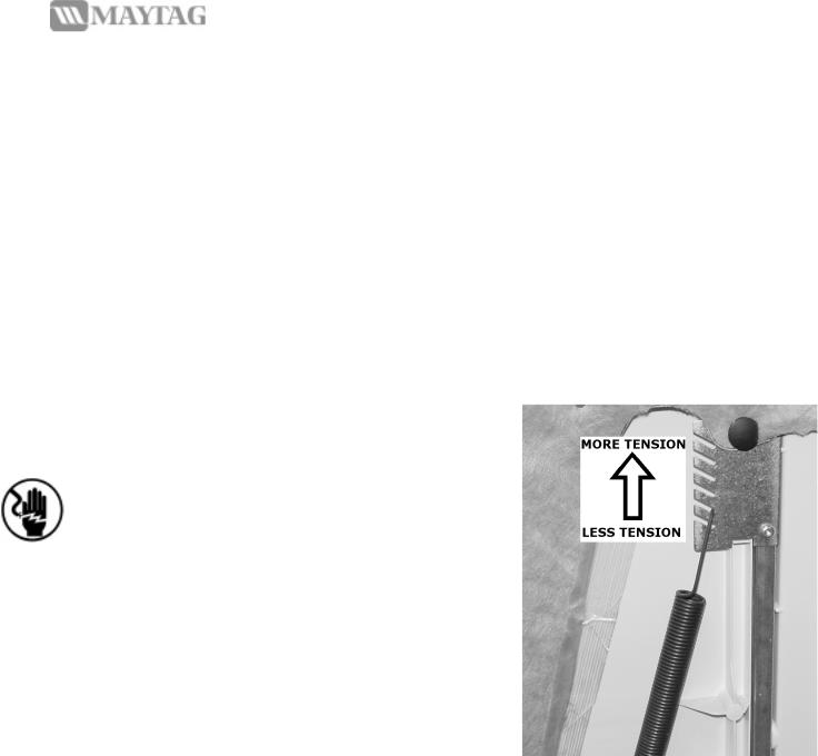
•Adjust the spring tension as shown in Figure 9 until the door moves up and down smoothly.
•Push the unit back into the cabinet and re-mount using the screws you just removed from the side mounting strips. Using your Original Installation Instructions, reconnect any electrical, water or drain connection you disconnected earlier.
•Be sure there are no leaks in any of the four (4) water or drain connection locations.
•Re-mount the Toe Kick Panel using the screws you removed when beginning the heavy-duty spring installation. Make sure the toe panel fits tightly against the floor.
•Re-mount the Toe Panel Assemblies to the frame.
FIGURE 9 – Spring Tension Adjustment
Step 6: Return power to dishwasher.
•Turn power to the dishwasher back on at the fuse or circuit breaker.
•The Dishwasher is ready to run.
•Run one (1) Rinse/ Hold cycle to verify that all connections are in place and working properly.
Part No. 6 918172 A |
7 |
DAX3000AX*/DAX3090AX* |
 Loading...