


 Loading...
/CZVQT & :-)$#6 2TQFWEV /CPWCN
0QXGODGT

© November 1, 2001 Maxtor Corporation. All rights reserved. Printed in U.S.A.
This publication could include technical inaccuracies or typographical errors. Changes are periodically made to the information herein – which will be incorporated in revised editions of the publication. Maxtor may make changes or improvements in the product(s) described in this publication at any time and without notice.
UL/CSA/VDE/TUV
UL standard 1954 recognition granted under File No. E78016
CSA standard C22.2-950 certification granted under File No. LR49896
TUV Rheinland EN 60 950
Tested to FCC Rules for Radiated and Conducted Emissions, Part 15, Sub Part J, for Class-B Equipment.
PATENTS
These products are covered by or licensed under one or more of the following U.S. Patents:
4,419,701; 4, 538,193 4,625,109; 4,639,798; 4,647,769; 4,647,997; 4,661,696; 4,669,004; 4,675,652; 4,703,176; 4,730,321; 4,772,974; 4,783,705; 4,819,153; 4,882,671; 4,920,442; 4,920,434; 4,982,296; 5,005,089; 5,027,241; 5,031,061; 5,084,791; 5,119,254; 5,160,865; 5,170,229; 5,177,771; Other U.S. and Foreign Patents Pending.
Maxtor®, MaxFax® and No Quibble Service® are registered trademarks of Maxtor Corporation, registered in the U.S.A. and other countries. Maxtor D540X-4K, AutoTransfer, AutoRead, AutoWrite, DisCache, DiskWare, Defect Free Interface, and WriteCache are trademarks of Maxtor Corporation. All other brand names or trademarks are the property of their manufacturers.
Maxtor reserves the right to make changes and improvements to its products, without incurring any obligation to incorporate such changes or improvements into units previously sold or shipped.
This product or document is protected by copyright and distributed under licences restricting its use, copying, distributing, and decompilation. No part of this product or document may be reproduced in any form by any means without prior written authorization of Maxtor and its licensors, if any.
RESTRICTED RIGHTS LEGEND: Use, duplication, or disclosure by the government is subject to restrictions as set forth in subparagraphs (c)(1)(ii) of the Rights in Technical Data and Computer Software clause at DFARS 252.227-7013 and FAR 52.227-19.
THIS PUBLICATION IS PROVIDED “AS IS” WITHOUT WARRANTY OF ANY KIND, EITHER EXPRESS OR IMPLIED, INCLUDING, BUT NOT LIMITED TO, THE IMPLIED WARRANTIES OF MERCHANTABILITY, FITNESS FOR A PARTIULAR PURPOSE, OR NON-INFRINGE- MENT.
You can request Maxtor publications from your Maxtor Sales Representative or order them directly from Maxtor.
Publication Number: 81-126201-02
Corporate Headquarters:
510 Cottonwood Drive
Milpitas, California 95035
Tel: 408-432-1700
Fax: 408-432-4510
Research and Development Center:
2190 Miller Drive
Longmont, Colorado 80501
Tel: 303-651-6000
Fax: 303-678-2165
$GHQTG ;QW $GIKP
Thank you for your interest in Maxtor hard disk drives. This manual provides technical information for OEM engineers and systems integrators regarding the installation and use of Maxtor hard drives. Drive repair should be performed only at an authorized repair center. For repair information, contact the Maxtor Customer Service Center at 800-2MAXTOR or 408-922-2085.
CAUTION: Maxtor hard drives are precision products. Failure to follow these precautions and guidelines outlined here may lead to product failure, damage and invalidation of all warranties.
1BEFORE unpacking or handling a drive, take all proper electro-static discharge (ESD) precautions, including personnel and equipment grounding. Stand-alone drives are sensitive to ESD damage.
2BEFORE removing drives from their packing material, allow them to reach room temperature.
3During handling, NEVER drop, jar, or bump a drive.
4Once a drive is removed from the Maxtor shipping container, IMMEDIATELY secure the drive through its mounting holes within a chassis. Otherwise, store the drive on a padded, grounded, antistatic surface.
5NEVER switch DC power onto the drive by plugging an electrically live DC source cable into the drive's connector. NEVER connect a live bus to the drive's interface connector.
6ELECTRICAL GROUNDING - For proper operation, the drive must be securely fastened to a device bay that provides a suitable electrical ground to the drive baseplate.
Please do not remove or cover up Maxtor factory-installed drive labels. They contain information required
should the drive ever need repair.

6CDNG QH %QPVGPVU
%JCRVGT |
|
|
|
#$176 6*+5 /#07#. |
|
||
1.1 |
AUDIENCE ............................................................................................................. |
1-1 |
|
1.2 |
MANUAL ORGANIZATION................................................................................ |
1-1 |
|
1.3 |
TERMINOLOGY AND CONVENTIONS ........................................................... |
1-1 |
|
1.4 |
REFERENCES ........................................................................................................ |
1-3 |
|
%JCRVGT |
|
|
|
)'0'4#. &'5%4+26+10 |
|
||
2.1 |
PRODUCT OVERVIEW ....................................................................................... |
2-1 |
|
2.2 |
KEY FEATURES..................................................................................................... |
2-2 |
|
2.3 |
Regulatory Compliance Standards ............................................................................. |
2-3 |
|
2.4 |
HARDWARE REQUIREMENTS ......................................................................... |
2-4 |
|
%JCRVGT |
|
|
|
+056#..#6+10 |
|
||
3.1 |
SPACE REQUIREMENTS ..................................................................................... |
3-1 |
|
3.2 |
UNPACKING INSTRUCTIONS........................................................................... |
3-2 |
|
3.3 |
HARDWARE OPTIONS ....................................................................................... |
3-4 |
|
|
3.3.1 |
Cable Select (CS) Jumper ................................................................................. |
3-5 |
|
3.3.2 |
Drive Select (DS) Jumper ................................................................................. |
3-6 |
|
3.3.3 |
Master Jumper configuration ............................................................................. |
3-6 |
|
3.3.4 Jumper Parking (PK) Position ........................................................................... |
3-6 |
|
|
3.3.5 |
Alternate Capacity (AC) ................................................................................... |
3-7 |
3.4 |
ATA BUS ADAPTER.............................................................................................. |
3-8 |
|
|
3.4.1 |
40-Pin ATA Bus Connector ............................................................................. |
3-8 |
|
3.4.2 |
Adapter Board .................................................................................................. |
3-8 |
3.5 |
MOUNTING THE DRIVE ON PERSONAL COMPUTERS .............................. |
3-9 |
|
|
3.5.1 |
Orientation ....................................................................................................... |
3-9 |
|
3.5.2 |
Clearance ....................................................................................................... |
3-11 |
|
3.5.3 |
Ventilation ..................................................................................................... |
3-11 |
3.6 |
COMBINATION CONNECTOR (J1)................................................................. |
3-11 |
|
|
3.6.1 DC Power (J1, Section A) .............................................................................. |
3-12 |
|
|
3.6.2 External Drive Activity LED .......................................................................... |
3-12 |
|
|
3.6.3 ATA Bus Interface Connector (J1, Section C) ................................................ |
3-12 |
|
3.7 |
FOR SYSTEMS WITH A MOTHERBOARD ATA ADAPTER ........................ |
3-13 |
|
3.8 |
FOR SYSTEMS WITH AN ATA ADAPTER BOARD ....................................... |
3-13 |
|
|
3.8.1 |
Adapter Board Installation ............................................................................... |
3-13 |
Maxtor D540X-4K 20.4/40.0/60.0/80.0 GB AT |
v |

Table of Contents
3.9 |
TECHNIQUES IN DRIVE CONFIGURATION ................................................ |
3-16 |
|
3.9.1 |
The 528-Megabytes Barrier ............................................................................ |
3-16 |
|
3.9.2 |
The 8.4-Gigabytes Barrier ............................................................................... |
3-16 |
|
3.9.3 |
Operating system limitations ........................................................................... |
3-17 |
|
3.10 |
SYSTEM STARTUP AND OPERATION ........................................................... |
3-17 |
|
%JCRVGT |
|
|
|
52'%+(+%#6+105 |
|
||
4.1 |
SPECIFICATION SUMMARY ............................................................................... |
4-1 |
|
4.2 |
FORMATTED CAPACITY .................................................................................... |
4-4 |
|
4.3 |
DATA TRANSFER RATES.................................................................................... |
4-4 |
|
4.4 |
TIMING SPECIFICATIONS................................................................................... |
4-5 |
|
4.5 |
POWER ................................................................................................................... |
4-6 |
|
4.5.1 |
Power Sequencing ............................................................................................ |
4-6 |
|
4.5.2 |
Power Reset Limits .......................................................................................... |
4-6 |
|
4.5.3 |
Power Requirements ........................................................................................ |
4-7 |
|
4.6 |
ACOUSTICS............................................................................................................ |
4-8 |
|
4.7 |
MECHANICAL ....................................................................................................... |
4-9 |
|
4.8 |
ENVIRONMENTAL CONDITIONS .................................................................... |
4-9 |
|
4.9 |
SHOCK AND VIBRATION ................................................................................. |
4-10 |
|
4.10 |
HANDLING the DRIVE ....................................................................................... |
4-11 |
|
4.11 |
RELIABILITY ........................................................................................................ |
4-11 |
|
4.12 |
ELECTROMAGNETIC SUSCEPTIBILITY......................................................... |
4-12 |
|
4.13 |
SPINDLE IMBALANCE ........................................................................................ |
4-12 |
|
4.14 |
DISK ERRORS ..................................................................................................... |
4-12 |
|
%JCRVGT |
|
|
|
$#5+% 24+0%+2.'5 1( 12'4#6+10 |
|
||
5.1 |
MAXTOR D540X-4K DRIVE MECHANISM....................................................... |
5-1 |
|
5.1.1 |
Base Casting Assembly ...................................................................................... |
5-3 |
|
5.1.2 |
DC Motor Assembly ......................................................................................... |
5-3 |
|
5.1.3 |
Disk Stack Assemblies ....................................................................................... |
5-3 |
|
5.1.4 |
Headstack Assembly .......................................................................................... |
5-5 |
|
5.1.5 |
Rotary Positioner Assembly .............................................................................. |
5-5 |
|
5.1.6 |
Automatic Actuator Lock .................................................................................. |
5-5 |
|
5.1.7 |
Air Filtration ..................................................................................................... |
5-6 |
|
5.2 |
DRIVE ELECTRONICS ......................................................................................... |
5-6 |
|
5.2.1 |
µProcessor ........................................................................................................ |
5-7 |
|
5.2.2 |
Digital Synchronous Spoke ............................................................................... |
5-7 |
|
5.2.3 Error Correction Code (ECC) Control ............................................................. |
5-7 |
||
5.2.4 |
Formatter .......................................................................................................... |
5-7 |
|
5.2.5 |
Buffer Controller .............................................................................................. |
5-8 |
|
vi Maxtor D540X-4K 20.4/40.0/60.0/80.0 GB AT

|
|
|
Table of Contents |
|
|
|
|
|
5.2.6 |
Servo Processor ................................................................................................ |
5-8 |
|
5.2.7 |
Read/Write Interface ....................................................................................... |
5-8 |
|
5.2.8 |
ATA Interface Controller ................................................................................. |
5-8 |
|
5.2.9 |
Motor Controller ............................................................................................. |
5-8 |
5.3 |
Read/Write ASIC ..................................................................................................... |
5-8 |
|
|
5.3.1 |
Pre-Compensator ............................................................................................. |
5-9 |
|
5.3.2 Variable Gain Amplifier (VGA) ........................................................................ |
5-9 |
|
|
5.3.3 |
Butterworth Filter ............................................................................................ |
5-9 |
|
5.3.4 FIR (Finite Impulse Response) Filter ................................................................ |
5-9 |
|
|
5.3.5 |
Flash A/D Converter ........................................................................................ |
5-9 |
|
5.3.6 |
Viterbi Detector ............................................................................................... |
5-9 |
|
5.3.7 |
ENDEC ........................................................................................................... |
5-9 |
|
5.3.8 |
Servo Processor ................................................................................................ |
5-9 |
|
5.3.9 |
Clock Synthesizer ............................................................................................. |
5-9 |
|
5.3.10 PLL .................................................................................................................. |
5-9 |
|
|
5.3.11 Serial Interface ................................................................................................ |
5-10 |
|
|
5.3.12 TA Detection and Correction ......................................................................... |
5-10 |
|
|
5.3.13 PreAmplifier and Write Driver ....................................................................... |
5-10 |
|
5.4 |
FIRMWARE FEATURES..................................................................................... |
5-10 |
|
|
5.4.1 |
Disk Caching .................................................................................................. |
5-10 |
|
5.4.2 Head and Cylinder Skewing ........................................................................... |
5-12 |
|
|
5.4.3 Error Detection and Correction ...................................................................... |
5-14 |
|
%JCRVGT |
|
|
|
#6# $75 +06'4(#%' #0& #6# %1//#0&5 |
|
||
6.1 |
INTRODUCTION ................................................................................................. |
6-1 |
|
6.2 |
MECHANICAL INTERFACE ................................................................................ |
6-1 |
|
|
6.2.1 |
Signal Cable and Connector ............................................................................. |
6-1 |
6.3 |
ELECTRICAL INTERFACE .................................................................................. |
6-1 |
|
|
6.3.1 |
ATA Bus Interface ............................................................................................ |
6-1 |
6.4 |
REGISTER ADDRESS DECODING ..................................................................... |
6-2 |
|
6.5 |
COMMAND INTERFACE..................................................................................... |
6-2 |
|
|
6.5.1 |
General Feature Set .......................................................................................... |
6-2 |
|
6.5.2 |
Multiword DMA .............................................................................................. |
6-3 |
|
6.5.3 Ultra DMA Feature Set .................................................................................... |
6-3 |
|
|
6.5.4 Power Management Feature Set ....................................................................... |
6-3 |
|
|
6.5.5 |
Security Mode Feature Set ................................................................................ |
6-4 |
|
6.5.6 Self-monitoring, Analysis, and Reporting (SMART) Feature Set ...................... |
6-4 |
|
|
6.5.7 Host Protected Area Feature Set ....................................................................... |
6-4 |
|
|
6.5.8 Automatic Acoustic Management Feature Set ................................................... |
6-4 |
|
|
6.5.9 |
IDENTIFY DEVICE Information .................................................................... |
6-5 |
|
6.5.10 SET FEATURES Supported Commands ......................................................... |
6-7 |
|
|
6.5.11 Maxtor Specific Commands .............................................................................. |
6-8 |
|
|
6.5.12 SMART READ ATTRIBUTE THRESHOLDS .......................................... |
6-15 |
|
|
6.5.13 Device Configuration Overlay Feature Set ...................................................... |
6-21 |
|
+0&': |
|
|
|
Maxtor D540X-4K 20.4/40.0/60.0/80.0 GB AT vii

.KUV QH (KIWTGU
Figure 3-1 Mechanical Dimensions of Maxtor D540X-4K Hard Disk Drive ................. |
3-1 |
|
Figure 3-2 |
Drive Packing Assembly ............................................................................... |
3-2 |
Figure 3-3 |
Drive Packing Assembly of a Polypropylene 20-Pack Container ................... |
3-3 |
Figure 3-4 |
Jumper Locations for the Maxtor D540X-4K Hard Disk Drive ..................... |
3-4 |
Figure 3-5 |
Jumper Locations on the Interface Connector ............................................... |
3-4 |
Figure 3-6 |
AT Connector and Jumper Location ............................................................ |
3-7 |
Figure 3-7 |
Mounting Dimensions for the Maxtor D540X-4K Hard Disk Drives ............ |
3-9 |
Figure 3-8 |
Mounting Screw Clearance for the Maxtor D540X-4K Hard Disk Drives .. |
3-10 |
Figure 3-9 |
J1 DC Power and ATA Bus Combination Connector ................................ |
3-11 |
Figure 3-10 |
Drive Power Supply and ATA Bus Interface Cables .................................... |
3-14 |
Figure 3-11 |
Completing the Drive Installation ............................................................... |
3-15 |
Figure 5-1 |
Maxtor D540X-4K AT Hard Disk Drive Exploded View .................................. |
5-2 |
Figure 5-2 |
Maxtor D540X-4K AT Hard Disk Drive Block Diagram ............................. |
5-6 |
viii |
Maxtor D540X-4K 20.4/40.0/60.0/80.0 GB AT |

.KUV QH 6CDNGU
Table 3-1 |
AT Jumper Options .............................................................................................. |
3-5 |
Table 3-2 |
J1 Power Connector, Section A .......................................................................... |
3-12 |
Table 3-3 |
Logical Addressing Format .................................................................................. |
3-18 |
Table 4-1 |
Specifications ........................................................................................................ |
4-1 |
Table 4-2 |
Formatted Capacity............................................................................................... |
4-4 |
Table 4-3 |
Timing Specifications............................................................................................ |
4-5 |
Table 4-4 |
Power Reset Limits............................................................................................... |
4-6 |
Table 4-5 |
Typical Power and Current Consumption............................................................. |
4-7 |
Table 4-6 |
Acoustical Characteristics—Sound Power.............................................................. |
4-8 |
Table 4-7 |
Environmental Specifications................................................................................. |
4-9 |
Table 4-8 |
Shock and Vibration Specifications...................................................................... |
4-10 |
Table 4-9 |
Error Rates ......................................................................................................... |
4-12 |
Table 5-1 |
Cylinder Contents................................................................................................. |
5-3 |
Table 5-1 |
Cylinder Contents................................................................................................. |
5-4 |
Table 5-2 |
Skew Offsets ....................................................................................................... |
5-13 |
Table 6-1 |
Identify Device Parameters.................................................................................... |
6-5 |
Table 6-2 |
Supported Features................................................................................................ |
6-7 |
Table 6-3 |
READ DEFECT LIST LENGTH Command Bytes ............................................. |
6-8 |
Table 6-4 |
READ DEFECT LIST Command Bytes .............................................................. |
6-9 |
Table 6-5 |
DEFECT LIST DATA FORMAT ..................................................................... |
6-10 |
Table 6-6 |
DEFECT ENTRY DATA FORMAT ............................................................... |
6-10 |
Table 6-7 |
Accessing the READ CONFIGURATION Command...................................... |
6-11 |
Table 6-8 |
Accessing the SET CONFIGURATION Command .......................................... |
6-12 |
Table 6-9 |
Accessing the SET CONFIGURATION WITHOUT |
|
|
SAVING TO DISK Command .......................................................................... |
6-12 |
Table 6-10 |
Configuration Command Format ........................................................................ |
6-13 |
Table 6-11 |
Device Attribute Thresholds Data Structure ....................................................... |
6-16 |
Table 6-12 |
Individual Threshold Data Structure ................................................................... |
6-17 |
Table 6-13 |
Device SMART Data Structure .......................................................................... |
6-17 |
Maxtor D540X-4K 20.4/40.0/60.0/80.0 GB AT |
ix |

Table of Contents
x Maxtor D540X-4K 20.4/40.0/60.0/80.0 GB AT
%JCRVGT
#$176 6*+5 /#07#.
This chapter gives an overview of the contents of this manual, including the intended audience, how the manual is organized, terminology and conventions, and references.
#7&+'0%'
The Maxtor D540X-4K 20.4/40.0/60.0/80.0 GB AT Product Manual is intended for several audiences. These audiences include: the end user, installer, developer, consumer electronics and personal computer original equipment manufacturer (CE/ PC OEM), and distributor. The manual provides information about installation, principles of operation, interface command implementation, and maintenance.
The Maxtor D540X-4K family of drives provide a high-quality, low-cost, market leading 40 GB per disk products to serve the consumer and mainstream commercial markets, as well as the consumer electronics market.
/#07#. 14)#0+<#6+10
This manual is organized into the following chapters:
•Chapter 1 – About This Manual
•Chapter 2 – General Description
•Chapter 3 – Installation
•Chapter 4 – Specifications
•Chapter 5 – Basic Principles of Operation
•Chapter 6 – ATA Bus Interface and ATA Commands
6'4/+01.1); #0& %108'06+105
In the Glossary at the back of this manual, you can find definitions for many of the terms used in this manual. In addition, the following abbreviations are used in this manual:
• ASIC |
application-specific integrated circuit |
Maxtor D540X-4K 20.4/40.0/60.0/80.0 GB AT 1-1

About This Manual
• |
ATA |
advanced technology attachment |
• |
bpi |
bits per inch |
• |
dB |
decibels |
• |
dBA |
decibels, A weighted |
• |
DPS |
Data Protection System |
• |
SPS |
Shock Protection System |
• |
ECC |
error correcting code |
• |
Kfci |
thousands of flux changes per inch |
• |
Hz |
hertz |
• |
KB |
kilobytes |
• |
LSB |
least significant bit |
• |
mA |
milliamperes |
• |
MB |
megabytes (1 MB = 1,000,000 bytes when referring to disk |
|
|
transfer rates or storage capacities and 1,048,576 bytes in all |
|
|
other cases) |
• |
Mb/s |
megabits per second |
• |
MB/s |
megabytes per second |
• |
MHz |
megahertz |
• |
ms |
milliseconds |
• |
MSB |
most significant bit |
• |
mV |
millivolts |
• |
ns |
nanoseconds |
• |
tpi |
tracks per inch |
• |
µs |
microseconds |
• |
V |
volts |
The typographical and naming conventions used in this manual are listed below. Conventions that are unique to a specific table appear in the notes that follow that table.
Typographical Conventions:
•Names of Bits: Bit names are presented in initial capitals. An example is the Host Software Reset bit.
•Commands: Interface commands are listed in all capitals. An example is WRITE LONG.
•Register Names: Registers are given in this manual with initial capitals. An example is the Alternate Status Register.
1-2 Maxtor D540X-4K 20.4/40.0/60.0/80.0 GB AT

About This Manual
•Parameters: Parameters are given as initial capitals when spelled out, and are given as all capitals when abbreviated. Examples are Prefetch Enable (PE), and Cache Enable (CE).
•Hexadecimal Notation: The hexadecimal notation is given in 9-point subscript form. An example is 30H.
•Signal Negation: A signal name that is defined as active low is listed with a minus sign following the signal. An example is RD–.
•Messages: A message that is sent from the drive to the host is listed in all capitals. An example is ILLEGAL COMMAND.
Naming Conventions:
•Host: In general, the system in which the drive resides is referred to as the host.
•Computer Voice: This refers to items you type at the computer keyboard. These items are listed in 10-point, all capitals, Courier font. An example is FORMAT C:/S.
" " #
For additional information about the ATA interface, refer to the latest revision of the draft standard on the internet at http://www.t13.org/ using the link under “1410D AT Attachment - 6 with Packet Interface (ATA/ATAPI - 6).”
Maxtor D540X-4K 20.4/40.0/60.0/80.0 GB AT 1-3

About This Manual
1-4 Maxtor D540X-4K 20.4/40.0/60.0/80.0 GB AT

%JCRVGT )'0'4#. &'5%4+26+10
This chapter summarizes the general functions and key features of the Maxtor D540X-4K 20.4/40.0/60.0/80.0 GB AT hard disk drives, as well as the applicable standards and regulations.
241&7%6 18'48+'9
Maxtor’s D540X-4K hard disk drives are part of a family of high performance, 1- inch-high hard disk drives manufactured to meet the highest product quality standards.
These hard disk drives use nonremovable, 3 1/2-inch hard disks and are available with the ATA interface.
The Maxtor D540X-4K 20.4/40.0/60.0/80.0 GB AT hard disk drives feature an embedded hard disk drive controller, and use ATA commands to optimize system performance. Because the drive manages media defects and error recovery internally, these operations are fully transparent to the user.
The innovative design of the Maxtor D540X-4K hard disk drives incorporate leading edge technologies such as UltraATA/100, Advanced Cache Management, Shock Protection System™II (SPS II), and Data Protection System (DPS). These enhanced technologies enable Maxtor to produce a family of high-performance, high-reliability drives.
Additionally, the Maxtor D540X-4K family of drives are CE-class drives designed for the consumer electronics market. Acoustics is one of the most important features in the CE arena. These hard disk drives are available with very quiet seek codes resulting in very low acoustical emissions from the drive. This makes the Maxtor D540X-4K drives an attractive choice for most CE users.
Maxtor D540X-4K 20.4/40.0/60.0/80.0 GB AT 2-1

General Description
-'; ('#674'5
The Maxtor D540X-4K 20.4/40.0/60.0/80.0 GB AT hard disk drives include the following key features:
General
•Formatted storage capacity of 20.4 GB (1 disk, 1 heads), 40.0 GB (1 disks, 2 heads), 60.0 (2 disks, 3 heads) and 80.0 (2 disks, 4 heads)
•Low profile, 1-inch height
•Industry standard 3 1/2-inch form factor
•Compliance with ANSI/NCITS interface standard for AT Attachment, revision 6 (ATA/ATAPI-6).
•Windows NT and 9X Certification
Performance
•Average seek time of 12 ms
•Average rotational latency of 5.56 ms
•New Ultra ATA interface with Maxtor-patented UltraATA/100 protocol supporting burst data transfer rates of 100 MB/s.
•Extra quiet seek code available (Maxtor Quiet Drive Technology)
•2 MB buffer
•Look-ahead DisCache feature with continuous prefetch and WriteCache write-buffering capabilities
•Read promotion and Write Reordering features
•AutoTask Register update, Multi-block AutoRead, and Multi-block AutoWrite features in a custom ASIC
•Support of all standard ATA data transfer modes with PIO mode 4 and multiword DMA mode 2, and Ultra DMA modes 0, 1, 2, 3, 4 and 5
Reliability
•800,000 hours mean time between failure (MTBF) in the field
•Automatic retry on read errors
•Error Correcting Code (ECC) with 15 symbols cross checking correction up to 142 bits in length
•S.M.A.R.T. 4 (Self-Monitoring, Analysis and Reporting Technology)
•Patented Airlock® automatic shipping lock, magnetic actuator retract, and dedicated landing zone
•Transparent media defect mapping
2-2 Maxtor D540X-4K 20.4/40.0/60.0/80.0 GB AT

General Description
•High performance, in-line defective sector skipping
•Reassignment of defective sectors discovered in the field, without reformatting
•Shock Protection System II to enhance protection against both operating and non-operating shock
•Data Protection System to verify drive integrity
Versatility
•Power saving modes
•Downloadable firmware
•Cable select feature
•Ability to daisy-chain two drives on the interface
Windows MS Logo Certification
•Passed Windows Me, Windows 98, Windows 2000, and Windows NT Workstation 4.0 Logo testing by Microsoft Windows Hardware Quality Labs (WHQL)
•Master ID# 43395
4GIWNCVQT[ %QORNKCPEG 5VCPFCTFU
Maxtor Corporation’s disk drive products meet all domestic and international product safety regulatory compliance requirements. Maxtor’s disk drive products conform to the following specifically marked Product Safety Standards:
•Underwriters Laboratories (UL) Standard 1950. This certificate is a category certification pertaining to all 3.5-inch drive models in the U.S.A. and Canada.
•TUV Rheinland Standard EN60 950. This certificate is a category certification pertaining to all 3.5-inch drive models.
2TQFWEV '/+ '/5 3WCNKHKECVKQPU
•CE Mark authorization is granted by TUV Rheinland in compliance with our qualifying under EN 55022:1994 and EN 50082-1:1997.
•C-Tick Mark is an Australian authorization marked noted on Maxtor’s disk drive products. The mark proves conformity to the regulatory compliance document AS/NZS 3548: 1995 and BS EN 55022: 1995.
•Approval from Taiwan BSMI. Number: 3892A638
•Korea EMI certification approved. MIC number: EH011-01-1977
Maxtor D540X-4K 20.4/40.0/60.0/80.0 GB AT 2-3

General Description
Maxtor’s disk drives are designed as a separate subassembly that conforms to the FCC Rules for Radiated and Conducted emissions, Part 15 Subpart J; Class B when installed in a given computer system.
*#4&9#4' 4'37+4'/'065
The Maxtor D540X-4K hard disk drives are compatible with computers and other hosts that support the ATA interface. It connects to the host either by means of a third-party ATA-compatible adapter board, or by plugging a cable from the drive directly into a PC motherboard that supplies an ATA interface.
2-4 Maxtor D540X-4K 20.4/40.0/60.0/80.0 GB AT
%JCRVGT +056#..#6+10
This chapter explains how to unpack, configure, mount, and connect the Maxtor D540X-4K 20.4/40.0/60.0/80.0 GB AT hard disk drive prior to operation. It also explains how to start up and operate the drive.
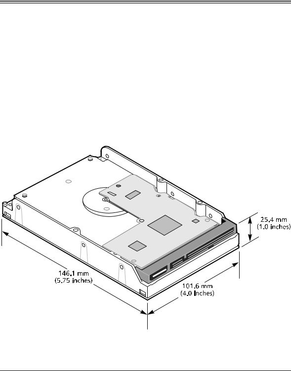
52#%' 4'37+4'/'065
The Maxtor D540X-4K hard disk drives are shipped without a faceplate. Figure 3- 1 shows the external dimensions of the Maxtor D540X-4K 20.4/40.0/60.0/80.0 GB AT drives.
(KIWTG Mechanical Dimensions of Maxtor D540X-4K Hard Disk Drive
Maxtor D540X-4K 20.4/40.0/60.0/80.0 GB AT |
3-1 |
Installation
702#%-+0) +05647%6+105
%#76+10 The maximum limits for physical shock can be exceeded if the drive is not handled properly. Special care should be
taken not to bump or drop the drive. It is highly recommended that Maxtor D540X-4K drives are not stacked or placed on any hard surface after they are unpacked. Such handling could cause media damage.
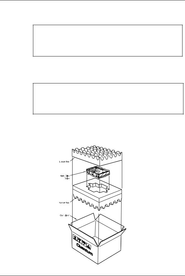
1.Open the shipping container and remove the packing assembly that contains the drive.
2.Remove the drive from the packing assembly.
%#76+10 During shipment and handling, the antistatic electrostatic discharge (ESD) bag prevents electronic component
damage due to electrostatic discharge. To avoid accidental damage to the drive, do not use a sharp instrument to open the ESD bag and do not touch PCB components. Save the packing materials for possible future use.
3. When you are ready to install the drive, remove it from the ESD bag.
Figure 3-2 shows the packing assembly for a single Maxtor D540X-4K hard disk drive. A 20-pack shipping container is available for multiple drive shipments.
(KIWTG Drive Packing Assembly
3-2 Maxtor D540X-4K 20.4/40.0/60.0/80.0 GB AT
Installation
(KIWTGDrive Packing Assembly of a Polypropylene 20-Pack Container
Note: The 20-pack container should be shipped in the same way it was received from Maxtor. When individual drives are shipped from the 20-pack container then it should be appropriately packaged (not supplied with the 20-pack) to prevent damage.
Maxtor D540X-4K 20.4/40.0/60.0/80.0 GB AT |
3-3 |

Installation
*#4&9#4' 126+105
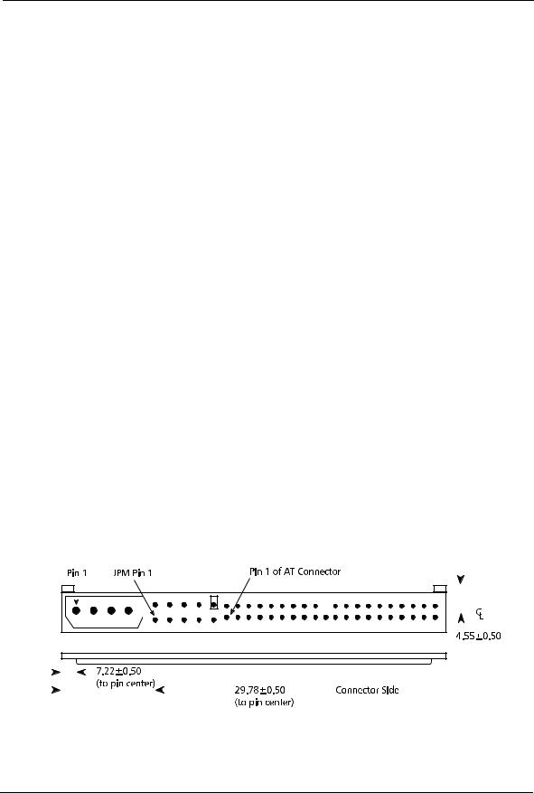
The configuration of a Maxtor D540X-4K 20.4/40.0/60.0/80.0 GB AT hard disk drive depends on the host system in which it is to be installed. This section describes the hardware options that you must take into account prior to installation. Figure 3- 4 shows the printed circuit board (PCB) assembly, indicating the jumpers that control some of these options.
(KIWTGJumper Locations for the Maxtor D540X-4K Hard Disk Drive
(KIWTGJumper Locations on the Interface Connector
3-4 Maxtor D540X-4K 20.4/40.0/60.0/80.0 GB AT

Installation
The configuration of the following four jumpers controls the drive’s modes of operation:
•CS – Cable Select
•DS – Drive Select
•PK– Jumper Parking Position (Slave mode)
•AC– Alternate Capacity
The AT PCB has two jumper locations provided to configure the drive in a system. The default configuration for the drive as shipped from the factory is with a jumper across the CS location, and open positions in the DS, PK and AC positions.
Table 3-1 defines the operation of the master-slave jumpers and their function relative to pin 28 on the interface. 1 indicates that the specified jumper is installed; 0 indicates that the jumper is not installed.
6CDNGAT Jumper Options
%5 |
&5 |
2- |
2+0 |
&'5%4+26+10 |
|
|
|
|
|
|
|
|
|
|
0 |
0 |
X |
X |
Drive is configured as a slave |
|
|
|
|
|
1 |
0 |
X |
Gnd |
Drive is configured as Master (Device 0) when |
|
|
|
|
attached to the end of a 80 conductor Ultra ATA |
|
|
|
|
cable |
|
|
|
|
|
0 |
1 |
X |
X |
Drive is configured as a Master |
|
|
|
|
|
1 |
0 |
X |
Open |
Drive is configured as a Slave (Device 1) when |
|
|
|
|
attached to the middle of a 80 conductor Ultra ATA |
|
|
|
|
cable |
|
|
|
|
|
1 |
1 |
X |
X |
Drive is configured as a Master with an attached slave |
|
|
|
|
that does not support DASP |
|
|
|
|
|
Note: In Table 3-1, a 0 indicates that the jumper is removed, a 1 indicates that the jumper is installed, and an X indicates that the jumper setting does not matter.
%CDNG 5GNGEV %5 ,WORGT
When a Maxtor D540X-4K 20.4/40.0/60.0/80.0 GB AT hard disk drive and another ATA hard disk drive are daisy-chained together, they can be configured as Master or Slave either by the CS or DS jumpers. To configure the drive as a Master or Slave with the CS feature, the CS jumper is installed (1). The drive's position on the 80 conductor Ultra ATA data cable then determines whether the drive is a Master (Device 0) or a Slave (Device 1). If the drive is connected to the end of the Ultra (cable Select) data cable the drive is a Master. If the drive is connected to the middle connection it is set as a Slave.
Maxtor D540X-4K 20.4/40.0/60.0/80.0 GB AT |
3-5 |

Installation
Once you install the CS jumper, the drive is configured as a Master or Slave by the state of the Cable Select signal: pin 28 of the ATA bus connector. Please note that pin 28 is a vendor-specific pin that Maxtor is using for a specific purpose. More than one function is allocated to CS, according to the ATA CAM specification (see reference to this specification in Chapter 1). If pin 28 is a 0 (grounded), the drive is configured as a Master. If it is a 1 (high), the drive is configured as a Slave. In order to configure two drives in a Master/Slave relationship using the CS jumper, you need to use a cable that provides the proper signal level at pin 28 of the ATA bus connector. This allows two drives to operate in a Master/Slave relationship according to the drive cable placement.
The Maxtor D540X-4K 20.4/40.0/60.0/80.0 GB AT hard disk drives are shipped from the factory as a Master (Device 0 - CS jumper installed). To configure a drive as a Slave (Device 1- DS scheme), the CS jumper must be removed. In this configuration, the spare jumper removed from the CS position may be stored on the PK jumper pins.
&TKXG 5GNGEV &5 ,WORGT
You can also daisy-chain two drives on the ATA bus interface by using their Drive Select (DS) jumpers. To use the DS feature, the CS jumper must not be installed.
To configure a drive as the Master (Device 0), a jumper must be installed on the DS pins.
Note: The order in which drives are connected in a daisy chain has no significance.
/CUVGT ,WORGT EQPHKIWTCVKQP
In combination with the current DS or CS jumper settings, the Slave Present (SP) jumper can be implemented if necessary as follows:
Note: The CS position doubles as the Slave present on this drive.
•When the drive is configured as a Master (DS jumper installed or CS jumper installed, and the Cable Select signal is set to (0), adding an additional jumper (both jumpers DS and CS now installed) will indicate to the drive that a Slave drive is present. This Master with Slave Present jumper configuration should be installed on the Master drive only if the Slave drive does not use the Drive Active/Slave Present (DASP–) signal to indicate its presence.
,WORGT 2CTMKPI 2- 2QUKVKQP
The PK position is used as a holding place for the jumper for a slave drive in systems that do not support Cable Select. The pins used for the parking position are vendor unique.
3-6 Maxtor D540X-4K 20.4/40.0/60.0/80.0 GB AT
Installation
#NVGTPCVG %CRCEKV[ #%
For user capacities below 66,055,248 sectors (32 GB), inserting the AC jumper limits the Number of Cylinders field to a value of 4,092, as reported in IDENTIFY DEVICE data word 1. This allows software drivers to determine that the actual capacity is larger than indicated by the maximum CHS, requiring LBA addressing to use the full capacity.
For larger user capacities above 66,055,248 sectors (32 GB), inserting the AC jumper limits the Total Number of User Addressable Sectors field to a value of 66,055,248, as reported in IDENTIFY DEVICE data words 60 and 61. This protects hosts which are not able to address beyond this capacity.
A summary of these effects for the Maxtor D540X-4K drives is shown in the following table:
|
|
|
|
|
|
|
|
|
#% ,7/2'4 176 |
|
|
|
#% ,7/2'4 +0 |
||||||||||||||||||
|
|
|
|
|
|
|
|
|
|
|
|
|
|
|
|
|
|
|
|
|
|
|
|
|
|
|
|
|
|
|
|
|
|
|
|
|
|
|
C=16,383 |
C=4,092 |
|||||||||||||||||||||||
)$ |
|
H=16 |
H=16 |
||||||||||||||||||||||||||||
|
S=63 |
S=63 |
|||||||||||||||||||||||||||||
|
|
|
|
|
|
|
LBA=39,876,480 |
LBA=39,876,480 |
|||||||||||||||||||||||
|
|
|
|
|
|
|
|
|
|
|
|
|
|
|
|
|
|
|
|
|
|
|
|
|
|
|
|
|
|
|
|
|
|
|
|
|
|
|
C=16,383 |
C=16,383 |
|||||||||||||||||||||||
)$ |
|
H=16 |
H=16 |
||||||||||||||||||||||||||||
|
S=63 |
S=63 |
|||||||||||||||||||||||||||||
|
|
|
|
|
|
|
|||||||||||||||||||||||||
|
|
|
|
|
|
|
LBA=78,198,750 |
LBA=66,055,248 |
|||||||||||||||||||||||
|
|
|
|
|
|
|
|
|
|
|
|
|
|
|
|
|
|
|
|
|
|
|
|
|
|
|
|
|
|
|
|
|
|
|
|
|
|
|
C=16,383 |
C=16,383 |
|||||||||||||||||||||||
)$ |
|
H=16 |
H=16 |
||||||||||||||||||||||||||||
|
S=63 |
S=63 |
|||||||||||||||||||||||||||||
|
|
|
|
|
|
|
|||||||||||||||||||||||||
|
|
|
|
|
|
|
LBA=117,266,688 |
LBA=66,055,248 |
|||||||||||||||||||||||
|
|
|
|
|
|
|
|
|
|
|
|
|
|
|
|
|
|
|
|
|
|
|
|
|
|
|
|
|
|
|
|
|
|
|
|
|
|
|
C=16,383 |
C=16,383 |
|||||||||||||||||||||||
)$ |
|
H=16 |
H=16 |
||||||||||||||||||||||||||||
|
S=63 |
S=63 |
|||||||||||||||||||||||||||||
|
|
|
|
|
|
|
|||||||||||||||||||||||||
|
|
|
|
|
|
|
LBA=156,301,488 |
LBA= 66,055,248 |
|||||||||||||||||||||||
|
|
|
|
|
|
|
|
|
|
|
|
|
|
|
|
|
|
|
|
|
|
|
|
|
|
|
|
|
|
|
|
|
|
|
|
|
|
|
|
|
|
|
|
|
|
|
|
|
|
|
|
|
|
|
|
|
|
|
|
|
|
|
|
|
|
|
|
|
|
|
|
|
|
|
|
|
|
|
|
|
|
|
|
|
|
|
|
|
|
|
|
|
|
|
|
|
|
|
|
|
|
|
|
|
|
|
|
|
|
|
|
|
|
|
|
|
|
|
|
|
|
|
|
|
|
|
|
|
|
|
|
|
|
|
|
|
|
|
|
|
|
|
|
|
|
|
|
|
|
|
|
|
|
|
|
|
|
|
|
|
|
|
|
|
|
|
|
|
|
|
|
|
|
|
|
|
|
|
|
|
|
|
|
|
|
|
|
|
|
|
|
|
|
|
|
|
|
|
|
|
|
|
|
|
|
|
|
|
|
|
|
|
|
|
|
|
|
|
|
|
|
|
|
|
|
|
|
|
|
|
|
|
|
|
|
|
|
|
|
|
|
|
|
|
|
|
|
|
|
|
|
|
|
|
|
|
|
|
|
|
|
|
|
|
|
|
|
|
|
|
|
|
|
|
|
|
|
|
|
|
|
|
|
|
|
|
|
|
|
|
|
|
|
|
|
|
|
|
|
|
|
|
|
|
|
|
|
|
|
|
|
|
|
|
|
|
|
|
|
|
|
|
|
|
|
|
|
|
|
|
|
|
|
|
|
|
|
|
|
|
|
|
|
|
|
|
|
|
|
|
|
|
|
|
|
|
|
|
|
|
|
|
|
|
|
|
|
|
|
|
|
|
|
|
|
|
|
|
|
|
|
|
|
|
|
|
|
|
|
|
|
|
|
|
|
|
|
|
|
|
|
|
|
|
|
|
|
|
|
|
|
|
|
|
|
|
|
|
|
|
|
|
|
|
|
|
|
|
|
|
|
|
|
|
|
|
|
|
|
|
|
|
|
|
|
|
|
|
|
|
|
|
|
|
|
|
|
|
|
|
|
|
|
|
|
|
|
|
|
|
|
|
|
|
|
|
|
|
|
|
|
|
|
|
|
|
|
|
|
|
|
|
|
|
|
|
|
|
|
|
|
|
|
|
|
|
|
|
|
|
|
(KIWTG AT Connector and Jumper Location
Maxtor D540X-4K 20.4/40.0/60.0/80.0 GB AT |
3-7 |

Installation
#6# $75 #'4
There are two ways you can configure a system to allow the Maxtor D540X-4K hard disk drives to communicate over the ATA bus of an IBM or IBM-compatible PC:
1.Connect the drive to a 40-pin ATA bus connector (if available) on the motherboard of the PC.
2.Install an IDE-compatible adapter board in the PC, and connect the drive
to the adapter board.
2KP #6# $WU %QPPGEVQT
Most PC motherboards have a built-in 40-pin ATA bus connector that is compatible with the 40-pin ATA interface of the Maxtor D540X-4K 20.4/40.0/60.0/80.0 GB AT hard disk drives. If the motherboard has an ATA connector, simply connect a 40-pin ribbon cable between the drive and the motherboard.
You should also refer to the motherboard instruction manual, and refer to Chapter 6 of this manual to ensure signal compatibility.
#FCRVGT $QCTF
If your PC motherboard does not contain a built-in 40-pin ATA bus interface connector, you must install an ATA bus adapter board and connecting cable to allow the drive to interface with the motherboard. Maxtor does not supply such an adapter board, but they are available from several third-party vendors.
Please carefully read the instruction manual that comes with your adapter board, as well as Chapter 6 of this manual to ensure signal compatibility between the adapter board and the drive. Also, make sure that the adapter board jumper settings are appropriate.
3-8 Maxtor D540X-4K 20.4/40.0/60.0/80.0 GB AT
Installation
/1706+0) 6*' &4+8' 10 2'4510#. %1/276'45
Drive mounting orientation, clearance, and ventilation requirements are described in the following subsections.
1TKGPVCVKQP
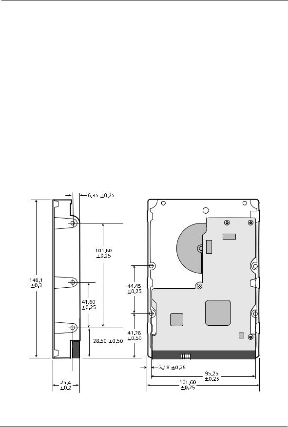
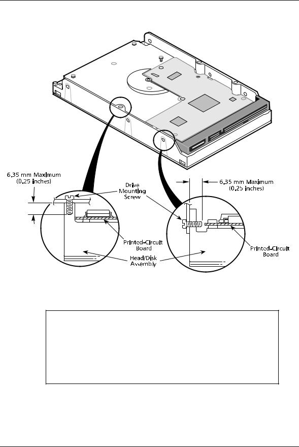
The mounting holes on the Maxtor D540X-4K 20.4/40.0/60.0/80.0 GB AT hard disk drives allow the drive to be mounted in any orientation. Figure 3-6 and Figure 3-7 show the location of the three mounting holes on each side of the drive. The drive can also be mounted using the four mounting hole locations on the PCB side of the drive.
Note: It is highly recommended that the drive is hard mounted on to the chassis of the system being used for general operation, as well as for test purposes. Failure to hard mount the drive can result in erroneous errors during testing.
Drives can be mounted in any orientation. Normal position is with the PCB facing down.
All dimensions are in millimeters. For mounting, #6-32 UNC screws are recommended.
(KIWTGMounting Dimensions for the Maxtor D540X-4K Hard Disk Drives
Maxtor D540X-4K 20.4/40.0/60.0/80.0 GB AT |
3-9 |
Installation
(KIWTG Mounting Screw Clearance for the Maxtor D540X-4K Hard Disk Drives
%#76+10 The PCB is very close to the mounting holes. Do not exceed the specified length for the mounting screws. The specified screw length allows full use of the mounting hole threads, while avoiding damaging or placing unwanted stress on the PCB. Figure 3-8 specifies the minimum clearance between the PCB and the screws in the mounting holes. To avoid stripping the mounting hole threads, the maximum torque applied to the screws must not exceed 8 inch-pounds. A maximum screw length of 0.25 inches may be used.
3-10 Maxtor D540X-4K 20.4/40.0/60.0/80.0 GB AT
Installation
%NGCTCPEG
Clearance from the drive to any other surface (except mounting surfaces) must be a minimum of 1.25 mm (0.05 inches).
8GPVKNCVKQP
The Maxtor D540X-4K 20.4/40.0/60.0/80.0 GB AT hard disk drives operate without a cooling fan, provided the ambient air temperature does not exceed 131° F (55° C) at any point along the drive form factor envelope.
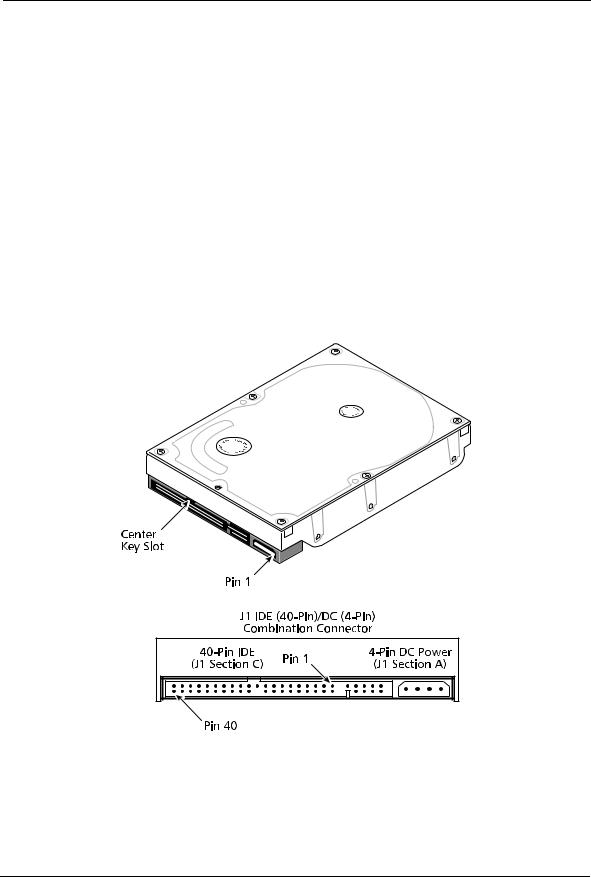
%1/$+0#6+10 %100'%614 ,
J1 is a three-in-one combination connector. The drive’s DC power can be applied to section A. The ATA bus interface (40-pin) uses section C. The connector is mounted on the back edge of the printed-circuit board (PCB), as shown in Figure 3-9.
(KIWTGJ1 DC Power and ATA Bus Combination Connector
Maxtor D540X-4K 20.4/40.0/60.0/80.0 GB AT 3-11
Loading...