


DiamondMax
Maxtor DiamondMax, 4320, 91728D8, 91512D7, 91303D6 User Manual
...
HARD DRIVE
P RODUCT
MANUAL
DiamondMax
™
4320
91728D8, 91512D7, 91303D6
91080D5 90845D4, 90648D3
90432D2

DiamondMax™ 4320
91728D8, 91512D7, 91303D6, 91080D5
90845D4, 90648D3, 90432D2
All material contained herein Copyright © 1998 Maxtor Corporation.
DiamondMax™, DiamondMax™ 1280, DiamondMax™ 1750,
DiamondMax™ 2160, DiamondMax™ 2880, DiamondMax™ 3400,
DiamondMax™ 4320, DiamondMax™ Plus 2500 and MaxFax™ are
trademarks of Maxtor Corporation. No Quibble
®
Service is a registered
trademark of Maxtor Corporation. Other brands or products are
trademarks or registered trademarks of their respective holders.
Contents and specifications subject to change without notice. All
rights reserved.
Corporate Headquarters
510 Cottonwood Drive
Milpitas, California 95035
Tel: 408-432-1700
Fax: 408-432-4510
Research and Development
Engineering Center
2190 Miller Drive
Longmont, Colorado 80501
Tel: 303-651-6000
Fax: 303-678-2165
Part #1407

Revisions Manual No. 1407

Before You Begin
Thank you for your interest in the Maxtor DiamondMax™ 4320 AT hard disk drives. This manual provides
technical information for OEM engineers and systems integrators regarding the installation and use of DiamondMax
hard drives.
Drive repair should be performed only at an authorized repair center. For repair information, contact
the Maxtor Customer Service Center at 800-2MAXTOR or 408-432-1700.
Before unpacking the hard drive, please review Sections 1 through 4.
CAUTION
Maxtor DiamondMax 4320 hard drives are precision products. Failure to
follow these precautions and guidelines outlined here may lead to
product failure, damage and invalidation of all warranties.
1
BEFORE unpacking or handling a drive, take all proper electro-static discharge (ESD)
precautions, including personnel and equipment grounding. Stand-alone drives are sensitive to
ESD damage.
2
BEFORE removing drives from their packing material, allow them to reach room
temperature.
3
During handling, NEVER drop, jar, or bump a drive.
4
Once a drive is removed from the Maxtor shipping container, IMMEDIATELY secure the drive
through its mounting holes within a chassis. Otherwise, store the drive on a padded, grounded,
antistatic surface.
5
NEVER switch DC power onto the drive by plugging an electrically live DC source cable into
the drive's connector. NEVER connect a live bus to the drive's interface connector.
Please do not remove or cover up Maxtor factory-installed drive labels.
They contain information required should the drive ever need repair.

DIAMONDMAX 4320 PRODUCT MANUAL
i
Contents
Section 1 — Introduction
Maxtor Corporation 1 - 1
Products 1 - 1
Support 1 - 1
Manual Organization 1 - 1
Abbreviations 1 - 1
Conventions 1 - 2
Key Words 1 - 2
Numbering 1 - 2
Signal Conventions 1 - 2
Section 2 — Product Description
The DiamondMax™ 4320
Product Features 2 - 2
Functional/Interface 2 - 2
Zone Density Recording 2 - 2
Read/Write Multiple Mode 2 - 2
UltraDMA - Mode 2 2 - 2
Multi-word DMA (EISA Type B) - Mode 2 2 - 2
Sector Address Translation 2 - 2
Logical Block Addressing 2 - 3
Defect Management Zone 2 - 3
On-the-Fly Hardware Error Correction Code (ECC) 2 - 3
Software ECC Correction 2 - 3
Automatic Head Park and Lock Operation 2 - 3
Cache Management 2 - 4
Buffer Segmentation 2 - 4
Read-Ahead Mode 2 - 4
Automatic Write Reallocation (AWR) 2 - 4
Write Cache Stacking 2 - 4
Major HDA Components 2 - 5
Drive Mechanism 2 - 5
Rotary Actuator 2 - 5
Read/Write Electronics 2 - 5
Read/Write Heads and Media 2 - 5
Air Filtration System 2 - 5
Microprocessor 2 - 5
Subsystem Configuration 2 - 6
Dual Drive Support 2 - 6
Cable Select Option 2 - 6
Jumper Location/Configuration 2 - 6
4092 Cylinder Limitation 2 - 6

DIAMONDMAX 4320 PRODUCT MANUAL
ii
Section 3 — Product Specifications
Models and Capacities 3 - 1
Drive Configuration 3 - 1
Performance Specifications 3 - 1
Physical Dimensions 3 - 2
Power Requirements 3 - 3
Power Mode Definitions 3 - 3
Spin-up 3 - 3
Seek 3 - 3
Read/Write 3 - 3
Idle 3 - 3
Standby 3 - 3
Sleep 3 - 3
EPA Energy Star Compliance 3 - 3
Environmental Limits 3 - 3
Shock and Vibration 3 - 4
Reliability Specifications 3 - 4
AFR 3 - 4
MTBF 3 - 4
Quality Acceptance Rate 3 - 4
Start/Stop Cycles 3 - 4
Data Reliability 3 - 4
Component Design Life 3 - 4
EMC/EMI 3 - 5
EMC Compliance 3 - 5
Canadian Emissions Statement 3 - 5
Safety Regulatory Compliance 3 - 5
Section 4 — Handling and Installation
Pre-formatted Drive 4 - 1
Important Notice 4 - 1
Hard Drive Handling Precautions 4 - 1
Electro-Static Discharge (ESD) 4 - 1
Unpacking and Inspection 4 - 2
Repacking 4 - 3
Physical Installation 4 - 3
Before You Begin 4 - 4
Please Read 4 - 4
Handling Precautions 4 - 4
Tools for Installation 4 - 4
Drive Identification Information 4 - 4
Capacity Barriers 4 - 4
Protecting Your Existing Data 4 - 4
General Requirements 4 - 5
System Hardware Requirements 4 - 5

DIAMONDMAX 4320 PRODUCT MANUAL
iii
BIOS Requirements 4 - 5
Ultra Direct Memory Access (UDMA) 4 - 5
OS Requirements for Large Capacity Hard Drives 4 - 5
Hard Drive Identification 4 - 6
Identifying IDE Devices on the Interface 4 - 6
Jumper Settings 4 - 6
Systems Using Cable Select 4 - 6
Relationship to Other IDE Devices 4 - 6
Mounting Drive in System 4 - 7
Attaching Interface and Power Cables 4 - 7
Attaching System Cables 4 - 7
System Setup 4 - 8
Setting the BIOS (CMOS) 4 - 8
BIOS (CMOS) Parameters 4 - 8
Hard Drive Preparation 4 - 10
System Hangs During Boot 4 - 12
Section 5 — AT Interface Description
Interface Connector 5 - 1
Pin Description Summary 5 - 1
Pin Description Table 5 - 2
PIO Timing 5 - 3
DMA Timing 5 - 4
Ultra DMA Timing Parameters 5 - 5
Section 6 — Host Software Interface
Task File Registers 6 - 1
Data Register 6 - 1
Error Register 6 - 1
Features Register 6 - 1
Sector Count Register 6 - 2
Sector Number Register 6 - 2
Cylinder Number Registers 6 - 2
Device/Head Register 6 - 2
Status Register 6 - 2
Command Register 6 - 3
Read Commands 6 - 3
Write Commands 6 - 3
Mode Set/Check Commands 6 - 3
Power Mode Commands 6 - 3
Initialization Commands 6 - 3
Seek, Format, and Diagnostic Commands 6 - 3
S.M.A.R.T. Commands 6 - 3
Summary 6 - 4
Control Diagnostic Registers 6 - 5

DIAMONDMAX 4320 PRODUCT MANUAL
iv
Alternate Status Register 6 - 5
Device Control Register 6 - 5
Digital Input Register 6 - 5
Reset and Interrupt Handling 6 - 6
Section 7 — Interface Commands
Command Summary 7 - 1
Read Commands 7 - 2
Read Sector(s) 7 - 2
Read Verify Sector(s) 7 - 2
Read Sector Buffer 7 - 2
Read DMA 7 - 3
Read Multiple 7 - 3
Set Multiple 7 - 3
Write Commands 7 - 4
Write Sector(s) 7 - 4
Write Verify Sector(s) 7 - 4
Write Sector Buffer 7 - 4
Write DMA 7 - 5
Write Multiple 7 - 5
Ultra DMA 7 - 5
Set Feature Commands 7 - 5
Set Features Mode 7 - 5
Power Mode Commands 7 - 7
Standby Immediate 7 - 7
Idle Immediate 7 - 7
Standby 7 - 7
Idle 7 - 7
Check Power Mode 7 - 7
Set Sleep Mode 7 - 7
Default Power-on Condition 7 - 7
Initialization Commands 7 - 9
Identify Drive 7 - 9
Initialize Drive Parameters 7 - 12
Seek, Format, and Diagnostic Commands 7 - 13
S.M.A.R.T. Command Set 7 - 14
Section 8 — Service and Support
Service Policy 8 - 1
No Quibble Service 8 - 1
Support 8 - 1
Glossary
Glossary GL - 1

DIAMONDMAX 4320 PRODUCT MANUAL
v
Figures
Figure Title Page
2 - 1 PCBA Jumper Location and Configuration 2 - 6
3 - 1 Outline and Mounting Dimensions 3 - 2
4 - 1 Multi-pack Shipping Container 4 - 2
4 - 2 Single-pack Shipping Container (Option A) 4 - 3
4 - 3 Single-pack Shipping Container (Option B) 4 - 3
4 - 4 Master, Slave and Cable Select Settings 4 - 5
4 - 5 5.25-inch Mounting Brackets and Rails 4 - 6
4 - 6 IDE Interface and Power Cabling Detail 4 - 7
4 - 7 Master, Slave and Cable Select Settings 4 - 10
5 - 1 Data Connector 5 - 1
5 - 2 PIO Data Transfer to/from Device 5 - 3
5 - 3 Multi-word DMA Data Transfer 5 - 4
5 - 4 Initiating an Ultra DMA Data In Burst 5 - 5
5 - 5 Sustained Ultra DMA Data In Burst 5 - 6
5 - 6 Host Pausing an Ultra DMA Data In Burst 5 - 6
5 - 7 Device Terminating an Ultra DMA Data In Burst 5 - 7
5 - 8 Host Terminating an Ultra DMA Data In Burst 5 - 7
5 - 9 Initiating an Ultra DMA Data Out Burst 5 - 8
5 - 10 Sustained Ultra DMA Data Out Burst 5 - 8
5 - 11 Device Pausing an Ultra DMA Data Out Burst 5 - 9
5 - 12 Host Terminating an Ultra DMA Data Out Burst 5 - 9
5 - 13 Device Terminating an Ultra DMA Data Out Burst 5 - 10
DIAMONDMAX 4320 – INTRODUCTION
1 – 1
SECTION 1
Introduction
Maxtor Corporation
Maxtor Corporation has been providing high-quality computer storage products since 1982. Along the way,
we’ve seen many changes in data storage needs. Not long ago, only a handful of specific users needed more than
a couple hundred megabytes of storage. Today, downloading from the Internet and CD-ROMs, multimedia,
networking and advanced office applications are driving storage needs even higher. Even home PC applications
need capacities measured in gigabytes, not megabytes.
Products
Maxtor’s products meet those demanding storage capacity requirements with room to spare. They feature
proven compatibility and reliability. While DiamondMax™ 4320 is the latest addition to our family of high
performance desktop hard drives, the DiamondMax™ 3400 series hard drives deliver industry-leading
capacity, performance and value for many PC applications.
Support
No matter which capacity, all Maxtor hard drives are supported by our commitment to total customer
satisfaction and our No Quibble
®
Service guarantee. One call – or a visit to our home page on the Internet
(http://www.maxtor.com) – puts you in touch with either technical support or customer service. We’ll
provide you the information you need quickly, accurately and in the form you prefer – a fax, a downloaded
file or a conversation with a representative.
Manual Organization
This hard disk drive reference manual is organized in the following method:
❏ Section 1 – Introduction
❏ Section 2 – Description
❏ Section 3 – Specifications
❏ Section 4 – Installation
❏ Section 5 – AT Interface
❏ Section 6 – Host Software Interface
❏ Section 7 – Interface Commands
❏ Section 8 – Service and Support
❏ Appendix – Glossary
Abbreviations
VRBBANOITPIRCSEDVRBBANOITPIRCSED
ATAtnemhcattaTABMetybagem
ipbhcnirepstibces/stibMdnocesrepstibagem
SHCrotces-daeh-rednilycces/BMdnocesrepsetybagem
bdslebicedzHMztrehagem
ABddethgiewA,slebicedsmdnocesillim
AMDsseccayromemtceridBSMtibtnacifingistsom
CCEedocnoitcerrocrorreVmstlovillim
icfhcnirepsegnahcxulfsnsdnocesonan
GnoitareleccaOIPtuptuo/tupnidemmargorp
BGetybagigMPRetunimrepsnoitulover
zHztrehipthcnirepskcart
BKetybolikAMDUsseccayromemtceridartlu
ABL)gni(sserddakcolblacigolcesµdnocesorcim
BSLtibtnacifingistsaelVstlov
AmserepmaillimWsttaw

DIAMONDMAX 4320 – INTRODUCTION
1 – 2
Conventions
If there is a conflict between text and tables, the table shall be accepted as being correct.
Key Words
The names of abbreviations, commands, fields and acronyms used as signal names are in all uppercase type
(e.g., IDENTIFY DRIVE). Fields containing only one bit are usually referred to as the “name” bit instead of
the “name” field.
Names of drive registers begin with a capital letter (e.g., Cylinder High register).
Numbering
Numbers that are not followed by a lowercase “b” or “h” are decimal values. Numbers that are followed by
a lowercase “b” (e.g., 01b) are binary values. Numbers that are followed by a lowercase “h” (e.g., 3Ah) are
hexadecimal values.
Signal Conventions
Signal names are shown in all uppercase type.
All signals are either high active or low active signals. A dash character (-) at the end of a signal name
indicates that the signal is low active. A low active signal is true when it is below ViL and is false when it is
above ViH. A signal without a dash at the end indicates that the signal is high active. A high active signal is
true when it is above ViH and is false when it is below ViL.
When a signal is asserted, it means the signal is driven by an active circuit to its true state.
When a signal is negated, it means the signal is driven by an active circuit to its false state.
When a signal is released, it means the signal is not actively driven to any state. Some signals have bias
circuitry that pull the signal to either a true or false state when no signal driver is actively asserting or negating
the signal. These instances are noted under the description of the signal.

PRODUCT DESCRIPTION
2 – 1
SECTION 2
Product Description
Maxtor DiamondMax™ 4320 AT disk drives are 1-inch high, 3.5-inch diameter random access storage devices
which incorporate an on-board ATA-4/Ultra DMA controller. High capacity is achieved by a balanced
combination of high areal recording density and the latest data encoding and servo techniques.
Maxtor's latest advancements in electronic packaging and integration methods have lowered the drive's power
consumption and increased its reliability. Advanced magneto-resistive read/write heads, an state-of-the-art head/
disk assembly using an integrated motor/spindle design allow up to four disks in a 3.5-inch package.
Exceptionally high data transfer rates and 9.0 ms access times make these performance series disk drives especially
well-suited to high speed desktop and server applications.
DiamondMax 4320 Key Features
ANSI ATA-4 compliant PIO Mode 4 interface (Enhanced IDE)
Supports Ultra DMA Mode 2 for up to 33 MB/sec data transfers
256/512 KB buffer with multi-adaptive cache manager
9.0 ms seek time
Zone density and I.D.-less recording
High reliability with
>
500,000 hour MTBF
Outstanding shock resistance at 200 Gs
High durability with 50K constant start/stop cycles
Advanced multi-burst on-the-fly Error Correction Code (ECC)
Extended data integrity with ECC protected data and fault tolerant servo synchronization fields
Supports EPA Energy Star Standards (Green PC Friendly) with ATA powering savings commands
Auto park and lock actuator mechanism
Low power consumption
S.M.A.R.T. Capability
Note: Maxtor defines one megabyte as 10
6
or one million bytes and one gigabyte as 10
9
or one billion bytes.
PRODUCT DESCRIPTION
2 – 2
Product Features
Functional / Interface
Maxtor DiamondMax™ 4320 hard drives contain all necessary mechanical and electronic parts to interpret control
signals and commands from an AT-compatible host computer. See Section 3 Product Specifications, for complete
drive specifications.
Zone Density Recording
The disk capacity is increased with bit density management – common with Zone Density Recording. Each
disk surface is divided into 16 circumferential zones. All tracks within a given zone contain a constant
number of data sectors. The number of data sectors per track varies in different zones; the outermost zone
contains the largest number of data sectors and the innermost contains the fewest.
Read/Write Multiple Mode
This mode is implemented per ANSI ATA/ATAPI-4 specification. Read/Write Multiple allows the host to
transfer a set number of sectors without an interrupt request between them, reducing transfer process
overhead and improving host performance.
UltraDMA - Mode 2
Maxtor DiamondMax 4320 hard drives fully comply with the new ANSI Ultra DMA protocol, which greatly
improves overall AT interface performance by significantly improving burst and sustained data throughput.
Multi-word DMA (EISA Type B) - Mode 2
Supports multi-word Direct Memory Access (DMA) EISA Type B mode transfers.
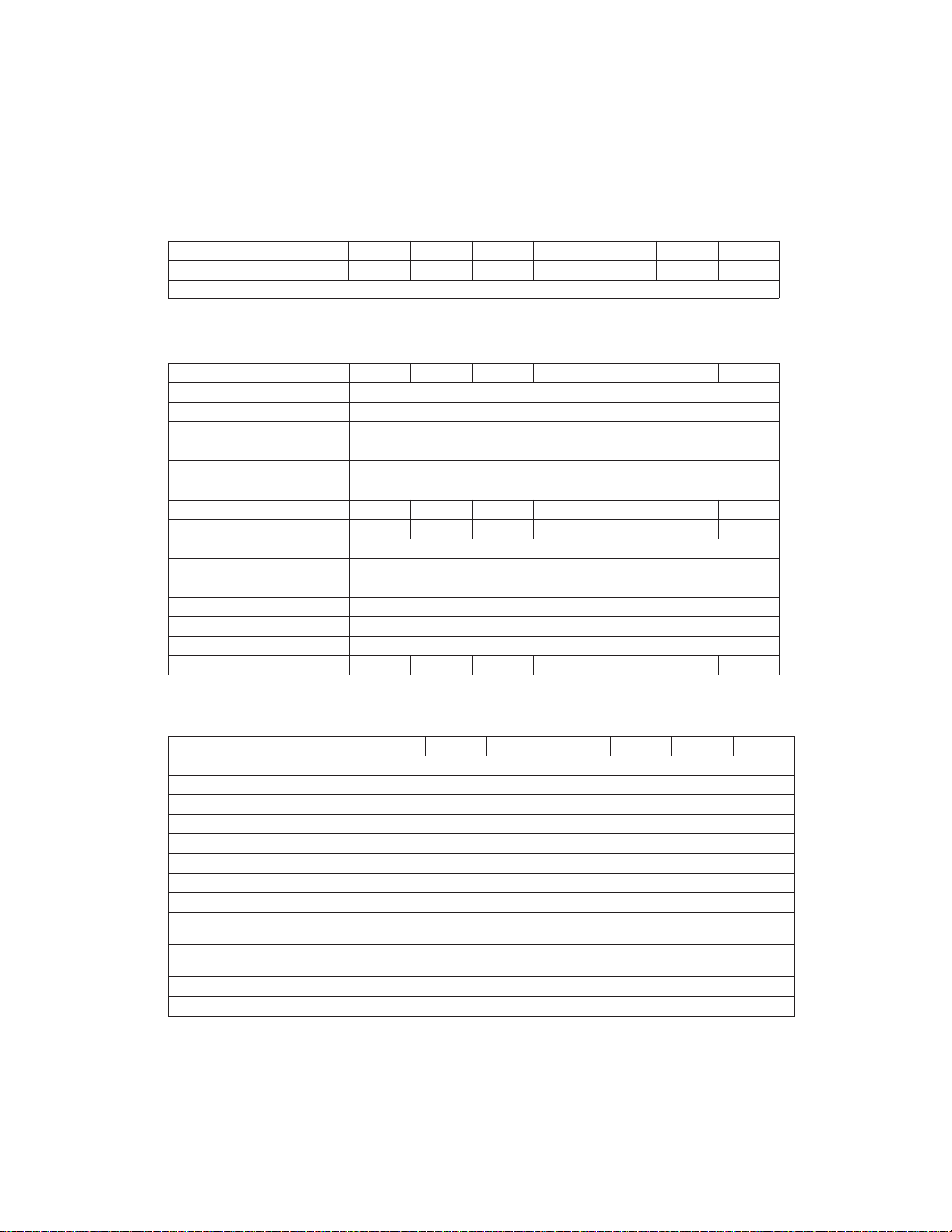
Sector Address Translation
All DiamondMax 4320 drives feature a universal translate mode. In an AT/EISA-class system, the drive may
be configured to any specified combination of cylinders, heads and sectors (within the range of the drive's
formatted capacity). DiamondMax 4320 drives power-up in a translate mode:
LEDOMLYCDHTPSenoZLmocPWABLXAMYTICAPAC
8D82719384,336136)*()*(468,057,33BM082,71
7D21519892,926136)*()*(483,235,92BM021,51
6D30319942,526136)*()*(299,054,52BM030,31
5D08019829,026136)*()*(424,590,12BM008,01
4D54809383,616136)*()*(460,415,61BM554,8
3D84609655,216136)*()*(844,656,21BM084,6
2D23409473,86136)*()*(299,044,8BM023,4
(*) The fields LZone (Landing Zone) and WPcom (Write Pre-comp) are not used by the Maxtor hard drive
and the values may be either 0 or the values set by the BIOS. All capacities listed in the above table are based
on 10
6
or one million bytes.

PRODUCT DESCRIPTION
2 – 3
Logical Block Addressing
The Logical Block Address (LBA) mode can only be utilized in systems that support this form of translation.
The cylinder, head and sector geometry of the drive, as presented to the host, differs from the actual physical
geometry. The host AT computer may access a drive of set parameters: number of cylinders, heads and
sectors per track, plus cylinder, head and sector addresses. However, the drive can’t use these host parameters
directly because of zoned recording techniques. The drive translates the host parameters to a set of logical
internal addresses for data access.
The host drive geometry parameters are mapped into an LBA based on this formula:
LBA = (HSCA - 1) + HHDA x HSPT + HNHD x HSPT x HCYA (1)
= (HSCA - 1) + HSPT x (HHDA + HNHD x HCYA) (2)
where HSCA = Host Sector Address, HHDA = Host Head Address
HCYA = Host Cylinder Address, HNHD = Host Number of Heads
HSPT = Host Sectors per Track
The LBA is checked for violating the drive capacity. If it does not, the LBA is converted to physical drive
cylinder, head and sector values. The physical address is then used to access or store the data on the disk and
for other drive related operations.
Defect Management Zone (DMZ)
Each drive model has a fixed number of spare sectors per drive, all of which are located at the end of the
drive. Upon detection of a bad sector that has been reassigned, the next sequential sector is used.
For example, if sector 3 is flagged, data that would have been stored there is “pushed down” and recorded
in sector 4. Sector 4 then effectively becomes sector 3, as sequential sectors are “pushed down” across the
entire drive. The first spare sector makes up for the loss of sector 3, and so maintains the sequential order of
data. This push down method assures maximum performance.
On-the-Fly Hardware Error Correction Code (ECC)
33 bits, single burst, guaranteed
Software ECC Correction
81 bits, single burst, guaranteed
33 bits, double bursts, guaranteed
Automatic Park and Lock Operation
Immediately following power down, dynamic braking of the spinning disks delays momentarily allowing the
read/write heads to move to an inner mechanical stop. A small fixed magnet holds the rotary actuator in
place as the disk spins down. The rotary actuator is released only when power is again applied.

PRODUCT DESCRIPTION
2 – 4
Cache Management
Buffer Segmentation
The data buffer is organized into two segments: the data buffer and the micro controller scratch pad.
The data buffer is dynamically allocated for read and write data depending on the commands received.
A variable number of read and write buffers may exist at the same time.
Read-Ahead Mode
Normally, this mode is active. Following a read request, disk read-ahead begins on the first sector and
continues sequentially until the allocated buffer is full. If a read request is received during the read-ahead
operation, the buffer is examined to determine if the request is in the cache. If a cache hit occurs, read-
ahead mode continues without interruption and the host transfer begins immediately.
Automatic Write Reallocation (AWR)
This feature is part of the write cache and reduces the risk of data loss during deferred write operations. If a
disk error occurs during the disk write process, the disk task stops and the suspect sector is reallocated to a
pool of alternate sectors located at the end of the drive. Following reallocation, the disk write task continues
until it is complete.
Write Cache Stacking
Normally, this mode is active. Write cache mode accepts the host write data into the buffer until the buffer
is full or the host transfer is complete. A command complete interrupt is generated at the end of the transfer.
A disk write task begins to store the host data to disk. Host write commands continue to be accepted and
data transferred to the buffer until either the write command stack is full or the data buffer is full. The drive
may reorder write commands to optimize drive throughput.

PRODUCT DESCRIPTION
2 – 5
Major HDA Components
Drive Mechanism
A brush-less DC direct drive motor rotates the spindle at 5,400 RPM (±0.1%). The dynamically balanced
motor/spindle assembly ensures minimal mechanical run-out to the disks. A dynamic brake provides a fast
stop to the spindle motor upon power removal. The speed tolerance includes motor performance and motor
circuit tolerances.
Rotary Actuator
All DiamondMax™ 4320 drives employ a rotary voice coil actuator which consists of a moving coil, an
actuator arm assembly and stationary magnets. The actuator moves on a low-mass, low-friction center shaft.
The low friction contributes to fast access times and low power consumption.
Read/Write Electronics
An integrated circuit mounted within the sealed head disk assembly (near the read/write heads) provides up
to eight head selection (depending on the model), read pre-amplification and write drive circuitry.
Read/Write Heads and Media
Low mass, low force magneto-resistive read/write heads record data on 3.5-inch diameter disks. Maxtor uses
a sputtered thin film medium on all disks for DiamondMax 4320 drives.
Air Filtration System
All DiamondMax 4320 drives are assembled in a Class 100 controlled environment. Over the life of the drive,
a 0.1 micron filter and breather filter located within the sealed head disk assembly (HDA) maintain a clean
environment to the heads and disks. DiamondMax 4320 drives are designed to operate in a typical office
environment with minimum environmental control.
Microprocessor
The microprocessor controls the following functions for the drive electronics:
Command execution
Cache management
Data correction and error recovery
Diagnostic execution
Data sequencing
Head positioning (including error recovery)
Host interface
Index detection
Spin speed control
Seeks
Servo
S.M.A.R.T.
PRODUCT DESCRIPTION
2 – 6
NOITARUGIFNOCREPMUJ05J84J64J44J24J
evalS/retsaM
*metsysevirdelgnisnievirdylnO
*metsysevirdlaudnievirdretsaM
metsysevirdlaudnievirdevalS
C
C
O
tceleSelbaC
*delbasiD
delbanE
O
C
noitatimiLrednilyC2904
*delbasiD
delbanE
O
C
devreseRyrotcaFO
devreseRyrotcaF O
desolC=CtluafeD=*yeK
)dellatsnirepmuj(
nepO=O
)dellatsnirepmujon(
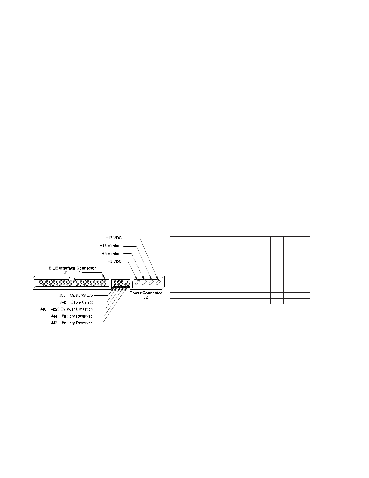
Figure 2-1
PCBA Jumper Location and Configuration
4092 Cylinder Limitation
On some older BIOS', primarily those that auto-configure the disk drive, a hang may occur when the drive
cylinder value exceeds 4096. The 4092 Cylinder Limitation jumper reduces the capacity in the Identify Drive to
4092 allowing large capacity drives to work with older BIOS'. A software driver is required to access the full
capacity of the drive.
Subsystem Configuration
Dual Drive Support
Two drives may be accessed via a common interface cable, using the same range of I/O addresses. The drives
are jumpered as device 0 or 1 (Master/Slave), and are selected by the drive select bit in the
Device/Head register of the task file.
All Task File registers are written in parallel to both drives. The interface processor on each drive decides
whether a command written to it should be executed; this depends on the type of command and which
drive is selected. Only the drive selected executes the command and activates the data bus in response to
host I/O reads; the drive not selected remains inactive.
A master/slave relationship exists between the two drives: device 0 is the master and device 1 the slave.
When J50 is closed (factory default, figure 2-1), the drive assumes the role of master; when open, the drive
acts as a slave. In single drive configurations, J50 must be closed.
Cable Select Option
CSEL (cable select) is an optional feature per ANSI ATA specification. Drives configured in a multiple drive
system are identified by CSEL’s value:
– If CSEL is grounded, then the drive address is 0.
– If CSEL is open, then the drive address is 1.
Jumper Location/Configuration
Darkened jumper pins indicate factory-installed (default) shunts.
PRODUCT SPECIFICATIONS
3 – 1
SECTION 3
Product Specifications
Models and Capacities
Performance Specifications
LEDOM8D827197D215196D303195D080194D548093D846092D23409
ecafretnI/rellortnoCdetargetnI AMDartlU/4-ATA
dohteMgnidocnE 71/61LLR4RPE
evaelretnI 1:1
metsySovreS deddebmE
epyT/eziSreffuBSBK652:sledoMksiD-2dna-1MARDMARDSBK215:sledoMksiD-4dna-3/
ecafruSrepsenoZataD 61
sdaeH/secafruSataD8765432
sksiDforebmuN4433221
ytisneDlaerA001,3ni/bM
2
ecafruSrepskcarT )srednilyC( 13, 592
ytisneDkcarT 000,31ipt
ytisneDgnidroceR 732-681ipbk
kcolB/rotceSrepsetyB 215
kcarTrepsrotceS320 3-48
evirDrepsrotceS
468,057,33483,235,92299,054,52424,590,12460,415,61844,656,21299,044,8
LEDOM8D827197D2151919
303
6D5D080194D548093D846092D23409
semiTkeeS )lacipyt(
kcarT-ot-kcarT
sm9.0
egarevA
sm0.9
mumixaM sm02<
ycnetaLegarevA sm55.5
deepSlanoitatoR )%1.0±( MPR004,5
daehrevOrellortnoC sm5.0<
etaRrefsnarTataD
ecafretnImorf/oT
)2edoM-AMDartlU(
ces/BM0.33otpu
ecafretnImorf/oT
)2edoM-AMDdrow-itluM/4OIP(
ces/BM7.61otpu
aideMmorf/oT
ces/BM0.22otpu
emiTtratS )ydaeRevirDot0( lacipytces8.8<
Drive Configuration
LEDOM
8D827197D215196D303195D080194D548093D846092D23409
yticapaCdettamroF
)edoMABLBM(
082,71021,51030,31008,01554,8084,6023,4
01saetybagemenosenifedrotxaM
6
01saetybagigenodnasetybnoillimenoro
9
.setybnoillibenoro
PRODUCT SPECIFICATIONS
3 – 2
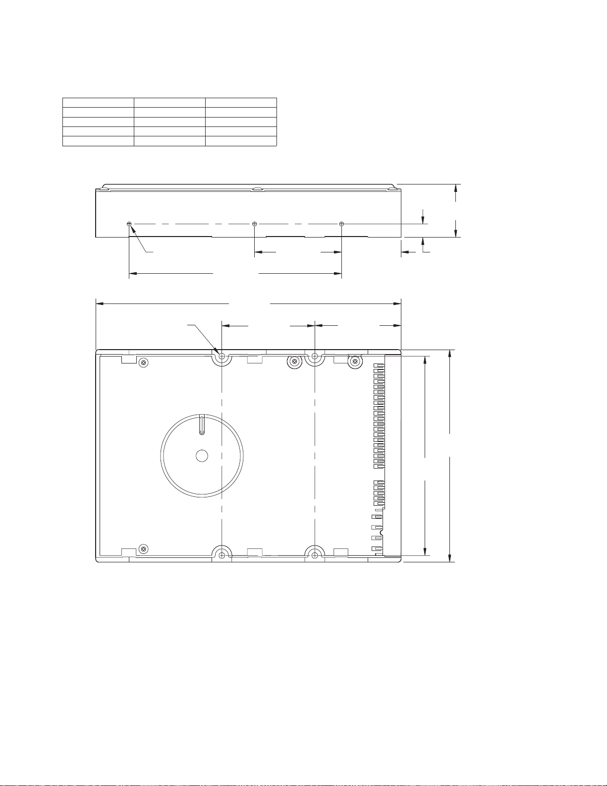
Physical Dimensions
1.028 max
[25.9 mm]
.25 ± .01
1.122 ± .02
[28.4 mm]
1.638 ± .005
[41.61 mm]
1.625 ± .02
4.000 ± .01
[101.6 mm]
1.75 ± .02
5.787 max
[146.6 mm]
6 x 6-32
UNC Tap
4 x 6-32
UNC Tap
4.00 ± .01
[102.1 mm]
3.75 ± .01
[95.25 mm]
Figure 3 - 1
Outline and Mounting Dimensions
RETEMARAPDRADNATSCIRTEM
thgieHhcni20.1sretemillim9.52
htgneLsehcni77.5sretemillim6.641
htdiWsehcni20.4sretemillim1.201
thgieWsdnuop3.1smargolik95.0
PRODUCT SPECIFICATIONS
3 – 3
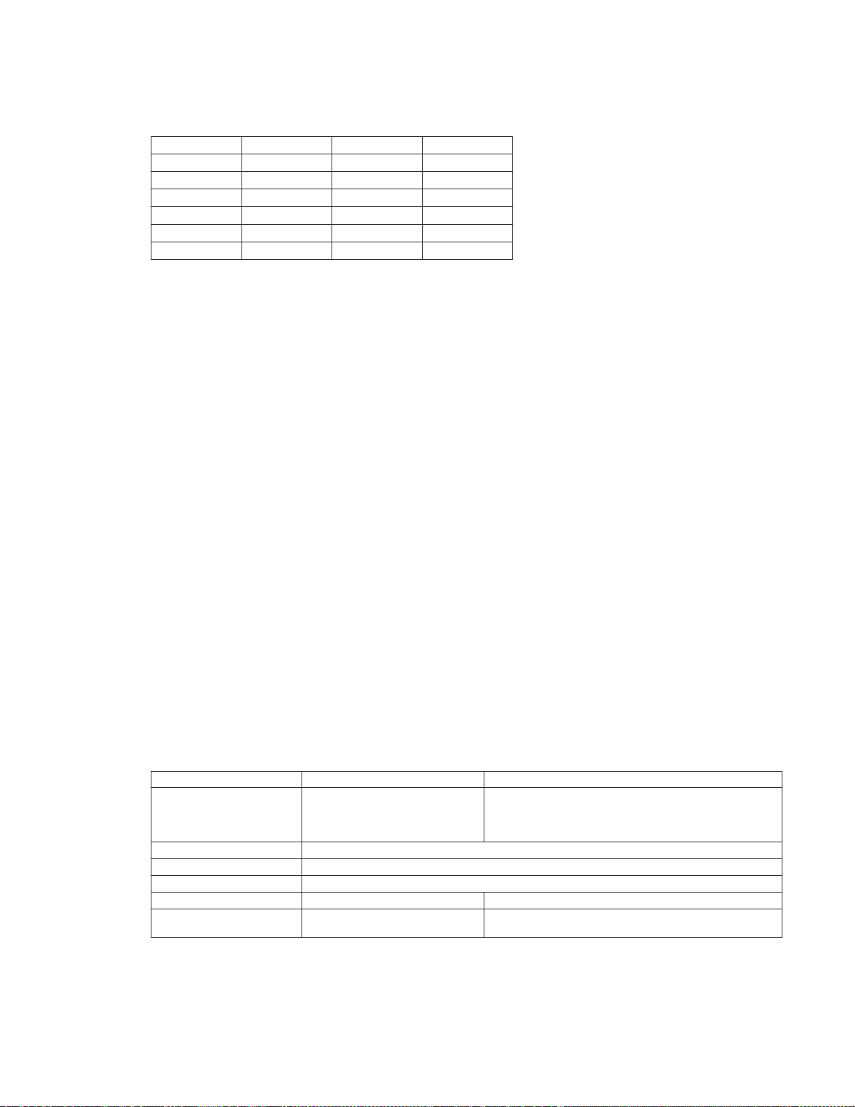
Power Requirements (Average)
Power Mode Definitions
Spin-up
The drive is spinning up following initial application of power and has not yet reached full speed.
Seek
A random access operation by the disk drive.
Read/Write
Data is being read from or written to the drive.
Idle
The drive is spinning, the actuator is parked and powered off and all other circuitry is powered on.
The drive is capable of responding to read commands within 40 ms.
Standby
The spin motor is not spinning. The drive will leave this mode upon receipt of a command that requires
disk access. The time-out value for this mode is programmable. The buffer is active to accept write data.
Sleep
This is the lowest power state – with the interface set to inactive. A software or hardware reset is required
to return the drive to the Standby state.
EPA Energy Star Compliance
Maxtor Corporation supports the goals of the U.S. Environmental Protection Agency’s Energy Star program
to reduce the electrical power consumption of computer equipment.
Environmental Limits
RETEMARAPGNITAREPOEGAROTS/GNITAREPO-NON
erutarepmeTC°55otC°5)C°04-(erutarepmetwol
,3.105dohtem,E018-DTS-LIMrep)C°17(erutarepmethgih
.snoitidnocdecudni-toh;yrogetaccitamilc
tneidarGlamrehT (ruohrepC°52)mumixam
ytidimuHevitaleR %59ot%5gnisnednoc-non()
bluBteW 72°C )mumixam(
edutitlAteef000,01ot002-teef000,04ot002-
esioNcitsuocA)edomeldI(rewopdnuosegarevaABd53
)enohporcim01,9777OSIrep(
EDOM%5±V21%5±V5REWOP
pu-nipS)kaep(Am0761Am033W7.12
keeSAm076Am053W8.9
etirW/daeRAm032Am024W9.4
eldIAm042Am052W1.4
ybdnatSAm61Am051W9.0
peelSAm41Am05W4.0

PRODUCT SPECIFICATIONS
3 – 4
Reliability Specifications
AFR
< 1.7% The annualized average failure rate (AFR) applies to the period prior
to the expiration of component design life, and is based on failures
chargeable to Maxtor.
MTBF
> 500,000 hours Maxtor does not differentiate between various usage profiles (e.g.,
power-on hours, power saving modes, non-operating periods or
operating temperatures within the published specification.)
Quality Acceptance Rate
TBD (< 1,500 DPPM) The quality acceptance rate indicates the percentage of Maxtor
products successfully installed by our customers, and/or the number
of defective parts per million (DPPM) encountered during the entire
installation process.
Start/Stop Cycles
50,000 (minimum) This indicates the minimum cycles for reliable start/stop function at a
≥ 60% confidence level.
Data Reliability
< 1 per 10
14
bits read Data errors (non-recoverable). Average data error rate allowed with all
error recovery features activated.
Component Design Life
5 years (minimum) Component design life is defined as a.) the time period before
identified wear-out mechanisms impact the failure rate, or b.) the time
period up to the wear-out point when useful component life expires.
Shock and Vibration
RETEMARAPGNITAREPOGNITAREPO-NON
kcohSlacinahceMsrorreon,sm0.2,sG02 egamadon,sm0.2,sG002
kcohSlanoitatoR egamadon,ces/ces/daR000,51
noitarbiVmodnaRG400.0tazH54-01
2
zH/
G800.0tazH26-84
2
zH/
G400.0tazH003-56
2
zH/
G6000.0tazH005-103
2
zH/
srorreon
egamadon,smrG51.2tazH000,2-01
noitarbiVeniStpewS
zH02-5
zH003-12
edutilpmaelbuodsehcni940.0
)kaep-0(edutilpmakaepG0.1

PRODUCT SPECIFICATIONS
3 – 5
EMC/EMI
Radiated Electromagnetic Field Emissions - EMC Compliance
The hard disk drive mechanism is designed as a subassembly for installation into a suitable enclosure and is
therefore not subject to Subpart J of Part 15 of FCC Rules (47CFR15) or the Canadian Department of
Communications Radio Interference Regulations. Although not required, the disk mechanism has been
tested within a suitable end-use product and found to comply with Class B limits of the FCC Rules and
Regulations of the Canadian Department of Communications.
The CE Marking indicates conformity with the European Union Low Voltage Directive (73/23/EEC) when
the disk mechanism is installed in a typical personal computer. Maxtor recommends that testing and analysis
for EMC compliance be performed with the disk mechanism installed within the user's end-use application.
Canadian Emissions Statement
This digital apparatus does not exceed the Class B limits for radio noise emissions from digital apparatus as set
out in the radio interference regulations of the Canadian department of communications.
Le present appareil numerique n'emet pas de bruit radioelectriques depassant les limites applicables aux
appareils numeriques de Class B prescrites dans le reglement sur le brouillage radioelectrique edicte par le
ministere des communications du Canada.
Safety Regulatory Compliance
All Maxtor hard drives comply with relevant product safety standards such as CE, CUL, TUV and UL rules and
regulations. As delivered, Maxtor hard drives are designed for system integration before they are used.
 Loading...