


 Loading...
Model ST7001 User Guide
FM / AM Tuner
CAUTION |
RISK OF ELECTRIC SHOCK |
DO NOT OPEN |
CAUTION: TO REDUCE THE RISK OF ELECTRIC SHOCK, |
DO NOT REMOVE COVER (OR BACK) |
NO USER-SERVICEABLE PARTS INSIDE |
REFER SERVICING TO QUALIFIED SERVICE PERSONNEL |
The lightning flash with arrowhead symbol within an equilateral triangle is intended to alert the user to the presence of uninsulated “dangerous voltage” within the product’s enclosure that may be of sufficient magnitude to constitute a risk of electric shock to persons.
The exclamation point within an equilateral triangle is intended to alert the user to the presence of important operating and maintenance (servicing) instructions in the literature accompanying the product.
WARNING
TO REDUCE THE RISK OF FIRE OR ELECTRIC SHOCK, DO NOT EXPOSE THIS PRODUCT TO RAIN OR MOISTURE.
CAUTION: TO PREVENT ELECTRIC SHOCK, MATCH WIDE BLADE OF PLUG TO WIDE SLOT, FULLY INSERT.
ATTENTION: POUR ÉVITER LES CHOC ÉLECTRIQUES, INTRODUIRE LA LAME LA PLUS LARGE DE LA FICHE DANS LA BORNE CORRESPONDANTE DE LA PRISE ET POUSSER JUSQU’AU FOND.
NOTE:
This equipment has been tested and found to comply with the limits for a Class B digital device, pursuant to Part 15 of the FCC Rules. These limits are designed to provide reasonable protection against harmful interference in a residential installation. This equipment generates, uses and can radiate radio frequency energy and, if not installed and used in accordance with the instructions, may cause harmful interference to radio communications. However, there is no guarantee that interference will not occur in a particular installation. If this equipment does cause harmful interference to radio or television reception, which can be determined by tuning the equipment off and on, the user is encouraged to try to correct the interference by one or more of the following measures:
-Reorient or relocate the receiving antenna.
-Increase the separation between the equipment and receiver.
-Connect the equipment into an outlet on a circuit different from that to which the receiver is connected.
-Consult the dealer or an experienced radio/TV technician for help.
NOTE:
Changes or modifications not expressly approved by the party responsible for compliance could void the user’s authority to operate the equipment.
NOTE TO CATV SYSTEM INSTALLER:
This reminder is provided to call the CATV (Cable-TV) system installer’s attention to Section 820-40 of the NEC which provides guidelines for proper grounding and, in particular, specifies that the cable ground shall be connected to the grounding system of the building, as close to the point of cable entry as practical.
IMPORTANT SAFETY
INSTRUCTIONS
READ BEFORE OPERATING EQUIPMENT
This product was designed and manufactured to meet strict quality and safety standards. There are, however, some installation and operation precautions which you should be particularly aware of.
1.Read Instructions – All the safety and operating instructions should be read before the product is operated.
2.Retain Instructions – The safety and operating instructions should be retained for future reference.
3.Heed Warnings – All warnings on the product and in the operating instructions should be adhered to.
4.Follow Instructions – All operating and use instructions should be followed.
5.Cleaning – Unplug this product from the wall outlet before cleaning. Do not use liquid cleaners or aerosol cleaners. Use a damp cloth for cleaning.
6.Attachments – Do not use attachments not recommended by the product manufacturer as they may cause hazards.
7.Water and Moisture – Do not use this product near water-for example, near a bath tub, wash bowl, kitchen sink, or laundry tub, in a wet basement, or near a swimming pool, and the like.
8.Accessories – Do not place this product on an unstable cart, stand, tripod, bracket, or table. The product may fall, causing serious injury to a child or adult, and serious damage to the product. Use only with a cart, stand, tripod, bracket, or table recommended by the manufacturer, or sold with the product. Any mounting of the product should follow the manufacturer’s instructions, and should use a mounting accessory recommended by the manufacturer.
9.A product and cart combination should be moved with care. Quick stops, excessive force, and uneven surfaces may cause the product and cart combination to overturn.
10.Ventilation – Slots and openings in the cabinet are provided for ventilation and to ensure reliable operation of the product and to protect it from overheating, and these openings must not be blocked or covered. The openings should never be blocked by placing the product on a bed, sofa, rug, or other similar surface. This product should not be placed in a built-in installation such as a bookcase or rack unless proper ventilation is provided or the manufacturer’s instructions have been adhered to.
11.Power Sources – This product should be operated only from the type of power source indicated on the marking label. If you are not sure of the type of power supply to your home, consult your product dealer or local power company. For products intended to operate from battery power, or other sources, refer to the operating instructions.
12.Grounding or Polarization – This product may be equipped with a polarized alternating-current line plug (a plug having one blade wider than the other). This plug will fit into the power outlet only one way. This is a safety feature. If you are unable to insert the plug fully into the outlet, try reversing the plug. If the plug should still fail to fit, contact your electrician to replace your obsolete outlet. Do not defeat the safety purpose of the polarized plug.
AC POLARIZED PLUG
13.Mains Cord Protection – Mains cord should be routed so that they are not likely to be walked on or pinched by items placed upon or against them, paying particular attention to cords at plugs, convenience receptacles, and the point where they exit from the product.
14.Protective Attachment Plug – The product is equipped with an attachment plug having overload protection. This is a safety feature. See Instruction Manual for replacement or resetting of protective device. If replacement of the plug is required, be sure the service technician has used a replacement plug specified by the manufacturer that has the same overload protection as the original plug.
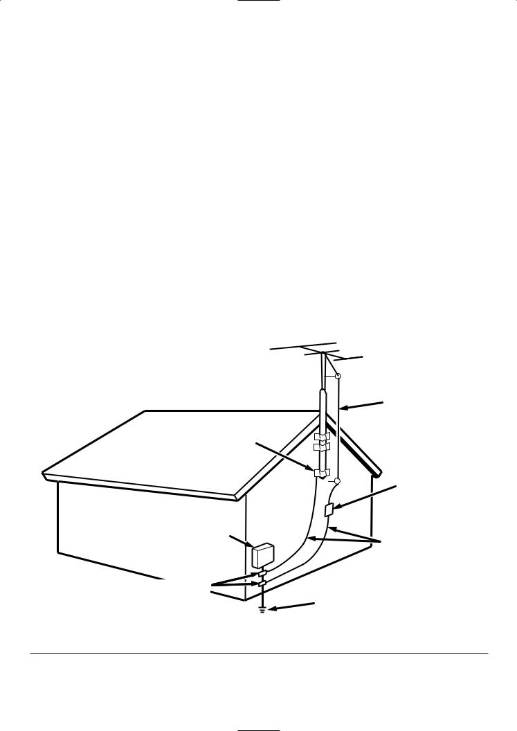
15.Outdoor Antenna Grounding – If an outside antenna or cable system is connected to the product, be sure the antenna or cable system is grounded so as to provide some protection against voltage surges and built-up static charges. Article 810 of the National Electrical Code, ANSI/NFPA 70, provides information with regard to proper grounding of the mast and supporting structure, grounding of the lead-in wire to an antenna discharge unit, size of grounding conductors, location of antenna-discharge unit, connection to grounding electrodes, and requirements for the grounding electrode. See Figure 1.
16.Lightning – For added protection for this product during a lightning storm, or when it is left unattended and unused for long periods of time, unplug it from the wall outlet and disconnect the antenna or cable system. This will prevent damage to the product due to lightning and power-line surges.
17.Power Lines – An outside antenna system should not be located in the vicinity of overhead power lines or other electric light or power circuits, or where it can fall into such power lines or circuits. When installing an outside antenna system, extreme care should be taken to keep from touching such power lines or circuits as contact with them might be fatal.
18.Overloading – Do not overload wall outlets, extension cords, or integral convenience receptacles as this can result in a risk of fire or electric shock.
19.Object and Liquid Entry – Never push objects of any kind into this product through openings as they may touch dangerous voltage points or short-out parts that could result in a fire or electric shock. Never spill liquid of any kind on the product.
20.Servicing – Do not attempt to service this product yourself as opening or removing covers may expose you to dangerous voltage or other hazards. Refer all servicing to qualified service personnel.
21.Damage Requiring Service – Unplug this product from the wall outlet and refer servicing to qualified service personnel under the following conditions:
a.When the Mains cord or plug is damaged.
b.If liquid has been spilled, or objects have fallen into the product.
c.If the product has been exposed to rain or water.
d.If the product does not operate normally by following the operating instructions. Adjust only those controls that are covered by the operating instructions as an improper adjustment of other controls may result in damage and will often require extensive work by a qualified technician to restore the product to its normal operation.
e.If the product has been dropped or damaged in any way, and
22.Replacement Parts – When replacement parts are required, be sure the service technician has used replacement parts specified by the manufacturer or have the same characteristics as the original part. Unauthorized substitutions may result in fire, electric shock, or other hazards.
23.Safety Check – Upon completion of any service or repairs to this product, ask the service technician to perform safety checks to determine that the product is in proper operating condition.
24.Wall or Ceiling Mounting – The product should be mounted to a wall or ceiling only as recommended by the manufacturer.
25.Heat – The product should be situated away from heat sources such as radiators, heat registers, stoves, or other products (including amplifiers) that produce heat.
f.When the product exhibits a distinct change in performance – this indicates a need for service.
FIGURE 1
EXAMPLE OF ANTENNA GROUNDING AS PER
NATIONAL ELECTRICAL CODE, ANSI/NFPA 70
ANTENNA
LEAD IN
WIRE
GROUND
CLAMP
ANTENNA DISCHARGE UNIT (NEC SECTION 810-20)
ELECTRIC |
GROUNDING CONDUCTORS |
|
SERVICE |
||
(NEC SECTION 810-21) |
||
EQUIPMENT |
||
|
GROUND CLAMPS
POWER SERVICE GROUNDING ELECTRODE SYSTEM
(NEC ART 250, PART H)
NEC - NATIONAL ELECTRICAL CODE
This Class B digital apparatus complies with Canadian ICES-003.
Cet appareil numérique de la Classe B est conforme à la norme NMB-003 du Canada.
CONTENTS
.............................................................................................................................................1
.........................................................................................................................................2
..........................................................................................................4
..................................................................................................................................................4
.....................................................................................................................................................5
................................................................................................................................6
......................................................................................................................................8
....................................................................................................8
.......................................................................................................................9
.........................................................................................................................................10
....................................................................................................................................10
..........................................................................................................14
...............................................................................................................................................17
...........................................................................................................................19
....................................................................................................................................19
........................................................................................................................................20
............................................................................................................................22
.............................................................................................22
..........................................................................................................................23
..............................................................................24
......................25
ENGLISH
FEATURES
• |
XM Satellite Radio Ready |
|
• |
High Performance D/A Converter |
|
• |
200 Channels, Group Presets |
The XM name and related logos are registered trademarks |
|
|
of XM Satellite Radio Inc. |
•Customizable Station Names
•Weekly Timer Program
•Sleep Timer
•Display Dimmer
•Timer-controlled AC outlet
•RS-232C Terminal for Custom Installation
1

BEFORE USE
This section must be read before any connection is made to the mains supply.
7 EQUIPMENT MAINS WORKING
SETTING
Your Marantz product has been prepared to comply with the household power and safety requirements that exist in your area.
ST7001 can be powered by 120V AC only.
7 COPYRIGHT
Recording and playback of any material may require consent. For further information refer to the following:
-Copyright Act 1956
-Dramatic and Musical Performers Act 1958
-Performers Protection Acts 1963 and 1972
-Any subsequent statutory enactments and orders
7 Do Not Locate in the Following
Places
To ensure long-lasting use, do not locate the ST7001 where:
•Exposed to direct sunlight.
•Near to sources of heat such as heaters.
•Highly humid or poorly ventilated.
•Dusty.
•Subjected to mechanical vibrations.
•On wobbly, inclined or otherwise unstable surfaces
•Radiated heat is blocked such as in cramped audio racks.
To ensure proper heat radiation, ensure the below clearance from walls and other equipment.
Left |
Above |
Right |
|
0.1 m (4 inches) or more |
0.1 m (4 inches) or more |
||
0.1 m (4 inches) or more |
|||
|
|
Rear 0.1 m (4 inches) or more
•Noise or disturbance tends to occur particularly when using indoor antennas or 300 Ω/ohms feeder wires. We recommend using outdoor antennas and 75 Ω/ohms coaxial cables.
Note
For heat dispersal, do not install this equipment in a confined space such as a book case or similar unit.
7 Accessories Check
Before use, check the below accessories were included in the package.
•Audio connecting cord x 1
•Mains cord x 1
•Remote control unit (RC7001ST) x 1
•Size “AAA” batteries x 2
•AM loop antenna x 1
•FM indoor antenna x 1
• FM antenna adaptor x 1
Noise or disturbance of the picture may be generated if this unit or any other electronic equipment using microprocessors is used near a tuner or TV.
If this happens, take the following steps:
•Install this unit as far as possible from the tuner or TV.
•Set the antenna wires from the tuner or TV away from this unit’s mains cord and input/output connection cords.
•Remote Control Connecting Cord x 1
•User Guide x 1
•Warranty Card for USA x 1
•Warranty Card for CANADA x 1
2
BEFORE USE
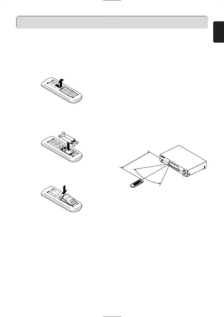
7 Loading batteries
Before using the supplied remote control unit for the first time, load the batteries in the remote control unit. The batteries provided are used to verify the operations of the remote control unit only.
1.Take hold of the tab on the battery cover which is found on the back side of the remote control unit, and pull it up.
2.Take load the two new size “AAA” batteries inside the battery compartment while taking care to align their polarities correctly with the polarity markings (ª with ª and · with ·).
Size “AAA” (SUM-4) batteries x 2
3.Push the battery cover down in the direction of the arrow to close it.
Notes on batteries:
•Replace the batteries with new ones if the set does not operate even when the remote control unit is operated nearby the set. (The included battery is only for verifying operation.)
•To prevent damage or leakage of battery fluid:
-Do not use a new battery together with an old one.
-Do not use two different types of batteries.
-Do not short-circuit, disassemble, heat or dispose of batteries in flames.
•If the battery fluid should leak, carefully wipe the fluid off the inside of the battery compartment and insert new batteries.
7 |
Operating range of the remote |
ENGLISH |
|
control unit
•Point the remote control unit at the remote sensor on the main unit as shown on the diagram.
•The remote control unit can be used from a straight distance of approximately 5 meters from the main unit, but this distance will be shorter if there are obstacles in the way or if the remote control unit is not pointed directly at the remote sensor.
•The remote control unit can be operated at a horizontal angle of up to 30 degrees with respect to the remote sensor.
Note
•It may be difficult to operate the remote control unit if the remote sensor is exposed to direct sunlight or strong artificial light.
•Do not press buttons on the main unit and remote control unit simultaneously. Doing so may result in malfunction.
•Neon signs or other devices emitting pulse-type noise nearby may result in malfunction, so keep the set as far away from such devices as possible.
Approx. 5m
60˚
3
PART NAMES AND FUNCTIONS
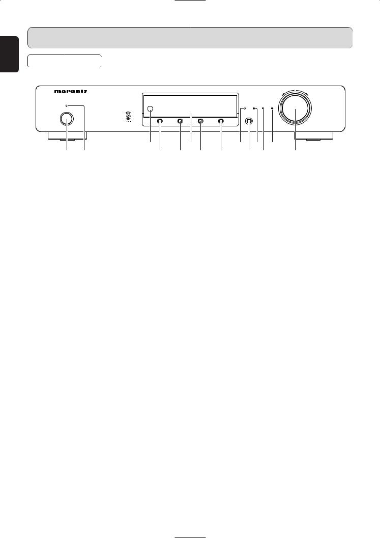
FRONT PANEL
For details on the functions of these parts, refer to the pages given in parenthesis.
TUNING/PRESET
FM/AM TUNER ST7001
STANDBY
SLEEP |
TIMER |
TUNED |
STEREO |
POWER ON/STANDBY
|
CATEGORY |
DISPLAY |
MENU |
A—PRESET |
BAND SELECT |
|
|
|
|
|
PUSH ENTER |
|
e |
|
y |
|
o !1 !3 |
q w |
r |
t |
u |
i |
!0!2 !4 |
q Power ON/STANDBY switch
This is used to turn the unit’s power ON and STANDBY. When it is pressed, the display lights and the power is turned on; when it is pressed again, the power is turned off and STANDBY indicator will be illuminated.
w STANDBY indicator
This indicator illuminates red when the unit’s status is standby.
e Remote control sensor
This sensor receives the infrared light transmitted from the wireless remote control unit.
For remote control, point the wireless remote control unit to the sensor.
Some of the functions can be operated with the remote control unit (RC7001ST).
!1TIMER indicator
This indicator illuminates while the timer program is ON.
Timer Program
When a recording device with an auto start recording function is connected (power on) to the AC outlet on the rear panel of this tuner, timer recording is can be controlled by the tuner’s timer.
Note
•For setting procedures for recording device, see the instruction manual that came with the recording device.
•If the internal clock has not been set, set the time first before using the timer program. ( page 19)
!2TUNED indicator
This indicator illuminates when a station is properly tuned in.
r CATEGORY button
This button to ENTER/EXIT XM Category search mode. Available only when the unit is in the XM Satelite Radio mode.
!3STEREO indicator
This indicator illuminates when an FM station is being tuned into stereo condition.
t DISPLAY button
This button is used to switch XM information such as artist name/song title, category or signal status.
Available only when the unit in the XM Satelite Radio mode.
y Display
u MENU button
This button to ENTER/EXIT menu mode.
The unit times out if no operation is performed for about 5 seconds after the menu mode is set.
i A–PRESET button
This button is used for the auto preset memory feature which automatically searches for and sets radio stations.
o SLEEP indicator
This indicator illuminates while the sleep timer is running. The display is automatically dimmed while the sleep timer is running.
!0BAND SELECT button
This button is used to select XM, FM or AM.
!4TUNING/PRESET knob
This knob is used in conjunction with the MENU button, and is used to select and determine the operation mode. Also, this knob is used for the TUNING/PRESET search. In the tuning mode, the reception frequency is tuned up or down. Turning the control in the clockwise direction tunes the frequency up. Tuning the control in the counterclockwise direction tunes the reception frequency down.
In the preset mode, the selection of the preset channel is moved up or down. The auto tuning operation cannot be used when in this mode.
When entering station names, use this control to select the letters ( page 13).
Memo
•Whenever the Power ON/STANDBY switch is in the STANDBY position, the unit is still connected on AC line voltage.
Please be sure to unplug the cord when you leave home for, say, a vacation.
•Noise may be generated if a near-by television set is on during AM, FM or XM broadcasting reception. The tuner should be used as far away from a television as possible.
•Effective period of memory back-up is about a month under normal temperature.
4
PART NAMES AND FUNCTIONS
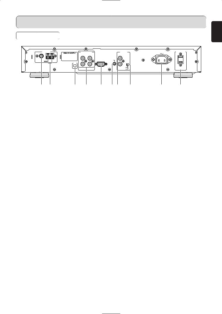
REAR PANEL
ANTENNA |
ANALOG OUT |
REMOTE |
AC IN |
AC OUTLET |
|
|
1 |
2 |
CONTROL |
|
|
MODEL NO. ST7001 |
|
|
|
||
L |
|
L |
IN |
|
|
FM(75Ω) GND AM |
|
RS-232C |
FLASHER |
|
|
|
|
|
IN |
|
|
XM |
|
R |
OUT |
|
|
R |
|
|
|
||
|
|
|
EXTERNAL |
|
SWITCHED |
|
|
|
INTERNAL |
|
100W MAX |
ENGLISH
a b |
c d e fg h |
i j |
a FM antenna terminal (75 ohms)
Connect an external FM antenna with a coaxial cable, or the supplied FM indoor antenna.
b AM antenna and ground terminals
Connect the supplied AM loop antenna. Use the terminals marked “AM” and “GND”. The supplied AM loop antenna will provide good AM reception in most areas. Position the loop antenna until you hear the best reception.
c XM terminal
See page 14 for connecting information.
h EXTERNAL/INTERNAL switch
Before the unit was shipped from the factory, this switch was set to INTERNAL to enable the remote sensor built into the unit to be used.
Before using the supplied connecting cord to make the connection between the unit and the remote control connectors on a Marantz equipment, set the switch to EXTERNAL.
Note
•Signals cannot be received from the remote control unit if the switch is kept at EXTERNAL when the unit is to be used on its own.
d ANALOG OUT 1, 2 (analog output) connectors
The audio signals are output from these connectors.
i AC INLET
Plug the supplied mains cord into this AC INLET and then into the power outlet on the wall.
ST7001 can be powered by 120V AC only.
e RS-232C
The RS-232C port is to be used in conjunction with an external controller to control the operation of the ST7001 by using an external device.
f FLASHER IN (Flasher input terminal)
This terminal is to control the unit from another zone. Connect the control signal from a Keypad, etc.
g REMOTE CONTROL IN and OUT connectors
Using the supplied remote control connecting cord, these connectors enable this unit to be connected to a Marantz component equipped with remote control connectors. These connections make it possible to control an entire system that centers on the amplifier or other such component.
j AC OUTLET
Connect the AC mains cord of components such as a MD or Tape Deck to this outlet. This SWITCHED outlet provides power only when the ST7001 is turned on.
Caution
•In order to avoid potential turn-off thumps, anything plugged into this outlet should be powered up before the ST7001 is turned on.
•The capacity of this AC outlet is 100W. Do not connect devices that consume electricity more than the capacity of this AC outlet.
5
PART NAMES AND FUNCTIONS
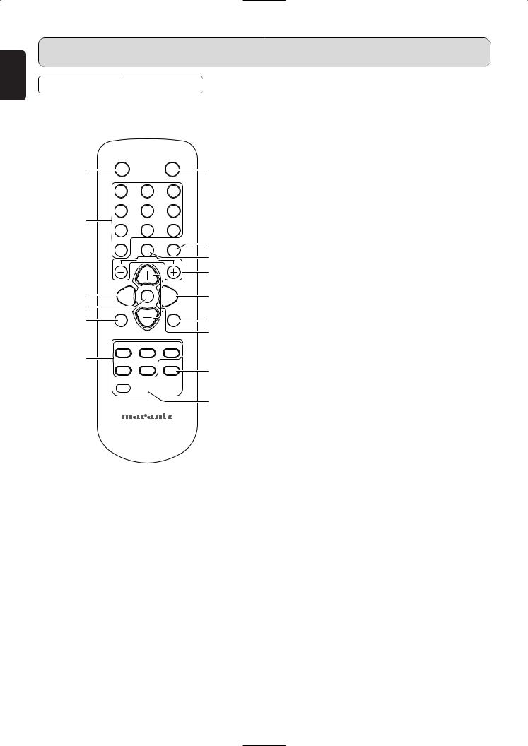
REMOTE CONTROL UNIT
For details on the functions of these parts, refer to the pages given in parenthesis ( page 10 ~ 22).
|
STANDBY |
|
|
ON |
|
z |
|
|
|
|
, |
|
1 |
|
2 |
3 |
|
|
4 |
|
5 |
6 |
|
x |
|
|
|
|
|
|
7 |
|
8 |
9 |
|
|
|
DIMMER |
DISPLAY |
. |
|
|
10 |
|
|
|
|
|
|
|
|
⁄0 |
|
|
|
TUNING |
|
||
|
|
|
|
|
⁄1 |
|
|
NTE |
|
|
|
c |
|
E |
R |
|
⁄2 |
BAND |
|
|
MENU |
||
v |
A-PRESET |
|
|
SHIFT |
|
|
/A-TUNE |
|
|
|
|
b |
|
|
|
|
⁄3 |
|
|
CHANNEL/ |
|
⁄4 |
|
|
|
CONTROL |
|
||
|
A/B |
|
C/D |
E/F |
|
n |
G/H |
|
I/J |
T-MODE |
|
⁄5
SLEEP TIMER MEMO
m

 ⁄6 ⁄7
⁄6 ⁄7
REMOTE CONTROLLER
RC7001ST
z STANDBY button
Press this button to switch from the operating mode to the standby mode.
x Preset channel buttons (1 ~ 10)
Use these when presenting and recalling stations. Also use these with the SHIFT ,MEMORY GROUP button to use a total of 200 preset channels (FM/AM 100 , XM 100), A (1 ~ 10), B (1 ~ 10), ... J (1 ~ 10).
c BAND button
This button is used to select XM, FM or AM.
v ENTER button
This button is used to set the menu.
b A-PRESET/A-TUNE button
When pressed in the FM mode, receivable FM/AM stations are automatically stored in the preset memory in order starting from preset channel A1.
n MEMORY GROUP buttons (A/B, C/D, E/F,
G/H, I/J)
Use these buttons to switch the preset channel’s shift mode directly.
m SLEEP button
This button is used for setting the sleep timer. ( page 22)
, ON button
Press this button to switch from the standby mode to the operating mode.
. DISPLAY button
This button is used to switch XM information such as artist name/song title, category or signal status. Available only when the unit in the XM Satelite Radio mode.
⁄0DIMMER button
The display’s brightness switches (in three levels) each time this button is pressed.
⁄1TUNING buttons
Use these to change the received frequency/XM channel to a higher frequency/XM channel (+) or a lower frequency/XM channel (–).
⁄2MENU button
This button is used to enter/exit menu mode.
⁄3SHIFT button
Use this button to select the memory groups, A (1 ~ 10), B (1 ~ 10), ... J (1 ~ 10).
⁄4CHANNEL/CONTROL button
This button is used to select radio presets or select stations and menu options.
⁄5T-MODE button
Selects the stereo mode or mono mode when a FM stereo broadcast is received. ( page 10)
⁄6MEMO button
Frequencies and station names can be stored in the memory. When this button is pressed, the Preset channel number on the display flashes for 10 seconds. Use the SHIFT button and the Preset channel buttons during this time to designate the desired preset channel.
⁄7TIMER button
This button is used to enter the timer program mode. Clock setup mode can be entered by holding down this button for 3 seconds or more. Please refer to page 20 for TIMER program operation.
6
Loading...