


SR8500

Model SR7500/SR8500 User Guide
AV Surround Receiver

ENGLISH
WARRANTY
For warranty information, contact your local Marantz
distributor.
RETAIN YOUR PURCHASE RECEIPT
Your purchase receipt is your permanent record of a
valuable purchase. It should be kept in a safe place to
be referred to as necessary for insurance purposes
or when corresponding with Marantz.
IMPORTANT
When seeking warranty service, it is the responsibility
of the consumer to establish proof and date of
purchase. Your purchase receipt or invoice is
adequate for such proof.
FOR U.K. ONLY
This undertaking is in addition to a consumer's
statutory rights and does not affect those rights in
any way.
FRANÇAIS
GARANTIE
Pour des informations sur la garantie, contacter le
distributeur local Marantz.
CONSERVER L'ATTESTATION D'ACHAT
L'attestation d'achat est la preuve permanente
d'un achat de valeur. La conserver en lieu sur pour
s'y reporter aux fins d'obtention d'une couverture
d'assurance ou dans le cadre de correspondances
avec Marantz.
IMPORTANT
Pour l'obtention d'un service couvert par la
garantie, il incombe au client d'établir la preuve de
l'achat et d'en corroborer la date. Le reçu ou la
facture constituent des preuves suffisantes.
DEUTSCH
GARANTIE
Bei Garantiefragen wenden Sie sich bitte an Ihren
Marantz-Händler.
HEBEN SIE IHRE QUITTING GUT AUF
Die Quittung dient Ihnen als bleibende Unterlage
für Ihren wertvollen Einkauf Das Aufbewahren der
Quittung ist wichtig, da die darin enthaltenen
Angaben für Versicherungswecke oder bei
Korrespondenz mit Marantz angeführt werden
müssen.
WICHTIG!
Bei Garantiefragen muß der Kunde eine
Kaufunterlage mit Kaufdatum vorlegen. Ihren
Quittung oder Rechnung ist als Unterlage
ausreichend.
NEDERLANDS
GARANTIE
Voor inlichtingen omtrent garantie dient u zich tot
uw plaatselijke Marantz.
UW KWITANTIE, KASSABON E.D. BEWAREN
Uw kwitantie, kassabon e.d. vormen uw bewijs van
aankoop van een waardevol artikel en dienen op
een veilige plaats bewaard te worden voor evt,
verwijzing bijv, in verbend met verzekering of bij
correspondentie met Marantz.
BELANGRIJK
Bij een evt, beroep op de garantie is het de
verantwoordelijkheid van de consument een
gedateerd bewijs van aankoop te tonen. Uw
kassabon of factuurzijn voldoende bewijs.
ESPAÑOL
GARANTIA
Para obtener información acerca de la garantia
póngase en contacto con su distribuidor Marantz.
GUARDE SU RECIBO DE COMPRA
Su recibo de compra es su prueba permanente de
haber adquirido un aparato de valor, Este recibo
deberá guardarlo en un lugar seguro y utilizarlo
como referencia cuando tenga que hacer uso del
seguro o se ponga en contacto con Marantz.
IMPORTANTE
Cuando solicite el servicio otorgado por la garantia
el usuario tiene la responsabilidad de demonstrar
cuándo efectuó la compra. En este caso, su recibo
de compra será la prueba apropiada.
ITALIANO
GARANZIA
L’apparecchio è coperto da una garanzia di buon
funzionamento della durata di un anno, o del
periodo previsto dalla legge, a partire dalla data di
acquisto comprovata da un documento attestante
il nominativo del Rivenditore e la data di vendita.
La garanzia sarà prestata con la sostituzione o la
riparazione gratuita delle parti difettose.
Non sono coperti da garanzia difetti derivanti da
uso improprio, errata installazione, manutenzione
effettuata da personale non autorizzato o,
comunque, da circostanze che non possano
riferirsi a difetti di funzionamento dell’apparecchio.
Sono inoltre esclusi dalla garanzia gli interventi
inerenti l’installazione e l’allacciamento agli
impianti di alimentazione.
Gli apparecchi verranno riparati presso i nostri
Centri di Assistenza Autorizzati. Le spese ed i
rischi di trasporto sono a carico del cliente.
La casa costruttrice declina ogni responsabilità per
danni diretti o indiretti provocati dalla inosservanza
delle prescrizioni di installazione, uso e manutenzione
dettagliate nel presente manuale o per guasti dovuti
ad uso continuato a fini professionali.
PORTUGUÊS
GARANTIA
Para informações sobre a garantia, contactar o
distribuidor Marantz local.
GUARDAR O RECIBO DE COMPRA
O recibo é o registo permanente da compra que fez.
Deve ser guardado num local seguro, para ser
apresentado em questões relacionadas com o
seguro ou para quando tiver de contactar a Marantz.
IMPORTANTE
Quando procurar assisténcia técnica ao abrigo da
garantia, é da responsabilidade do consumidor
estabelecer a prova e data de compra. O recibe é
prova adequada.
SVENSKA
GARANTI
För information om garantin, kontakta Marantz
lokalagent.
SPAR KVITTOT
Kvittot är ett inköpsbevis på en värdefull vara. Det
skall förvaras säkert och hänvisas till vid
försäkringsfall eller vidkorrespondens mod
Marantz.
VIKTIGT
Fö att garantin skall gälla är det kundens sak att
framställa bevis och datum om köpet. Kvitto eller
faktura är tillräokligt bevis fö detta.
DANSK
GARANTI
Henvend dem til Deres MARANTZ-forhandler
angående inrformation om garantien.
GEM DERES KVITTERING
Deres købskvittering er Deres varige bevis på et
dyrt køb. Den bør gemmes godt og anvendes som
bevis, hvis De vil tegne en forsikring, eller hvis De
kommunikerer med Marantz.
VIGTIGT
Det påhviler forbrugeren at skaffe bevis for købet og
købsdatoen, hvis han eller hun ønsker garantiservice.
Deres købskvittering eller faktura er et fuldgyldigt
bevis herpå.

CE MARKING
English
The SR7500/SR8500 is in conformity with the EMC directive and low-voltage directive.
Français
Le SR7500/SR8500 est conforme à la directive EMC et à la directive sur les basses
tensions.
Deutsch
Das Modell SR7500/SR8500 entspricht den EMC-Richtlinien und den Richtlinien für
Niederspannungsgeräte.
Nederlands
De SR7500/SR8500 voldoet aan de EMC eisen en de vereisten voor laag-voltage.
Español
El SR7500/SR8500 está de acuerdo con las normas EMC y las relacionadas con baja
tensión.
Italiano
Il SR7500/SR8500 è conforme alle direttive CEE ed a quelle per i bassi voltaggi.
Português
O SR7500/SR8500 conforma com as diretrizes EMC e de baixa voltagem.
Svenska
SR7500/SR8500 är tillverkad i enlighet med EMC direktiven och direktiven för
lågvoltsutrusning.
Dansk
Model SR7500/SR8500 er i overensstemmelse med EMC-direktiveet og direktivet om
lavspænding.
English
WARNINGS
-
Do not expose the equipment to rain or moisture.
- Do not remove the cover from the equipment.
-
Do not insert anything into the equipment through
the ventilation holes.
- Do not handle the mains lead with wet hands.
-
Do not cover the ventilation with any items such as
tablecloths, newspapers, curtains, etc.
-
No naked flame sources, such as lighted candles,
should be placed on the equipment.
-
When disposing of used batteries, please comply
with governmental regulations or environmental
public instruction’s rules that apply in your
country or area.
-
Do not place anything about 0.2 meter above the
top panel.
-
Make a space of about 0.2 meter around the unit.
Français
AVERTISSEMENTS
- Ne pas exposer l’appareil à la pluie ni à l’humi-
dité.
- Ne pas essayer de retirer le boîtier de l’appareil.
- Ne rien insérer dans l’appareil par les orifices de
ventilation.
- Ne pas manipuler le cordon d’alimentation avec
les mains mouillées.
- Ne pas recouvrir les ouïes de ventilation avec un
objet quelconque comme une nappe, un journal,
un rideau, etc.
- Ne placer aucune source de flamme nue,
comme une bougie allumée, sur l'appareil.
- Pour mettre au rebut les piles usées, respecter
les lois gouvernementales ou les règlements
officiels concernant l’environnement qui
s'appliquent à votre pays ou région.
- Ne placez aucun object à moins de 0,2 mètre
environ du panneau supérieur.
- Veiller à ce qu’aucun objet ne soit à moins de
0,2 mètre des côtés de l'appareil.
Deutsch
WARNHINWEISE
- Das Gerät nicht Regen oder Feuchtigkeit
aussetzen.
- Die Abdeckung nicht vom Gerät abnehmen.
- Keine Gegenstände durch die Belüftungs-
schlitze stecken.
- Das Netzkabel nicht mit feuchten oder nassen
Händen anfassen.
- Decken Sie die Lüftungsöffnungen nicht mit
einem Tischtuch, einer Zeitung, einem Vorhang
usw. ab.
- Es dürfen keine Gegenstände mit offener
Flamme, wie etwa brennende Kerzen, auf dem
Gerät aufgestellt werden.
- Beachten Sie bei der Entsorgung der verbrauch-
ten Batterien alle geltenden lokalen und überre-
gionalen Regelungen.
- Darauf achten, daß über dem Gerät ein Frei-
raum von mindestens 0.2 meter vorhanden ist.
- Auf allen Geräteseiten muß ein Zwischenraum
von ungefähr 0,2 meter vorhanden sein.
Nederlands
WAARSCHUWINGEN
- Stel het apparaat niet bloot aan regen of vocht.
- Verwijder de afdekplaat van het apparaat niet.
- Duw niets door de ventilatieopeningen in het
apparaat.
- Raak het netsnoer niet met natte handen aan.
- Bedek de ventilatieopeningen niet met enige
voorwerpen, zoals tafelkleden, kranten,
gordijnen, enz.
- Plaats geen brandende voorwerpen, zoals
kaarsen, op het apparaat.
- Volg bij het weggooien van verbruikte batterijen
de overheidswetgeving of milieuvoorschriften op
die van kracht zijn in het land of de regio waarin
u zich bevindt.
- Zorg dat er tenminste 0.2 meter vrije ruimte
boven het toestel is.
- Zorg dat er 0,2 meter vrije ruimte rond het
toestel is.

Español
ADVERTENCIAS
-
No exponga el equipo a la lluvia ni a la humedad.
- No extraiga la tapa del equipo.
- No introduzca nada en el interior del equipo a
través de los orificios de ventilación.
- No maneje el cable de alimentación con las
manos mojadas.
- No cubra la ventilación con objetos como man-
teles, periódicos, cortinas, etc.
- No deben colocarse sobre el equipo elementos
con fuego, por ejemplo velas encendidas.
- Cuando se eliminen baterías usadas, deben
cumplirse las reglamentaciones oficiales o las
normas de protección medioambiental aplica-
bles en su país o en su zona.
- No ponga nada a menos de 0.2 metro por
encima del panel superior.
- Deje un espacio de unos 0,2 metro alrededor de
la unidad.
Italiano
AVVERTENZE
- Non esporre l’apparecchio alla pioggia o all’umi-
dità.
- Non rimuovere il coperchio dell’apparecchio.
- Non introdurre oggetti all’interno dell’apparec-
chio attraverso i fori di ventilazione.
- Non toccare il cavo di alimentazione con le mani
bagnate.
- Non coprire le fessure di ventilazione con
tovaglie, giornali, tende od oggetti analoghi.
- Non posare sull'apparecchio sorgenti di fiamme
scoperte quali candele accese.
- Smaltire le pile usate in conformità alle norme
governative o disposizioni ambientali vigenti nel
proprio paese o zona.
- Non posare alcun oggetto sopra il pannello
superiore, lasciando libero uno spazio di circa
0,2 m.
- Lasciare 0,2 metro liberi tutto intorno l'unità.
Português
ADVERTÊNCIAS
-Não exponha o equipamento à chuva nem à
humidade.
-Não retire a tampa do equipamento.
-Não atire nada para dentro do equipamento
através dos orificíos de ventilação.
-Não manuseie o cabo de alimentação com as
mãos molhadas.
-Não cobrir os orifícios de ventilação com objec-
tos tais como toalhas de mesa, jornais, cortinas,
etc.
-Não colocar chamas abertas tais como velas
acesas, sobre o aparelho.
- Ao deitar foras as pilhas usadas, favor observar
os regulamentos governamentais ou as regras
com respeito ao meio ambiente que se aplicam
no seu país ou área de residência.
- Deixar um espaço completamente livre de cerca
de 0.2 metro acima do painel superior.
- Deixar um espaço de cerca de 0,2 metro ao
redor do aparelho.
Svenska
VARNINGAR
- Utsätt inte utrustningen för regn eller fukt.
- Ta inte bort utrustningens hölje.
-
För inte in föremål i utrustningen genom ventilations-
hålen.
- Hantera inte nätsladden med våta händer.
-Täck inte för ventilationsöppningarna med några
föremål som till exempel bordsdukar, dagstid-
ningar, gardiner e.d.
- Inga föremål med öppen låga, som till exempel
tända stearinljus, bör placeras på utrustningen.
-Följ de lagar och miljöskyddsråd som gäller i det
land eller område där du bor när du gör dig av
med batterier.
- Placera inte någonting närmare än 0.2 meter
ovanför apparaten eller enheten.
- Se till att det finns omkring 0,2 meter fri plats
runt omkring enheten.
Dansk
ADVARSLER
- Udsæt ikke udstyret for regn eller fugt.
- Fjern ikke dækslet fra udstyret.
- Stik ikke noget ind i udstyret gennem ventilations-
hullerne.
-Rør ikke ved netledningen med våde hænder.
- Tildæk ikke ventilationsåbningerne med ting
som duge, aviser, gardiner og lignende.
- Kilder til åben ild, som for eksempel tændte
sterarinlys, må ikke anbringes på apparatet.
-Når du skiller dig af med gamle batterier, bedes
du gøre dette i overensstemmelse med de love,
regler og miljømæssige forskrifter, som er
gældende i dit land eller område.
- Anbring ikke noget nærmere end 0.2 m over
apparatets overside,
-Sørg for, at der er et frit område på omkring 0,2
m omkring apparatet.
1
ENGLISH
TABLE OF CONTENTS FOREWORD
This section must be read before any connection is
made to the mains supply.
This user guide covers the SR7500 and
SR8500, though the SR7500 is given for the
title. Explanations of features belonging
only to the SR8500 are indicated as “SR8500
only”.
EQUIPMENT MAINS WORKING
SETTING
Your Marantz product has been prepared to
comply with the household power and safety
requirements that exist in your area.
SR7500 can be powered by 230V AC only.
COPYRIGHT
Recording and playback of any material may
require consent. For further information refer to the
following:
— Copyright Act 1956
— Dramatic and Musical Performers Act 1958
— Performers Protection Acts 1963 and 1972
— Any subsequent statutory enactments and
orders
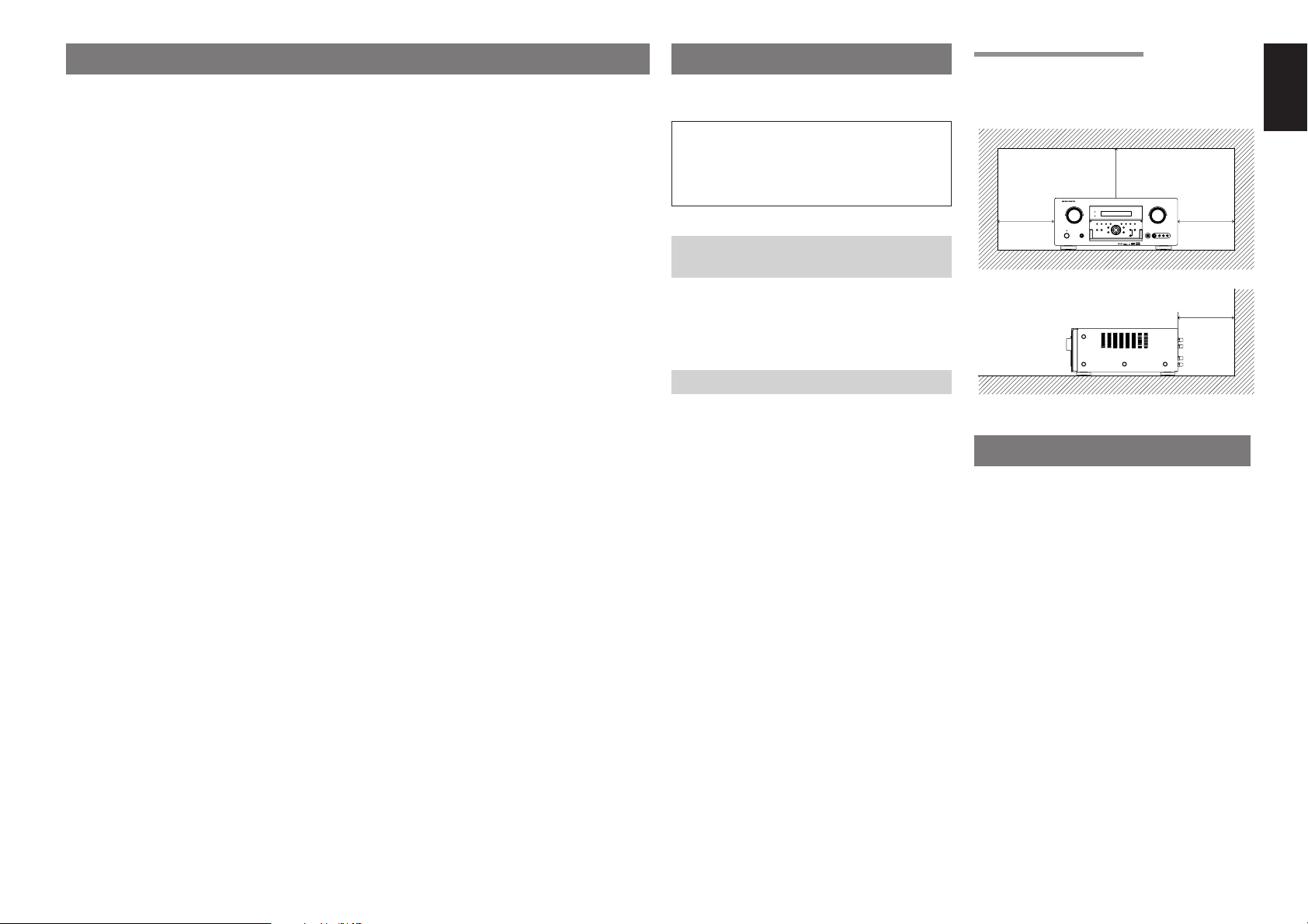
CAUTIONS ON INSTALLATION
For heat dispersal, leave at least 20 cm/8 inch of
space between the top, back and sides of this unit
and the wall or other components.
• Do not obstruct the ventilation holes.
INTRODUCTION
Thank you for purchasing the Marantz SR7500
Surround receiver.
This remarkable component has been engineered
to provide you with many years of home theater
enjoyment. Please take a few minutes to read this
manual thoroughly before you connect and
operate the SR7500.
As there are a number of connection and
configuration options, you are encouraged to
discuss your own particular home theater setup
with your Marantz A/V specialist dealer.
FOREWORD ........................................ 1
EQUIPMENT MAINS WORKING SETTING .................... 1
COPYRIGHT ................................................................... 1
INTRODUCTION.................................. 1
DESCRIPTION..................................... 2
FEATURES .......................................... 4
ACCESSORIES ................................... 4
FRONT PANEL .................................... 5
FL DISPLAY AND INDICATER ........................................ 6
REAR PANEL ...................................... 7
REMOTE CONTROLLER RC8500SR..
8
NAMES AND FUNCTIONS .............................................. 8
LCD INDICATORS ...........................................................9
REMOTE CONTROL RANGE ....................................... 10
LOADING BATTERIES .................................................. 10
BATTERY REPLACEMENT INTERVAL ........................ 10
SETTING THE TIME ..................................................... 10
GENERAL INFORMATION OF RC8500SR
TO SR7500 ............................................................... 11
CONNECTIONS................................. 12
SPEAKER PLACEMENT ............................................... 12
CONNECTING SPEAKERS .......................................... 12
CONNECTING AUDIO COMPONENTS ........................ 13
CONNECTING VIDEO COMPONENTS ........................ 14
ADVANCED CONNECTING .......................................... 15
CONNECTING THE REMOTE CONTROL JACKS ....... 15
CONNECTING THE ANTENNA TERMINALS ............... 16
CONNECTING FOR THE MULTI ROOM ...................... 17
SETUP ............................................... 18
ON SCREEN DISPLAY MENU SYSTEM ...................... 18
1 INPUT SETUP
(ASSIGNABLE DIGITAL INPUT) ............................... 19
2 SPEAKER SETUP ..................................................... 19
3 PREFERENCE .......................................................... 22
4 PL
II
(PRO LOGIC
II
) MUSIC PARAMETER ............ 22
5 CS
II
(CIRCLE SURROUND
II
) PARAMETER ........ 22
6 MULTI ROOM ............................................................ 23
7 7.1 CH INPUT LEVEL ................................................ 23
8 DC TRIGGER SETUP ............................................... 23
BASIC OPERATION (PLAY BACK) .. 24
SELECTING AN INPUT SOURCE ................................ 24
VIDEO CONVERT ......................................................... 24
SELECTING THE SURROUND MODE ......................... 24
ADJUSTING THE MAIN VOLUME ................................ 24
ADJUSTING THE TONE
(BASS & TREBLE) CONTROL ................................. 24
TEMPORARILY TURNING OFF THE SOUND .............. 25
USING THE SLEEP TIMER ...........................................25
NIGHT MODE ................................................................ 25
SURROUND MODE........................... 25
OTHER FUNCTION ........................... 29
TV AUTO ON/OFF FUNCTION ..................................... 29
ATTENUATION TO ANALOG INPUT SIGNAL .............. 29
LISTENING THROUGH HEADPHONES ...................... 29
DOLBY HEADPHONE MODE ....................................... 29
VIDEO ON/OFF ............................................................. 29
DISPLAY MODE ............................................................ 29
SELECTING ANALOG AUDIO INPUT
OR DIGITAL AUDIO INPUT ...................................... 30
RECORDING AN ANALOG SOURCE ........................... 30
SPEAKER A/B ............................................................... 30
7.1 CH INPUT ................................................................ 30
AUX2 INPUT .................................................................. 31
LIP.SYNC ....................................................................... 31
BASIC OPERATION (TUNER) .......... 32
LISTENING TO THE TUNER ........................................ 32
PRESET MEMORY ....................................................... 33
RDS OPERATION ......................................................... 35
MULTI ROOM SYSTEM..................... 36
MULTI ROOM PLAYBACK
USING THE MULTI ROOM OUT TERMINALS ......... 36
MULTI ROOM PLAYBACK
USING THE MULTI SPEAKER TERMINALS ............ 36
OPERATION OF THE MULTI ROOM OUTPUTS
WITH THE REMOTE CONTROL
FROM A SECOND ROOM ........................................ 36
REMOTE CONTROLLER OPERATION ..
37
CONTROLLING MARANTZ COMPONENTS ................ 37
BASIC OPERATION ...................................................... 39
PROGRAMMING MACROS .......................................... 42
CLONE MODE ............................................................... 44
SETUP ........................................................................... 45
TROUBLESHOOTING....................... 46
TECHNICAL SPECIFICATIONS ....... 47
DIMENSIONS .................................... 47
20 cm (8 ins.)
20 cm (8 ins.)
AV SURROUND RECEIVER SR5500
ENTER
2
ENGLISH
THX need not be activated for music, movies made
especially for TV, or shows such as sports
programming, talk shows, etc.
This is because they were originally mixed for a
small room environment.
THX is a trademark or registered trademark of THX
Ltd. Surround EX is a jointly developed technology
of THX and Dolby Laboratories, Inc. and is a
trademark of Dolby Laboratories, Inc. Used under
authorization. All rights reserved.
THX Surround EX—Dolby DIgital Surround EX is a
joint development of Dolby Laboratories and THX
Ltd.
In a movie theater, film soundtracks that have been
encoded with Dolby Digital Surround EX
technology are able to reproduce an extra channel
which has been added during the mixing of the
program. This channel, called Surround Back,
places sounds behind the listener in addition to the
currently available front left, front center, front
right, surround right, surround left and subwoofer
channels. This additional channel provides the
opportunity for more detailed imaging behind the
listener and brings more depth, spacious
ambience and sound localization than ever before.
Movies that were created using the Dolby Digital
Surround EX technology, when released into the
home consumer market may exhibit wording to that
effect on the packaging. A list of movies created
using this technology can be found on the Dolby
web site at www.dolby.com. A list of available
DVD software titles encoded with this technology
an be found at www.thx.com.
Only receiver and controller products bearing the
THX Surround EX logo, when in the THX Surround
EX mode, faithfully reproduce this new technology
in the home. This product may also engage the
THX Surround EX mode during the playback of 5.1
channel material that is not Dolby Digital Surround
EX eocnded. In such case, the information
delivered to the Surround Back channel will be
program dependent and may or may not be very
pleasing depending on the particular soundtrack
and the tastes of the individual listener.
“SURROUND EX™” is a trademark of Dolby
Laboratories. Used under authorization.
DTS was introduced in 1994 to provide 5.1
channels of discrete digital audio into home theater
systems.
DTS brings you premium quality discrete
multichannel digital sound to both movies and
music.
DTS is a multichannel sound system designed to
create full range digital sound reproduction.
The no compromise DTS digital process sets the
standard of quality for cinema sound by delivering
an exact copy of the studio master recordings to
neighborhood and home theaters.
Now, every moviegoer can hear the sound exactly
as the moviemaker intended.
DTS can be enjoyed in the home for either movies
or music on of DVD’s, LD’s, and CD’s.
“DTS” and “DTS Digital Surround” are registered
trademarks of Digital Theater Systems, Inc.
The advantages of discrete multichannel systems
over matrix are well known.
But even in homes equipped for discrete
multichannel, there remains a need for high-quality
matrix decoding. This is because of the large
library of matrix surround motion pictures available
on disc and on VHS tape; and analog television
broadcasts.
The typical matrix decoder of today derives a
center channel and a mono surround channel from
two-channel matrix stereo material. It is better than
a simple matrix in that it includes steering logic to
improve separation, but because of its mono,
band-limited surround it can be disappointing to
users accustomed to discrete multichannel.
Neo:6 offers several important improvements as
follow,
• Neo:6 provides up to six full-band channels of
matrix decoding from stereo matrix material.
Users with 6.1 and 5.1 systems will derive six
and five separate channels, respectively,
corresponding to the standard home-theater
speaker layouts.
• Neo:6 technology allows various sound
elements within a channel or channels to be
steered separately, and in a way which follows
naturally from the original presentation.
DESCRIPTION
THX
®
is an exclusive set of standards and
technologies established by the world-renowned
film production company, Lucasfilm Ltd. THX
resulted from George Lucas’ desire to reproduce
the movie soundtrack as faithfully as possible both
in the movie theater and in the home theater.
THX engineers developed patented technologies
to accurately translate the sound from a movie
theater environment into the home, correcting the
tonal and spatial errors that occur.
When the THX mode of the SR7500 is on, three
distinct THX technologies are automatically
added:
Re-Equalization-restores the correct tonal balance
for watching a movie in a home environment.
These sounds are otherwise mixed to be brighter
for a large movie theater. Re-EQ compensates for
this and prevents the soundtracks from being
overly bright and harsh when played in a home
theater.
Timbre Matching-filters the information going to
the surround speakers so they more closely match
the tonal characteristics of the sound coming from
the front speakers.
This ensures seamless panning between the front
and surround speakers.
Adaptive Decorrelation-slightly changes one
surround channel’s time and phase relationship
with respect to the other surround channel.
This expands the listening position and creates
with only two surround speakers the same
spacious surround experience as in a movie
theater with multiple surround speakers.
The Marantz SR7500 was required to pass a
rigorous series of quality and performance tests, in
addition to incorporating the technologies
explained above, in order to be THX certified by
Lucasfilm Ltd.
THX requirements cover every aspect of
performance including pre-amplifier and power
amplifier performance and operation, and
hundreds of other parameters in both the digital
and analog domain.
Movies which have been encoded in Dolby Digital,
DTS, Dolby Pro Logic, stereo and Mono will all
benefit from the THX mode when being viewed.
The THX mode should only be activated when
watching movies which were originally produced
for a movie theater environment.
• Neo:6 offers a music mode to expand stereo
nonmatrix recordings into the five- or six-
channel layout, in a way which does not diminish
the subtlety and integrity of the original stereo
recording.
DTS-ES Extended Surround is a new multichannel
digital signal format developed by Digital Theater
Systems Inc. While offering high compatibility with
the conventional DTS Digital Surround format,
DTS-ES Extended Surround greatly improves the
360-degree surround impression and space
expression thanks to further expanded surround
signals. This format has been used professionally
in movie theaters since 1999.
In addition to the 5.1 surround channels (FL, FR,
C, SL, SR and LFE), DTS-ES Extended Surround
also offers the SB (Surround Back) channel for
surround playback with a total of 6.1 channels.
DTS-ES Extended Surround includes two signal
formats with different surround signal recording
methods, as DTS-ES Discrete 6.1 and DTS-ES
Matrix 6.1.
“DTS”, “DTS-ES and “Neo:6” are trademarks of
Digital Theater Systems, Inc.
The stereo CD is a 16-bit medium with sampling at
44.1 kHz. Professional audio has been 20- or 24-
bit for some time, and there is increasing interest in
higher sampling rates both for recording and for
delivery into the home. Greater bit depths provide
extended dynamic range. Higher sampling rates
allow wider frequency response and the use of
anti-alias and reconstruction filters with more
favorable aural characteristics.
DTS 96/24 allows for 5.1channel sound tracks to
be encoded at a rate of 96kHz/24bits on DVD-
Video titles.
When DVD-video appeared, it became possible to
deliver 24-bit, 96 kHz audio into the home, but only
in two channels, and with serious limitations on
picture. This capability has had little use.
DVD-audio allows 96/24 in six channels, but a new
player is needed, and only analog outputs are
provided, necessitating the use of the D/A
converters and analog electronics provided in the
player.
3
ENGLISH
DTS 96/24 offers the following:
1. Sound quality transparent to the original 96/24
master.
2.Full backward compatibility with all existing
decoders. (Existing decoders will output a 48
kHz signal)
3.No new player required: DTS 96/24 can be
carried on DVD-video, or in the video zone of
DVD-audio, accessible to all DVD players.
4. 96/24 5.1-channel sound with full-quality full-
motion video, for music programs and motion
picture soundtracks on DVD-video.
“DTS” and “DTS 96/24” are trademarks of Digital
Theater Systems, Inc.
Dolby Digital identifies the use of Dolby Digital
audio coding for such consumer formats as DVD
and DTV. As with film sound, Dolby Digital can
provide up to five full-range channels for left,
center, and right screen channels, independent left
and right surround channels, and a sixth (“.1”)
channel for low-frequency effects.
Dolby Surround Pro Logic
II
is an improved matrix
decoding technology that provides better spatiality
and directionality on Dolby Surround program
material; provides a convincing three-dimensional
soundfield on conventional stereo music
recordings; and is ideally suited to bring the
surround experience to automotive sound. While
conventional surround programming is fully
compatible with Dolby Surround Pro Logic
II
decoders, soundtracks will be able to be encoded
specifically to take full advantage of Pro Logic
II
playback, including separate left and right
surround channels. (Such material is also
compatible with conventional Pro Logic decoders.)
Dolby Digital EX creates six full-bandwidth output
channels from 5.1-channel sources. This is done
using a matrix decoder that derives three surround
channels from the two in the original recording.
For best results, Dolby Digital EX should be used
with movies soundtracks recorded with Dolby
Digital Surround EX.
About Dolby Pro Logic
II
x
Dolby Pro Logic II x technology delivers a natural
and immersing 7.1-channel listening experience to
the home theater environment. A product of
Dolby's expertise in surround sound and matrix
decoding technologies, Dolby Pro Logic II x is a
complete surround sound solution that maximizes
the entertainment experience from stereo as well
as 5.1-channel encoded sources.
Dolby Pro Logic II x is fully compatible with Dolby
Surround Pro Logic technology and can optimally
decode the thousands of commercially available
Dolby Surround encoded video cassettes and
television programs with enhanced depth and
spatiality. It can also process any high-quality
stereo or Advanced Resolution 5.1-channel music
content into a seamless 6.1- or 7.1-channel
listening experience.
The Dolby Headphone technology provides a
surround sound listening experience over headphones.
When listening to multichannel content such as
DVD movies over headphones, the listening
experience is fundamentally different than
listening to speakers. Since the headphone
speaker drivers are covering the pinna of the ear,
the listening experience differs greatly from
traditional speaker playback. Dolby utilizes
patented headphone perspective curves to solve
this problem and provides a non-fatiguing,
immersive, home theater listening experience.
Dolby Headphone also delivers exceptional 3D
audio from stereo material.
Manufactured under license from Dolby
Laboratories. “Dolby”, “Pro Logic”, and the double-
D symbol are trademarks of Dolby Laboratories.
Circle Surround II (CS-II) is a powerful and
versatile multichannel technology. CS-II is
designed to enable up to 6.1 multichannel surround
sound playback from mono, stereo, CS encoded
sources and other matrix encoded sources. In all
cases the decoder extends it into 6 channels of
surround audio and a LFE/subwoofer signal. The
CS-II decoder creates a listening environment that
places the listener “inside” music performances
and dramatically improves both hi-fi audio
conventional surround-encoded video material.
CS-II provides composite stereo rear channels to
greatly improve separation and image positioning–
adding a heightened sense of realism to both audio
and A/V productions.
CS-II is packed with other useful feature like dialog
clarity (SRS Dialog) for movies and cinema-like
bass enrichment (TruBass). CS-II can enable the
dialog to become clearer and more discernable in
movies and it enables the bass frequencies
contained in the original programming to more
closely achieve low frequencies–overcoming the
low frequency limitations of the speakers by full
octave.
Circle Surround II , Dialog Clarity, TruBass, SRS
and symbol are trademarks of SRS Labs, Inc.
Circle Surround II, Dialog Clarity and TruBass
technology are incorporated under license from
SRS Labs, Inc.
(SR8500 only)
HDCD
®
(High Definition Compatible Digital
®
) is a
patented process for delivering on Compact Disc
the full richness and details of the original
microphone feed.
HDCD encoded CDs sound better because they
are encoded with 20-bits of real musical
information as compared to 16-bits for all other
CDs.
HDCD overcomes the limitation of the 16-bit CD
format by using a sophisticated system to encode
the additional four bits onto the CD while remaining
completely compatible with the CD format.
When listening to HDCD recordings, you hear
more dynamic range, a focused 3-D sound stage,
and extremely natural vocal and musical timbre.
With HDCD, you get the body, depth and emotion
of the original performance not a flat, digital
imitation.
HDCD system manufactured under license from
Microsoft. This product is covered by one or more
of the following: In the United States 5,479,168
5,638,074 5,640,161 5,808,574 5,838,274
5,854,600 5,864,311 5,872,531 and in Australia
669,114 with other patents pending.
4
ENGLISH
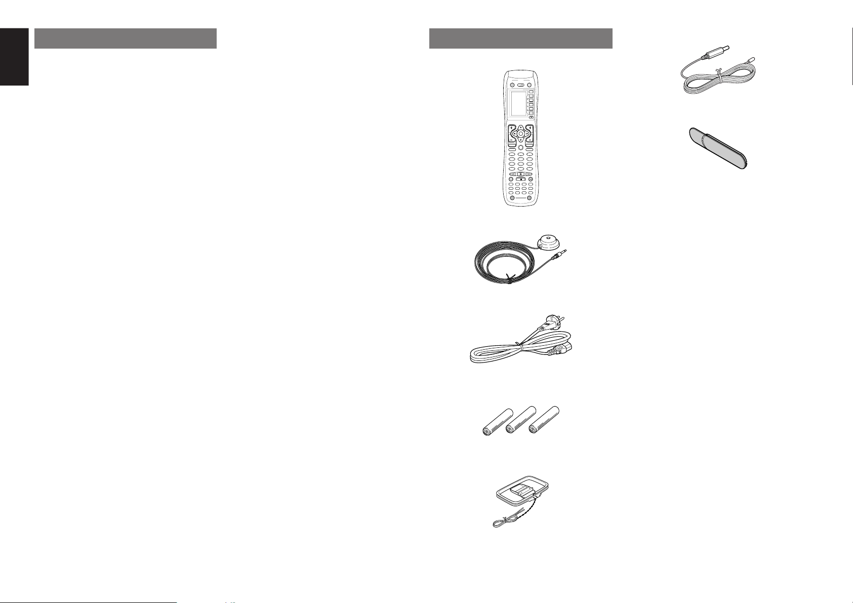
ACCESSORIES
Remote Controller RC8500SR
2 31
5 64
8
0
97
MEMO
CLEAR
DSS
AMP
AUX2
AUX1
TAPE
TUNER
CD
CD-R
MD
VCRDVD
TV
SOURCE
OFF
ON/OFF
POWER
ON
D4
D5
D2
M
D1
D3
D5
OK
VOL
CH
PREV
MUTE
MENU
EXIT
GUIDE
TEST
CH.SEL
LIP.SYNC
SURR
7.1CH
ATT
SPK-AB
DISP
OSD
THX
SLEEP
12
LIGHT
Learning Remote Controller
RC8500SR
Microphone MC-10
AC cable
AAA-size batteries
×
3
AM Loop Antenna
FEATURES
The SR7500 incorporates the latest generation of
digital surround sound decoding technology such
as Dolby Digital EX, Dolby Digital, DTS ES
(Discrete 6.1 and Matrix 6.1), DTS Neo:6 (Cinema,
Music), Dolby Pro-Logic II (Movie, Music and
Game), Dolby Pro-Logic IIx (Movie, Music and
Game), Circle Surround II (Cinema, Music and
Mono).
In addition, Marantz has focused on the future. By
utilizing pre-out jacks, 7.1 direct inputs and a RS-232C
communication port, the SR7500 is tomorrow’s
technology, today!
• THX Select certified
7ch amplifiers have enough power for even the
most difficult conditions found in large rooms.
Enormous power reserves endow the system with
substantial dynamic ability at high sound levels.
105 watts (SR7500) / 110 watts (SR8500) to each
of the 7 main channels the power amp section
features an advanced, premium high-storage
power supply capacitors, and fully discrete output
stages housed in cast aluminum heat sinks .
The SR7500 incorporates the most advanced
Digital Signal Processing circuitry, along with a
Crystal
®
192 kHz/24 bit D/A converter in each of
the 7 channels. Independent power supply circuits
are incorporated for the FL display, audio and
video sections for maximum separation, clarity
and dynamic range. Together with hand-selected
customized components, all elements work in
harmony to recreate the emotion, exactly as the
artist had intended.
The SR7500 is designed and engineered with
extensive feedback from custom installation
experts, dealers and consumers. It features multi-
room/multisource, assignable DC trigger, a RS-
232C communication port, Flasher input, heavy
duty speaker binding posts and an extensive array
of both analog and digital inputs / outputs. With 6
assignable digital inputs (7 total), 4 component
inputs, SACD Multi Channel (7.1 channel) direct
inputs video convert system and a speaker-B and
OSD output versatility is taken to a stunning new
level. Furthermore, the SR7500 can output the
OSD information through the Y/C (S-video) and
composite video outputs.
An easy-to-use programmable, learning remote
control allows full access to all of the operating
functions and can be used for system operation as
well.
The new generation of Marantz Receivers is stylish
and completely symmetrical. On the front panel of
the SR7500, buttons are kept to a minimum. Source
selectors and volume controls are intuitively placed.
The SR7500 is here to perform in your unrivaled
home entertainment setup.
• THX / THX Surround EX
• Dolby Digital EX, Dolby Digital, DTS ES
(Discrete 6.1, Matrix 6.1, Neo:6)
• Dolby Pro Logic II (Movie, Music, Game)
• Dolby Pro Logic II x (Movie, Music, Game)
• Circle Surround II (Cinema, Music, Mono)
• MRAC (Marantz Room Acoustic Calibration)
• 7 × 10⁵ Watts (8 Ohms), Discrete Amplifiers
(SR8500: 7 × 110 Watts)
• High Power Current Feedback Circuitry
• Massive Energy Power Supply, Huge EI
Transformer, Large ELCO’s.
• 192 kHz/24 bit Crystal
®
DAC for all 8 Channels
• 32 bit Digital Surround Processing Chipsets
• Video Off Mode
• Large Heavy Duty Speaker Terminals for all
Channels
• RS-232C Terminal for Future Upgrade or
System Control
•
Set Up Menu via all Video Output
(Composite, S-Video and Component video)
• Auto Input Signal Detection
• Improved Station Name Input Method, 50
Presets
• Auto Adjust Function for Speaker Distance
Settings (Delay Time)
• Front Optical AUX Input
(Digital Camera, Portable DVD)
• Assignable DC Trigger Output
• Programmable, learning remote control
• Flasher Input
• Video convert system (Composite Video ↔
S Video → Component Video)
• Assignable DVI-D INPUT (SR8500 only)
• HDCD (SR8500 only)
• Copper Plate Chassis (SR8500 only)
• Troidal Core Transformer (SR8500 only)
FM Antenna
Front AUX Jack Cover
PUSH
PUSH
User Guide
5
ENGLISH
e
HEADPHONE jack for stereo headphones
This jack may be used to listen to the SR7500’s
output through a pair of headphones. Be certain
that the headphones have a standard 1/4” stereo
phono plug. Note that the main room speakers will
automatically be turned off when the headphone
jack is in use.
Notes:
• When using headphones, the surround mode will
change to STEREO and Dolby Headphone by
MENU and Cursor button.
• The surround mode returns to the previous setting
as soon as the headphone plug is removed from
the jack.
r
SURROUND MODE button
You can select the surround mode by pressing this
button.
t
AUTO (Auto surround) button
Press this button to select the AUTO mode from
the surround modes. When this mode is selected,
the receiver determines the surround mode
corresponding to a digital input signal
automatically.
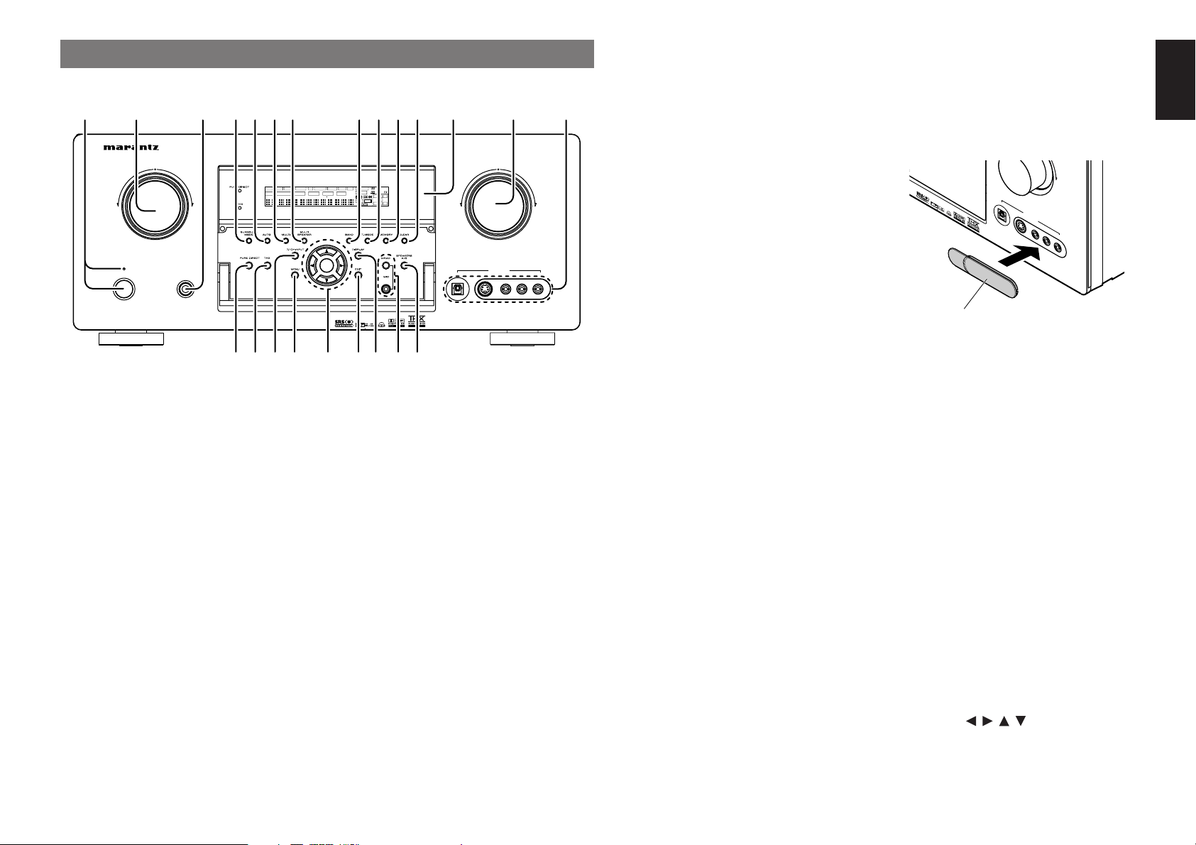
q
POWER switch and STANDBY indicator
Press the button to turn the power ON, and press
again to turn it OFF. If the POWER switch is in the
ON position, the power of this unit can be turned
ON/OFF by pressing the POWER button on the
remote control unit.
When this unit is in the standby mode with the
POWER switch set to the ON position, pressing
the ENTER button also allows to turn the power on.
The STANDBY indicator lights up when this unit is
the standby mode (power OFF) by the remote
control unit.
w
INPUT SELECTOR knob (AUDIO/ VIDEO)
This knob is used to select the input sources.
The video function selectors, such as TV, DVD,
VCR1, DSS and AUX1 select video and audio
simultaneously.
Audio function sources such as CD, TAPE, CD-R/
MD, TUNER and AUX2 may be selected in
conjunction with a Video source.
This feature (Sound Injection) combines a sound
from one source with a picture from another.
Choose the video source first, and then choose a
different audio source to activate this function.
y
MULTI (Multi Room) button
Press this button to activate the Multiroom system.
“MULTI” indicator will be illuminated in the display.
u
MULTI SPEAKER button
Press this button to activate the Multiroom Speaker
system. “MULTI” indicator will be illuminated in the
display.
(See page 36)
i
BAND button
Press this button to switch between FM and AM in
the TUNER mode.
o
T-MODE button
Press this button to select the auto stereo mode or
mono mode when the FM band is selected.
The “AUTO” indicator lights in the auto stereo
mode. (See page 32)
!0
MEMORY button
Press this button to enter the tuner preset memory
numbers or station names. (See page 33)
!1
CLEAR button
Press this button to cancel the station-memory
setting mode or preset scan tuning. (See page 33)
!2
INFRARED receiving sensor window
This window receives infrared signals for the
remote control.
!3
VOLUME control knob
Adjusts the overall sound level. Turning the control
clockwise increases the sound level.
!4
AUX1 INPUT jacks
These auxiliary video/audio input jacks accept the
connections of a camcorder, portable DVD, game
etc. When not using these jacks, protect with the
included jack covers.
How to Attach the Front AUX Jack Cover
AUX 1 IN
PU
T
AU
D
IO
S-VIDEO
DIG
ITAL V
IDE
O
L
R
U
P
PUSH
PUSH
!5
PURE DIRECT button
When this button is pressed, the tone control
circuitry is bypassed as well as Bass Management.
“PURE DIRECT” indicator will be illuminated in the
display.
Notes:
• The surround mode is automatically switched to
AUTO when the pure direct function is turned on.
• Additionally, Speaker Configurations are fixed
automatically as follows.
Front SPKR = Large, Center SPKR = Large,
Surround SPKR = Large, Sub woofer = On
!6
THX button
Press this button to select THX processing for
input source.
!7
7.1CH INPUT button
Press this button to select the output of an external
multichannel player.
!8
MENU button
This button is used to enter the SETUP MAIN
MENU.
!9
Cursor ( , , , ) / ENTER button
Use these buttons when operating the SETUP
MAIN MENU and TUNER function.
FRONT PANEL
AV SURROUND RECEIVER SR7500
POWER ON/OFF PHONES
STANDBY
L
C
R
SL S SR
LFE
DIGITAL
SURROUND
DISP MULTI AUTO TUNED ST SPKR A B V-OFF
NIGHT
PEAK ANALOG
DIGITAL
ATT
SLEEP
SURR DIRECT
AUTO
DISC 6.1 MTX 6.1
PCM
AAC
AUX 1 INPUT
AUDIOS-VIDEODIGITAL VIDEO L R
DOWN
UP
VOLUME
ENTER
INPUT SELECTOR
!8 @0 @2!9
q t yu i o !0 !1r !2 !3 !4ew
!5 !6 !7 @1 @3
Front AUX Jack Cover
6
ENGLISH
DISP MULTI AUT O TUNED ST V
–
OFF NIGHT PEAK ANALOG
DIGITAL
ATT
SLEEP
SURR
AUTO
DISC 6.1 MTX 6.1 SPKR AB
DIGITAL
SURROUND
PCM
L
C
R
SL S SR
LFE
¡6
g
s
a
¡7¡8 ¡5
h k¡0¡1 ¡3f
j l
¡2
¡4
d
¡9
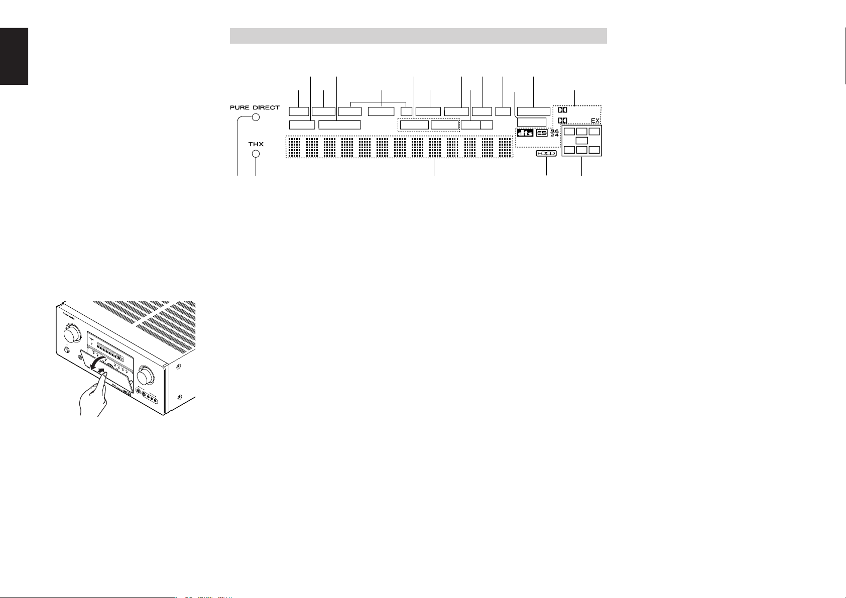
FL DISPLAY AND INDICATER
a
DISP (Display Off) indicator
This indicator is illuminated when the SR7500 is in
the display off condition.
s
SLEEP timer indicator
This indicator is illuminated when the sleep timer
function in the main-room is in use.
d
Multi-room system indicator
This indicator is illuminated when the multi-room
system is active.
f
AUTO SURR (Auto Surround mode)
indicator
This indicator is illuminated to show that the AUTO
SURROUND mode is in use.
g
TUNER’s indicators
AUTO : This indicator illuminates when the
tuner’s Auto mode is in use.
TUNED : This indicator illuminates when a
station is being received with
sufficient signal strength to provide
acceptable listening quality.
ST(Stereo) : This indicator illuminates when an
FM station is being tuned into
stereo condition.
h
DTS-ES mode indicators
(DISC6.1, MTX6.1)
These indicators will illuminate to show the DTS-
ES decoding mode (Discrete 6.1 or Matrix 6.1).
j
V (video)-OFF mode indicator
This indicator is illuminated when the Video-OFF
function is active.
k
NIGHT mode indicator
This indicator is illuminated when the SR7500 is in
the Night mode, which reduces the dynamic range
of digital program material at low volume levels.
l
SPKR (speaker) AB indicator
Active speaker system will be illuminated by this
indicator.
¡0
PEAK indicator
This indicator is a monitor for an analog audio input
signal. If the selected analog audio input signal is
greater than the capable level of internal
processing, this will illuminate. If this happens, you
should press the ATT button on the remote.
¡1
ATT (Attenuation) indicator
This indicator is illuminated when the attenuation
function is active.
¡2
DIGITAL Input Indicator
This indicator lights when a digital input has been
selected.
¡3
ANALOG input indicator
This indicator is illuminated when an analog input
source has been selected.
¡4
SIGNAL FORMAT indicators
2 DIGITAL, EX, 2 SURROUND, dts, ES, 96/24,
PCM
When the selected input is a digital source, some
of these indicators will be illuminated to display the
specific type of signal in use.
¡5
ENCODED CHANNEL STATUS indicators
These indicators display the channels that are
encoded with a digital
input signal. If the selected digital input signal is
Dolby Digital 5.1ch or DTS 5.1ch, “L”, “C”, “R”,
“SL”, “SR” and “LFE” will be illuminated.If the
digital input signal is 2 channel PCM-audio, “L” and
“R” will be displayed.
If Dolby Digital 5.1ch signal with Surround EX flag
or DTS-ES signal comes in, “L”, “C”, “R”, “SL”, “S” ,
“SR” and “LFE” will be illuminated.
¡6
Main Information Display
This display shows messages relating to the
status, input source, surround mode, tuner,
volume level or other aspects of unit’s operation.
¡7
THX indicator
This indicator illuminated when the SR7500 is in
the THX mode.
¡8
PURE DIRECT indicator
This indicator is illuminated when the SR7500 is in
the PURE DIRECT mode.
¡9
HDCD indicator (SR8500 only)
When HDCD signal is decoded, this indicator will
light up.
@0
EXIT button
This button is used to exit from the SETUP MAIN
MENU.
@1
DISPLAY button
When this button is pressed, the FL display mode
is changed as Surround Mode → Auto-display Off
→ Display Off → Input Function and the display off
indicator (DISP) lights up in condition of DISPLAY
OFF.
@2
MRAC button / MIC jack
Press to automatically measure speaker
characteristics using the included microphone
(MC-10). (See page 21)
@3
SPEAKER A/B button
Press this button to select speaker systems A and/
or B.
Opening and closing the front panel door
When you want to use the controls behind the front
panel door, open the door by gently pressing on
the lower part of the panel. Keep the door closed
when not using these controls.
AV S
URR
OUND
R
ECEIVER SR7
50
0
PHONES
S
T
A
N
D
B
Y
L
C
R
SL
S
SR
LF
E
D
IG
IT
A
L
S
U
RR
O
U
N
D
DISP
MULTI
AUTO
TUNED
ST
SPKR A B
V-OFF
NIGHT
PEAK
ANALOG
DIGITAL
ATT
SLEEP
SURR
DIRECT
AUTO
DISC 6.1
MTX 6.1
P
CM
AAC
A
U
X
1
I
N
P
U
T
A
U
D
I
O
S
-
VI
D
E
O
D
IG
IT
A
L
V
ID
E
O
L
R
E
N
T
E
R
DOW
N
UP
VOLUME
P
O
W
E
R
O
N
/O
FF
I
N
P
U
T
S
E
L
E
C
T
O
R
Notes:
• Be careful not to pinch your fingers between the
door and the panel.
7
ENGLISH
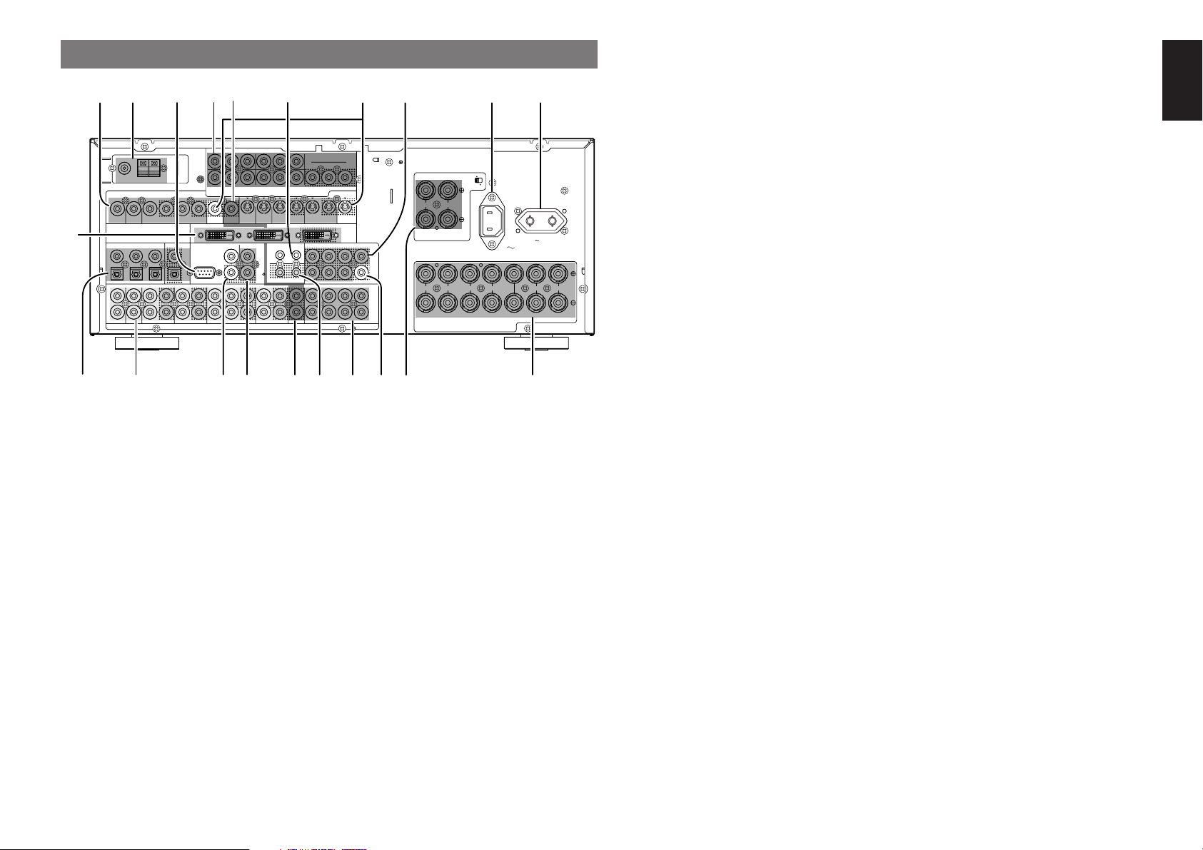
y
RS-232C
The RS-232C port is to be used in conjunction with
an external controller to control the operation of
the SR7500 by using an external device.
The RS-232C port may also be used in the future
to update the operating software of the SR7500 so
that it will be able to support new digital audio
formats and the like as they are introduced.
u
Preamp Outputs
(L, R, SL, SR, SBL, SBR, C)
Jacks for L(front left), R (front right), C (Center), SL
(surround left), SR (surround right), SBL (surround
back left) and SBR (surround back right).
Use these jacks for connection to external power
amplifiers.
i
AC INLET
Plug the supplied power cord into this AC INLET
and then into the power outlet on the wall.
SR7500 can be powered by 230V AC only.
o
AC OUTLETS
Connect the AC power cable of component such
as a DVD or CD player to this outlet.
The marked SWITCHED provides power only
when the SR7500 is turned on and is useful for
components which you use every time you play
your system.
Caution:
•
In order to avoid potential turn-off thumps, anything
plugged into these outlets should be powered up
before the SR7500 is turned on.
•
The capacity of this AC outlet is 100W. Do not
connect devices that consume electricity more than
the capacity of these AC outlet. If the total power
consumption of the connected devices exceeds the
capacity, the protection circuit shuts down the
power supply.
!0
Speaker outputs terminals
Seven terminals are provided for the front (A) left,
front (A) right, front (B) left, front (B) right, front
center, surround left and surround right speakers.
!1
Speaker outputs terminals (SURROUND
BACK / MULTI SPEAKER / SPEAKER C)
Two terminals are provided for the front left, and
right speakers for multi room (2
nd
zone) or
surround back.
The terminals can be used to connect a third set of
speakers by setting the SPEAKER C selector
switch to ON. For connection and use, see page
17.
!2
Subwoofer Output
Connect this jack to the line level input of a powered
subwoofer. If an external subwoofer amplifier is
used, connect this jack to the subwoofer amplifier
input. If you are using two subwoofers, either
powered or with a 2 channel subwoofer amplifier,
connect a “Y” connector to the subwoofer output
jack and run one cable from it to each subwoofer
amplifier.
!3
7.1 CHANNEL or AUX2 INPUT
By connecting a DVD Audio player, SACD
multichannel player, or other components that has
a multichannel port, you can playback the audio
with 5.1 channel or 7.1 channel outputs.
!4
DC TRIGGER output terminal
Connect a device that needs to be triggered by DC
under certain conditions (screen, power strip,
etc…)
Use the system OSD setup menu to determine the
conditions by which these jack will be active.
Note:
• This output voltage is for (status) control only, It
is not sufficient for drive capability.
!5
Multiroom Outputs (Audio L&R, Video)
These are the audio and video output jacks for the
Multi zone (Multi room).
Connect these jacks to optional audio power
amplifiers or video display devices to listen and
view the source selected by the multiroom system
in a remote room.
!6
MULTI ROOM REMOTE IN/OUT terminals
IN: Connect to a multi-room remote control
device, available from your Marantz dealer.
OUT: Connect to the Marantz component
equipped with remote control (RC-5)
terminals in Multi zone (Multi room).
!7
REMOTE CONT. IN/OUT terminals
Connect to a Marantz component equipped with
remote control (RC-5) terminals.
REAR PANEL
e
COMPONENT VIDEO INPUT/OUTPUT
If your DVD player or other device has component
video connectors, be sure to connect them to these
component video connectors on the SR7500. The
SR7500 has 4 component video input connectors
to obtain the color information (Y, C
B
, C
R
) directly
from the recorded DVD signal or other video
component and one component video output
connector to output it directly into the matrix
decoder of the display device.
By sending the pure DVD component video signal
directly, the DVD signal forgoes the extra
processing that normally would degrade the
image. The result is vastly increased image
quality, with incredibly life like colors and crisp
detail.
r
FLASHER IN (Flasher input terminal)
These terminals are to control the unit from each
zone. Connect the control signal from a Keypad,
etc.
t
MONITOR OUT
These are monitor outputs and each one includes
both composite video and S-video configurations.
When connecting two video monitors or televisions,
be aware that the OSD interface can be used with
both MONITOR OUT connections.
q
VIDEO IN/OUT (TV, DVD, VCR1, DSS/VCR2)
These are the video inputs and outputs. There are
4 video inputs and 2 video outputs and each one
includes both composite video and S-video
configurations. Connect VCRs, DVD players, and
other video components to the video inputs.
The 2 video output channels can be used to be
connected to video tape recorders for making
recordings.
w
FM antenna terminal (75 ohms)
Connect an external FM antenna with a coaxial
cable, or a cable network FM source.
AM antenna and ground terminals
Connect the supplied AM loop antenna. Use the
terminals marked “AM” and “GND”. The supplied
AM loop antenna will provide good AM reception in
most areas. Position the loop antenna until you
hear the best reception.
MULTI
OUT
TV DVD
C
IN OUT
S-VIDEO
DVD
DSS/VCR2
C
RS-232C
MULTI RC
IN OUT
DSS/VCR2
IN OUT OUT
VCR1
VCR1
L
SBR
SBL
OUT
PRE
SLL
SRR
DSS/VCR2DVDTV
R
IN
RSW
RC-5
IN
SR
AUDIO
7.1CH
IN
OUT IN
LSL
SBR
SBLCD
IN OUT
SW
OUT
CDR/MDTAPE
OUTIN
IN OUT
VIDEO
MONITOR
OUT
MULTI
VCR1
TV
OUT
(AUX2)
MONITOR
DIGITAL IN DIGITAL OUT
4
1
OPT.
2
5
3
6
COAX.
RL RR
FRONT A
LL
FM
(
75‰
)
ANTENNA
GND AM
COMPONENT
VIDEO
C
B
/
P
B
C
R
/
P
R
C
R
/
P
R
C
R
/
P
R
C
B
/
P
B
C
B
/
P
B
TV
YY
MONITOR OUT
VCR1
DVD DSS/VCR2
Y
SURROUND
100W MAX.
AC OUTLET
SWITCHED
230V 50/60H
Z
OUT
SPEAKER SYSTEMS
FRONT A OR B, CENTER, SURR, SURR BACK
: 6
-
8 OHMS
FRONT A
+
B : 8 OHMS
FLASHER IN
DC OUT
12
12
RL
FRONT B CENTER
SURROUND BACK/
MULTI SPEAKER/
SPEAKER C
ON
OFF
SPEAKER C
OUTPUTINPUT-2INPUT-1
DVI-D
AC IN
tqw e i o
!9 !8
yur
!0
!1!2!4
!7
!6
@0
!5
!5
!3

8
ENGLISH
REMOTE CONTROLLER
RC8500SR
NAMES AND FUNCTIONS
z
Infrared Transmitter and Learning
Sensor
This transmitter emits infrared light. Press the
buttons while pointing the transmitter towards the
infrared receiver window of the SR7500 or other
AV equipment. Be sure to also point towards other
remote controls when using the learning function.
x
POWER ON and OFF buttons
(When AMP mode is selected)
These buttons are used to turn the SR7500 on or
off.
c
SOURCE ON/OFF button
This button is used to turn a specific source (such
as a DVD player) on or off independently from the
rest of the system.
v
M (Mode) button
This button is used to program Macros. Pressing
this button switches between Normal mode and
Macro mode.
The > button is used to move to the next page. Up
to 20 programs (4 pages) can be made. Holding
down the M button for three seconds or more
switches to the Setup mode, where the Setup
menu is shown on the LCD. The Setup menu has
four pages, and the > button is used to move to the
next page. Pressing the > button from page 4
returns you to page 1.
b
D1 to D5 (Direct) buttons
Five types of direct operations can be performed
for each of the 12 source buttons such as the DVD,
television, amplifier, and other AV equipment. The
pages can be switched, so 4 pages × 5 types = 20
operations can be performed for a single source.
The text display can also be changed.
n
> (Page) button
This button is used to switch pages for the Direct
button. The current page is shown on the LCD.
m
VOL (Volume) button
This button is used to adjust the volume for the
amplifier and television.
Note:
• Set the AMP mode to use this button with the
SR7500.
2 31
5 64
8
0
97
MEMO
CLEAR
DSS
AMP
AUX2
AUX1
TAPE
TUNER
CD
CD-R
MD
VCRDVD
TV
SOURCE
OFF
ON/OFF
POWER
ON
D4
D5
D2
M
D1
D3
D5
OK
VOL
CH
PREV
MUTE
MENU
EXIT
GUIDE
TEST
CH.SEL
LIP·SYNC
THX
SURR
7.1CH
ATT
SPK-AB
DISP
OSD
SLEEP
12
LIGHT
Learning Remote Controller
RC8500SR
z
c
v
b
n
x
m
,
.
⁄1
⁄2⁄6
⁄7
⁄8
⁄9
¤0
¤1
⁄3
⁄4
⁄5
⁄0
!8
AUDIO IN/OUT (CD, TAPE, CD-R, TV,
DVD, VCR1, DSS/VCR2)
These are the analog audio inputs and outputs.
There are 7 audio inputs (4 of which are linked to
video inputs) and 4 audio outputs (2 of which are
linked to video outputs). The audio jacks are
nominally labeled for cassette tape decks,
compact disc players, DVD players and etc.... The
audio inputs and outputs require RCA-type
connectors.
!9
DIGITAL INPUT (Dig.1 - 6) / OUTPUT
(coaxial, optical)
These are the digital audio inputs and outputs.
There are 3 digital inputs with coaxial jacks, 3 with
optical jacks.
The inputs accept digital audio signals from a
compact disc, LD, DVD, or other digital source
component.
For digital output, there is 1 coaxial output and 1
optical output.
The digital outputs can be connected to MD
recorders, CD recorders, DAT decks, or other
similar components.
@0
DVI-D INPUT / OUTPUT (SR8500 only)
This unit has two DVI-D inputs and one DVI-D
output. The input function can be selected from the
SETUP MAIN MENU.
,
MUTE button
This button is used to mute the audio for the
SR7500 and television.
Note:
• Set the AMP mode to use this button with the
SR7500.
.
GUIDE button
This button is used to display the menus for the
DVD player, DSS (satellite broadcasting tuner), or
other AV equipment.
(when AMP mode is selected)
This button is used to select the LIP.SYNC mode.
⁄0
EXIT button
(when AMP mode is selected)
This button is used to cancel settings in the setup
menu.
⁄1
Numeric buttons
These buttons are used to switch between 0 to 9 of
the source components. If the source is set to the
amplifier, these buttons are used to perform
operations.
(when AMP mode is selected)
(1) TEST button
Used to enter the test tone menu.
(2) CH SEL. (channel select) button
Used to call up SETUP MAIN MENU and adjust
speaker levels or 7.1 ch input level.
(3) SURR (surround) button
Used to select the surround mode.
(4) 7.1CH button
Press this button to select the output of an external
multi channel decoder.
(5) ATT button
When the input signal is too high and the voice
distorts even by throttling the SR7500 VOLUME
control, turn on this function. “ATT” is indicated
when this function is activated.
The input level is reduced. Attenuator is invalid for
use with the output signal of “REC OUT”.
Note:
• This function is unavailable during the digital
input is selected.
(6) SPK-AB button
Speaker mode is switched in the following
sequence.
A → B → A+B → off
9
ENGLISH
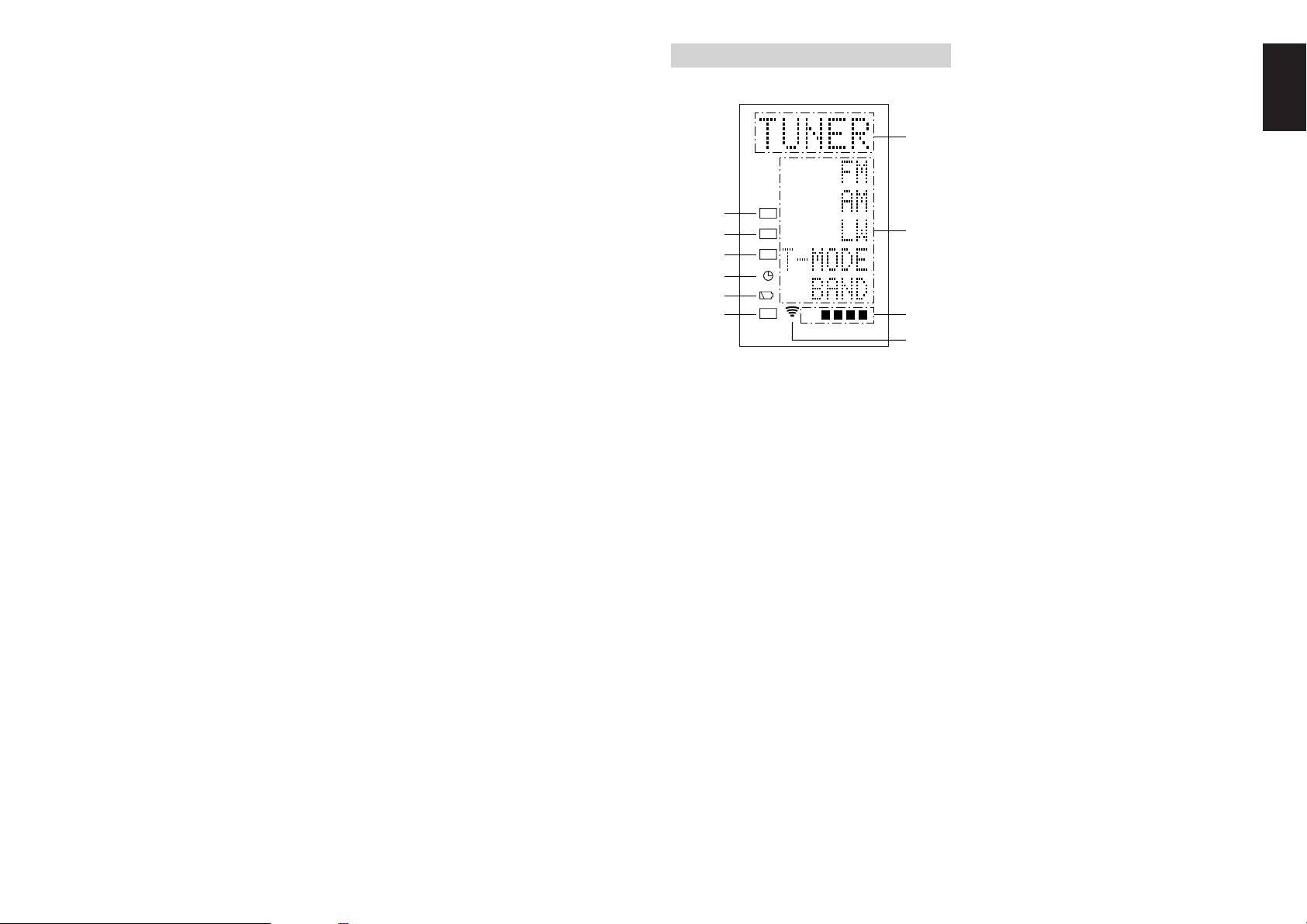
LCD INDICATORS
Information about currently selected source and
direct code names are displayed on the LCD.
A
Source Name indicator
This displays the name of the selected source,
such as DVD, television, or other AV equipment
(up to five characters).
B
Direct Button Name indicator
This displays up to 20 types of button names for
each source. (up to six characters)
C
Page indicator
This displays the current page position.
D
Transmission indicator
This lights up when the remote control is sending a
signal.
E
USE indicator
This is displayed under normal operation.
F
Battery Level indicator
This is displayed when the battery level is low.
G
TIMER indicator
This is displayed when the macro timer is set.
H
MACRO indicator
This is displayed when the remote control is in
macro programming mode.
LEARN
NAME
MACRO
USE
PAGE
123
4
A
B
C
D
E
F
G
H
I
J
(7) DISP. button
Selects the display mode for the front display of the
SR7500.
(8) OSD button
When this button is pressed, the current setting are
displayed on the TV monitor.
(9) SLEEP (sleep timer) button
This button is used for setting the sleep timer. It
can be operated the same way as the button in
unit.
(0) THX button
Use this button to select the THX mode.
⁄2
MEMO button
This button is used to store settings to memory or
program a source.
⁄3
CONTROL button
Thses buttons are used when operating the PLAY,
STOP, PAUSE, and other commands of a source.
Note:
• This button is unavailable for the SR7500.
⁄4
SOURCE button
Thses buttons are used to switch the source of
your A/V Receiver / amplifer. Each time a source
button is pressed, the remote control changes to
the source which was pressed.
This remote control can control 12 types of
equipment. To change the A/V Receiver / amplifier
source, press this button twice within two seconds.
The signal is sent when it is pressed the second
time.
Note:
• Select the AMP as the source to use this remote
controll with the SR7500.
⁄5
LIGHT 1 and 2 buttons
Pressing these buttons will light up the LCD and its
buttons. This lighting time can be set. If the lighting
time is set to 0 seconds, the backlight turns on only
while this button is pressed. The operations for
LIGHT 1 and 2 are identical.
⁄6
CLEAR button
This button is used to erase the memory or
program of a source.
⁄7
MENU button
(when AMP mode is selected)
This button is used to call up the SETUP MAIN
MENU of the SR7500.
⁄8
PREV (Previous) button
This button is used to return to the previous
channel on the television or other device.
Note:
• This button is unavailable for SR7500.
⁄9
CH (Channel) button
This is used to change channels.
¤0
CURSOR buttons
These buttons are used when controlling the
cursor of the SR7500, DVD, or other AV
equipment.
¤1
LCD
Information about the sources and modes are
shown on the LCD.
I
NAME indicator
This is displayed when the remote control is in
renaming mode.
J
LEARN indicator
This is displayed when the remote control is in
learning mode.
10
ENGLISH
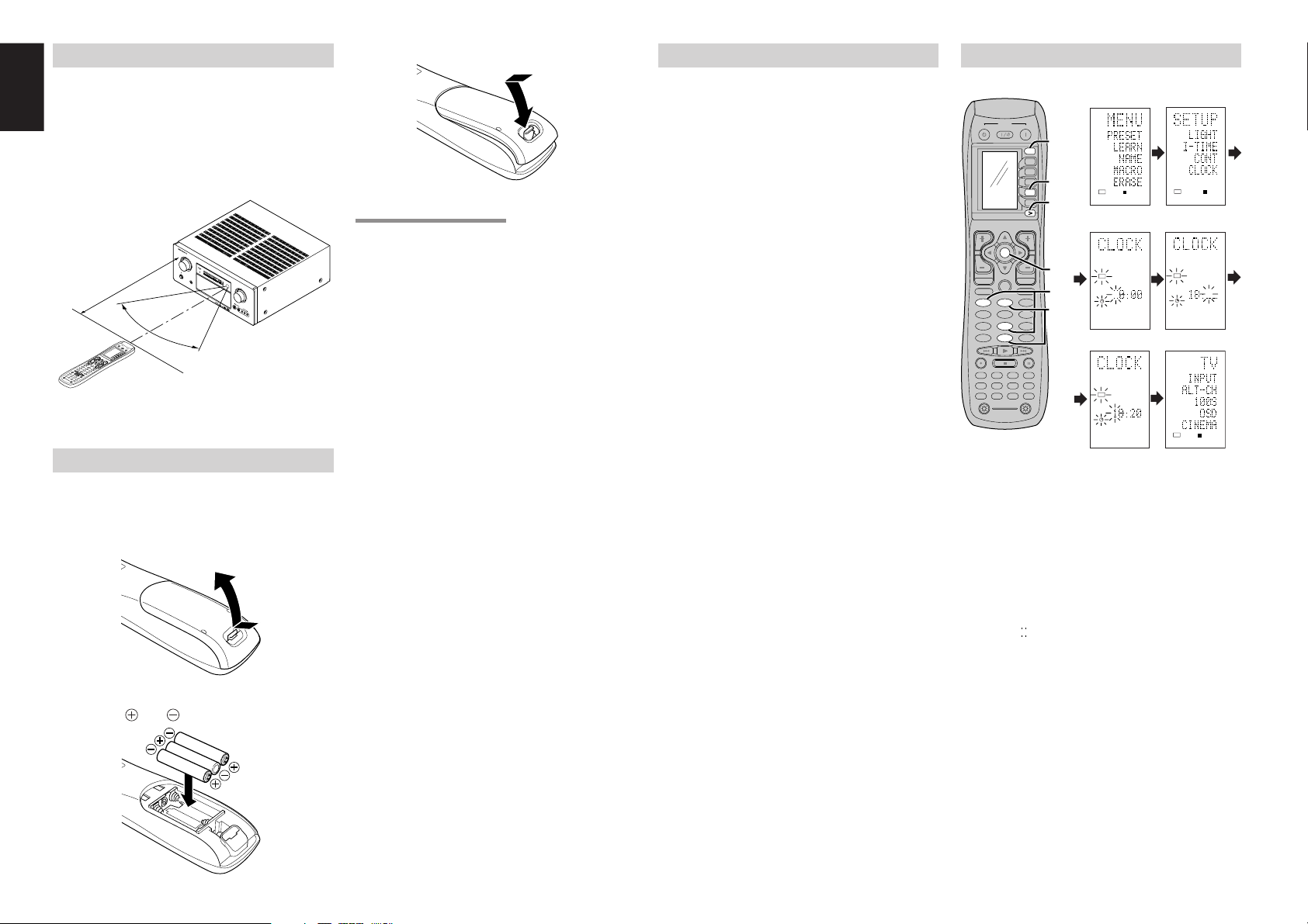
REMOTE CONTROL RANGE
The distance between the transmitter of the
remote control and the IR SENSOR of the SR7500
should be less than 5 meters. If the remote control
is pointed in a direction other than the IR SENSOR
or if there is an obstacle between them, use of the
remote control may not be possible.
Remote-controllable range
LOADING BATTERIES
The life of the batteries used with the remote control
is about 4 months with normal use. Also be sure to
replace batteries earlier when you notice that they
are getting weak.
1.
Remove the back cover.
2.
Insert the new batteries (AAA type) with
correct and polarity.
3.
Close the cover until it clicks.
CAUTIONS ON BATTERIES
• Use “AAA” type batteries in this remote control
unit.
• If the remote control unit does not operate from
close to the main unit, replace the batteries with
new ones, even if less then a year has passed.
• The included battery is only for verifying
operation. Replace it with a new battery as soon
as possible.
• When inserting the batteries, be careful to do so
in the proper direction, following the + and -
marks in the remote control unit’s battery
compartment.
• To prevent damage or battery fluid leakage:
- Do not use a new battery with an old one.
- Do not use two different types of batteries.
- Do not short-circuit, disassemble, heat or
dispose of batteries in flames.
• Remove the batteries when not planning to use
the remote control unit for a long period of time.
• If the batteries should leak, carefully wipe off the
fluid from the inside of the battery compartment,
then insert new batteries.
• When disposing of used batteries, please
comply with governmental regulations or
environmental public instruction’s rules that
apply in your country or area.
Remote control unit (RC8500SR)
SR7500
BATTERY REPLACEMENT INTERVAL
Under normal usage, alkaline batteries last
approximately four months. When the batteries
wear out, a battery mark is displayed on the LCD.
Although the remote control can still be used when
the battery mark is displayed, the batteries should
be replaced as soon as possible. The LCD
eventually starts to flash when buttons are
pressed, the remote control will be unable to
transmit signals or learn codes.
• This remote control uses non-volatile memory
so that the learned codes and macro programs
are retained even if the batteries are removed.
Reset the clock after replacing the batteries.
Safety Precautions for Batteries
Be sure to always observe the following
precautions to prevent fluid leakage, overheating,
fire, breakage, accidental ingestion, and other
accidents.
• If the batteries are left unused for a long period
of time, the battery fluid may leak or the batteries
may corrode.
• Do not use the batteries in the remote control
with the plus and minus polarity reversed.
•
Do not attempt to recharge, heat, or disassemble
the batteries. Do not put the batteries in a fire.
• Do not use the remote control with old batteries
or worn-out batteries inserted.
• Do not use different types of batteries or mix old
and new batteries in the remote control.
• If the remote control is not operating properly,
replace the batteries with new ones.
• If any of the batteries are leaking, completely
wipe up all leaked battery fluid, and then replace
the batteries with new ones.
SETTING THE TIME
Example: Setting to 6:20PM (18:20)
When you bought this remote control and insert
the batteries to the remote control at first, the steps
1 to 3 are skipped.
Starts from step 4 to set the time.
1.
Hold down the M button for three seconds or
more.
The menu is displayed.
2.
Press the > button once.
This displays second page (SETUP).
3.
Press the D4 (CLOCK) direct button.
The “ ” indicator blinks and the clock indicator
displays “0:00”.
4.
Press the 1 and 8 numeric button to set the
hour indicator.
The hour indicator displays “18”.
The minute indicator blinks “_”.
5.
Press the 2 and 0 numeric button to set the
minute indicator.
The minute indicator displays “20”.
The hour indicator blinks.
6.
Press the OK cursor button to start the clock.
The clock starts from 0 second at the time that was
set and return to normal (USE) mode.
Whenever the batteries are replaced, the clock
shows 00:00. Please reset the clock. (The time
setting is not backed up.)
2 31
5 64
8
0
97
MEMO
CLEAR
DSS
AMP
AUX2
AUX1
TAPE
TUNER
CD
CD-R
MD
VCRDVD
TV
SOURCE
OFF
ON/OFF
POWER
ON
D4
D5
D2
M
D1
D3
D5
OK
VOL
CH
PREV
MUTE
MENU
EXIT
GUIDE
TEST
CH.SEL
LIP.SYNC
SURR
7.1CH
ATT
SPK-AB
DISP
OSD
THX
SLEEP
12
LIGHT
Learning Remote Controller
RC8500SR
2.
6.
4.
5.
3.
3.
21
8
0
OK
D4
M
AV
S
U
R
RO
U
ND
R
E
C
E
I
V
E
R
S
R
7
500
P
H
O
NE
S
S
TAN
DB
Y
L
C
R
S
L
S
S
R
L
F
E
DIGITAL
SURR
O
U
ND
DIS
P
MU
LT
I
A
U
TO
T
UNED
ST
SP
K
R
A B
V-OF
F
N
IGHT
PEAK
ANA
LO
G
DIG
IT
A
L
ATT
SLEEP
SU
RR
DIR
ECT
A
U
T
O
DISC 6
.1
MT
X 6.1
PCM
A
A
C
A
UX
1
IN
P
U
T
AUDI
O
S
-
V
I
DE
O
D
I
GI
TAL
V
ID
E
O
L
R
E
N
T
ER
D
O
W
N
U
P
V
O
L
U
M
E
PO
WE
R ON
/OF
F
I
N
P
U
T
S
E
L
E
C
T
O
R
2
3
1
5
6
4
8
0
9
7
M
E
M
O
CL
E
AR
D
S
S
A
M
P
A
U
X
2
A
UX1
T
A
P
E
T
U
N
E
R
C
D
C
D
-
R
M
D
VCR
DVD
T
V
S
O
U
R
C
E
O
F
F
O
N
/
O
F
F
P
O
W
E
R
O
N
D
4
D
5
D
2
M
D
1
D
3
D
5
O
K
VOL
C
H
PR
E
V
MUTE
MENU
E
X
I
T
GU
IDE
T
E
ST
CH.SEL
S
U
R
R
7
.1
C
H
A
T
T
S
P
K
-
A
B
D
I
S
P
O
S
D
SLEEP
1
2
LI
G
HT
Le
a
rning
Re
mote
C
on
troller
R
C
14
00
60°
Approx. 5 m
USE
PAGE
1
USE
PAGE
12
LEARN
LEARN
LEARN
56
34
12
USE
PAGE
12
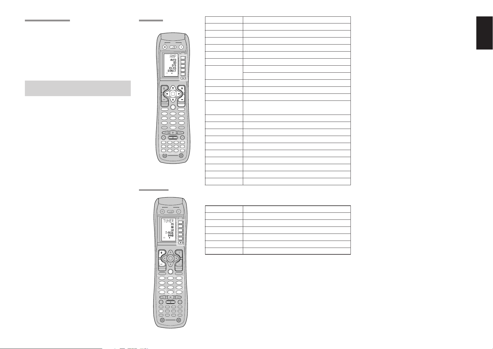
11
ENGLISH
TUNER MODE
AMP MODE
2 31
5 64
8
0
97
MEMO
CLEAR
DSS
AMP
AUX2
AUX1
TAPE
TUNER
CD
CD-R
MD
VCRDVD
TV
SOURCE
OFF
ON/OFF
POWER
ON
D4
D5
D2
M
D1
D3
D5
OK
VOL
CH
PREV
MUTE
MENU
EXIT
GUIDE
TEST
CH.SEL
SURR
7.1CH
ATT
SPK-AB
DISP
OSD
SLEEP
12
LIGHT
Learning Remote Controller
RC8500SR
D1
D5
D4
D2
D3
D5
2 31
5 64
8 97
TEST
CH.SEL
SURR
7.1CH
ATT
LIP.SYNC
SPK-AB
DISP
OSD
THX
SLEEP
TUNER
0
CH
GUIDE
MEMO
CLEAR
USE
PAGE
1
2 31
5 64
8
0
97
MEMO
CLEAR
DSS
AMP
AUX2
AUX1
TAPE
TUNER
CD
CD-R
MD
VCRDVD
TV
SOURCE
OFF
ON/OFF
POWER
ON
D4
D5
D2
M
D1
D3
D5
OK
VOL
CH
PREV
MUTE
MENU
EXIT
GUIDE
TEST
CH.SEL
SURR
7.1CH
ATT
SPK-AB
DISP
OSD
SLEEP
12
LIGHT
Learning Remote Controller
RC8500SR
D1
D5
D4
D2
D3
D5
SOURCE
OFF
ON/OFF
POWER
ON
OK
2 31
5 64
8 97
TEST
CH.SEL
LIP.SYNC
THX
SURR
7.1CH
ATT
SPK-AB
DISP
OSD
SLEEP
MENU
TAPE
DSS
AUX2
AUX1
TUNER
CD
CD-R
MD
VCRDVD
TV
AMP
VOL
EXIT
MUTE
USE
PAGE
123
4
CHECKING THE TIME
To check the time, hold down the > button for three
seconds or more. The current time is displayed for
five seconds.
Note:
• Although the remote control uses a quartz clock,
the time may become out of sync over the course
of operation. Be sure to correct the clock from
time to time.
GENERAL INFORMATION OF
RC8500SR TO SR7500
To control the SR7500 by your RC8500SR, you
have to select the device AMP or TUNER by
pressing the function selector button. Please refer
below for the details in AMP and TUNER mode.
SOURCE ON/OFF Turns the SR7500 on and off
POWER ON Turns the SR7500 on
POWER OFF Turns the SR7500 off
D1 - D5 / >(Page) (Refer to page vi)
VOL +/- Adjust the over all sound level
MUTE Decreases the sound temporarily
Cursor Move the cursor for setting in “On screen display” mode
OK Enter the “On screen display”
Confirms the setting in “On screen display” mode
MENU Displays the current setting on the monitor
EXIT Exits from SETUP MENU
TEST (1) Enter the test tone menu
CH.SEL (2) Call up SETUP MENU and adjusts speaker levels or 7.1ch
input level
SURR (3) Selects the surround mode
7.1CH (4) Selects the 7.1CH IN
ATT (5) Reduces the input level
SPK-AB (6) Selects the speaker system
DISP (7) Changes the front display mode
OSD (8) Selects the “On screen display” on and off
SLEEP (9) Sets the sleep timer function
THX (0) Selects the THX mode
Function selector Selects a particular source component
GUIDE / LIP.SYNC Selects the LIP.SYNC mode
D1 - D5 / >(Page) (Refer to page vi)
CH +/- Selects a preset station up and down
GUIDE Selects the “Frequency direct input”
0–9 Input the numeric
MEMO Enter the tuner preset memory numbers
CLEAR Clears the inputting
TUNER Selects a frequency band
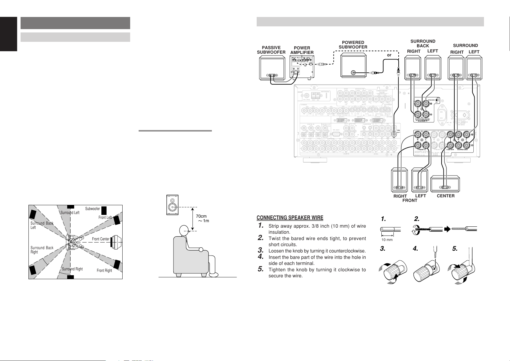
12
ENGLISH
CONNECTIONS
SPEAKER PLACEMENT
The ideal surround speaker system for this unit is
7-speaker systems, using front left and right
speakers, a center speaker, surround left and right
speakers, a surround back left and right speakers,
and a subwoofer.
For best results we recommend that all front
speakers be of the same type, with identical or
similar driver units. This will deliver smooth pans
across the front sound stage as the action moves
from side to side.
Your center channel speaker is very important as
over 80 % of the dialog from a typical motion
picture emanates from the center channel.
It should possess similar sonic characteristics to
the main speakers. Surround channel speakers
need not be identical to the front channel speakers,
but they should be of high quality.
The surround center speaker is useful for playback
of Dolby Digital Surround EX or DTS-ES. One of
the benefits of both Dolby Digital and DTS is that
surround channels are discrete full range, while
they were frequency limited in earlier “Pro Logic”
type systems.
Bass effects are an important part of home theater.
For optimal enjoyment a subwoofer should be used
as it is optimized for low frequency reproduction. If
you have full range front speakers, however, they
may be used in place of a subwoofer with proper
setting of the switches in the menu system.
Front left and right speakers
We recommend to set the front L and R speakers
with 45-60 degrees from the listening position.
Center speaker
Align the front line of the center speaker with the
front L/R speakers. Or place the center speaker a
little backward from the line.
Surround left and right speakers
When the SR7500 is used in surround operation,
the preferred location for surround speakers is on
the side walls of the room, at or slightly behind the
listening position.
The center of the speaker should face into the
room.
Surround back left and right speakers
Surround back speakers are required when a full
7.1-channel system is installed.
Speakers should be placed on a rear wall, behind
the listening position.
The center of the speaker should face into the
room.
Subwoofer
We recommend using a sub-woofer to have maximum
bass effect. Sub-woofer bears only low frequency
range so you can place it any where in the room.
HEIGHT OF THE SPEAKER UNITS
Front left and right speakers, and a center speaker
Align the tweeters and mid-range drivers on the
three front speakers at the same height, as best as
possible.
Surround left and right speakers, and surround
back speaker
Place the surround left, right and surround back
speakers higher than your ears by about 70cm–
1m. Also place the speakers at the same height, sa
best as possible.
Note:
• Use magnetically-shielded speakers for front left,
right and the center speakers when the speakers
are installed near the TV and the TV is a monitor
type.
90
°
110
°
22
°
30
°
135
°
150
°
0
°
CONNECTING SPEAKERS
ACIN
MULTI
OUT
TV DVD
C
IN OUT
S-VIDEO
DVD
DSS/VCR2
C
RS-232C
MULTIRC
IN OUT
DSS/VCR2
IN OUT OUT
VCR1
VCR1
L
SBR
SBL
OUT
PRE
SLL
SRR
DSS/VCR2DVDTV
R
IN
RSW
RC-5
IN
SR
AUDIO
7.1CH
IN
OUT IN
LSL
SBR
SBLCD
IN OUT
SW
OUT
CDR/MDTAPE
OUTIN
IN OUT
VIDEO
MONITOR
OUT
MULTI
VCR1
TV
OUT
(AUX2)
MONITOR
DIGITALIN DIGITALOUT
4
1
OPT.
2
5
3
6
COAX.
RL RR
FRONTA
LL
FM
(
75½
)
ANTENNA
GND AM
COMPONENT
VIDEO
C
B
/
P
B
C
R
/
P
R
C
R
/
P
R
C
R
/
P
R
C
B
/
P
B
C
B
/
P
B
TV
YY
MONITOROUT
VCR1
DVD DSS/VCR2
Y
SURROUND
100WMAX.
ACOUTLET
SWITCHED
230V 50/60H
Z
OUT
SPEAKERSYSTEMS
FRONTA ORB, CENTER,SURR, SURRBACK
:6
-
8 OHMS
FRONTA
+
B :8 OHMS
FLASHERIN
DCOUT
12
12
RL
FRONTB CENTER
SURROUNDBACK/
MULTISPEAKER/
SPEAKERC
ON
OFF
SPEAKERC
OUTPUTINPUT-2INPUT-1
DVI-D
RR
FRONTA
LL
SURROUNDCENTER
RL
SURROUNDBACK/
MULTISPEAKER/
SPEAKERC
ON
OFF
SPEAKERC
OUT
PRE
SW
INVERT
OUTPUT
INPUT
LEVEL
BTL REMOTECONT.EXT.CONT. IN
VIDEO/
+5~13VDC
SYSTEMOUT O UT
INPUT
MASTERSLAVE
MIN MAX
IN
F
U
S
E
SPEAKERSYSTEM
MINIMUM4OHMS
POWERED
SUBWOOFER
POWER
AMPLIFIER
PASSIVE
SUBWOOFER
FRONT
RIGHT
LEFT
SURROUND
SURROUND
BACK
CENTER
or
RIGHT
LEFT
CONNECTING SPEAKER WIRE
1.
Strip away approx. 3/8 inch (10 mm) of wire
insulation.
2.
Twist the bared wire ends tight, to prevent
short circuits.
3.
Loosen the knob by turning it counterclockwise.
4.
Insert the bare part of the wire into the hole in
side of each terminal.
5.
Tighten the knob by turning it clockwise to
secure the wire.
1. 2.
3. 4. 5.
10 mm
Front Right
Front Left
Front Center
Surround Left
Subwoofer
Surround Back
Left
Surround Right
Surround Back
Right
RIGHT
LEFT
70cm
1m
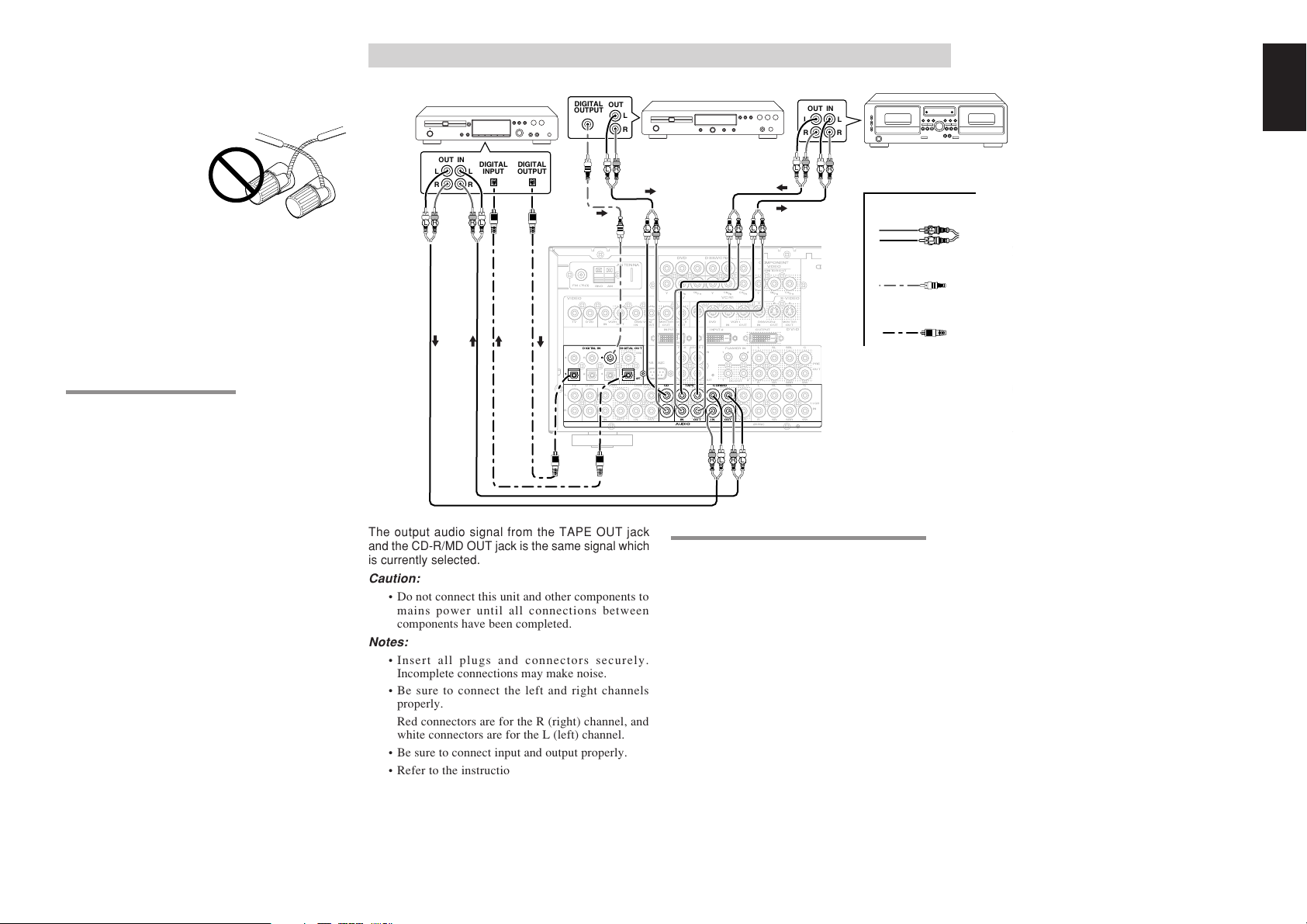
13
ENGLISH
Caution:
•
Be sure to use speakers with the specified impedance
as shown on the rear panel of this unit.
•
To prevent damage to circuitry, do not let the bare
speaker wires touch
each other and do
not let them touch
any metal part of
this unit.
• Do not touch the
speaker terminals
when the power is
on. It may cause
you to receive an electric shocks.
• Do not connect more than one speaker cable to
one speaker terminal. Doing so may damage this
unit.
Note:
•
Be sure to connect the positive and negative cables
for the speaker properly. If they are miss-connected,
the signal phase will be reversed and the signal
quality will be corrupted.
CONNECTING A SUBWOOFER
Use the PRE OUT SUBWOOFER jack to connect
a powered subwoofer (power amplifier built in ).
If your subwoofer is a passive type (power amplifier
is not built in), connect a monaural power amplifier
to the PRE OUT SUBWOOFER jack and connect
the subwoofer to the amplifier.
CONNECTING AUDIO COMPONENTS
ACIN
MULTI
OUT
TV DVD
C
IN OUT
S-VIDEO
DVD
DSS/VCR2
C
RS-232C
MULTIRC
IN OUT
DSS/VCR2
IN OUT OUT
VCR1
VCR1
L
SBR
SBL
OUT
PRE
SLL
SRR
DSS/VCR2DVDTV
R
IN
RSW
RC-5
IN
SR
AUDIO
7.1CH
IN
OUT IN
LSL
SBR
SBLCD
IN OUT
SW
OUT
CDR/MDTAPE
OUTIN
IN OUT
VIDEO
MONITOR
OUT
MULTI
VCR1
TV
OUT
(AUX2)
MONITOR
DIGITALIN DIGITALOUT
4
1
OPT.
2
5
3
6
COAX.
RL RR
FRONTA
LL
FM
(
75½
)
ANTENNA
GND AM
COMPONENT
VIDEO
C
B
/
P
B
C
R
/
P
R
C
R
/
P
R
C
R
/
P
R
C
B
/
P
B
C
B
/
P
B
TV
YY
MONITOROUT
VCR1
DVD DSS/VCR2
Y
SURROUND
100WMAX.
ACOUTLET
SWITCHED
230V 50/60H
Z
OUT
SPEAKERSYSTEMS
FRONTA ORB, CENTER,SURR, SURRBACK
:6
-
8 OHMS
FRONTA
+
B :8 OHMS
FLASHERIN
DCOUT
12
12
RL
FRONTB CENTER
SURROUNDBACK/
MULTISPEAKER/
SPEAKERC
ON
OFF
SPEAKERC
OUTPUTINPUT-2INPUT-1
DVI-D
AUDIO
IN
CD
IN OUT OUT
CDR/MDTAPE
DIGITALIN
11
66
DIGITALOUT
OPT.
OUT IN
L
R
L
R
OUT
L
R
L R
L R
L R
RL RL RL
OUT IN
L
R
L
R
DIGITAL
INPUT
DIGITAL
OUTPUT
DIGITAL
OUTPUT
R L
R L R L
RL
L R
The output audio signal from the TAPE OUT jack
and the CD-R/MD OUT jack is the same signal which
is currently selected.
Caution:
• Do not connect this unit and other components to
mains power until all connections between
components have been completed.
Notes:
• Insert all plugs and connectors securely.
Incomplete connections may make noise.
• Be sure to connect the left and right channels
properly.
Red connectors are for the R (right) channel, and
white connectors are for the L (left) channel.
• Be sure to connect input and output properly.
• Refer to the instructions for each component that
is connected to this unit.
• Do not bind audio/video connection cables with
power cords and speaker cables this will result in
generating a hum or other noise.
CONNECTING DIGITAL AUDIO COMPONENTS
• There are 6 digital inputs, 3 coaxial jacks and 3
optical jacks, on the rear panel. You can use
these jacks to input PCM, Dolby Digital and DTS
bitstream signals from a CD, DVD, or other
digital source components.
• There is one digital output coaxial jack and one
optical output jack on the rear panel. These
jacks can be connected to a CD recorder-, or a
MD deck inputs, respectively.
• Refer to the instructions for each component. To
setup the digital audio format of DVD player, or
other digital source’s connected to digital input
jacks.
• Use fiber optical cables (optical) for DIG-1,2,3
input jacks. Use 75 ohms coaxial cables (for
digital audio or video) for DIG-4, 5, 6 input jacks.
• You can designate the input for each digital
input/output jacks according to your component.
See page 19.
CD RECORDER / MD DECK
CD PLAYER
TAPE DECK
ANALOG AUDIO
DIGITAL AUDIO
(COAXIAL)
DIGITAL AUDIO
(OPTICAL)
Notes:
• There is no Dolby Digital RF input jack. Please
use an external RF demodulator Dolby Digital
decoder when connecting the Dolby Digital RF
output jack of the video disc player to the digital
input jack.
• The digital signal jacks on this unit conform to the
EIA standard. If you use a cable that does not
conform to this standard, this unit may not
function properly.
• Each type of audio jack works independently.
Signals input through the digital and analog jacks
are output through the corresponding digital and
analog jacks, respectively.
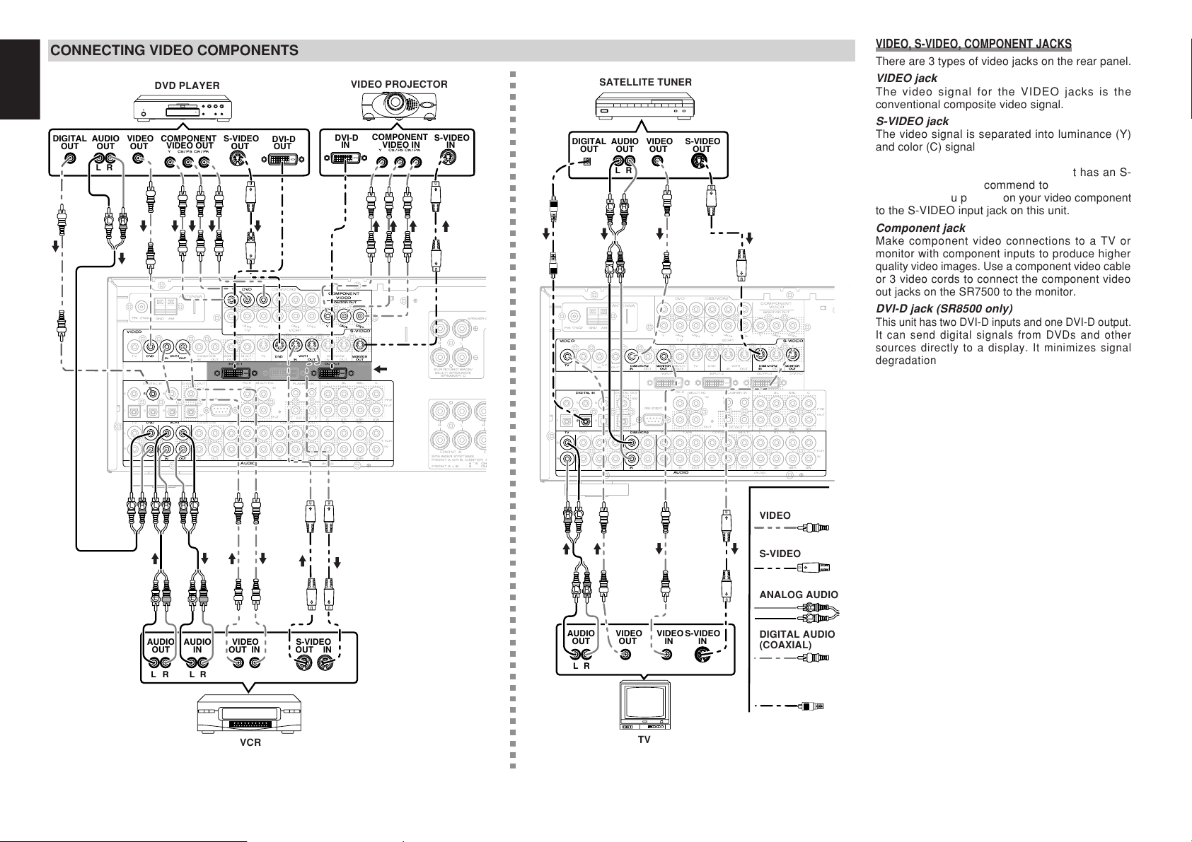
14
ENGLISH
MULTI
OUT
TV DVD
C
IN OUT
S-VIDEO
DVD
DSS/VCR2
C
RS-232C
MULTIRC
IN OUT
DSS/VCR2
IN OUT OUT
VCR1
VCR1
L
SBR
SBL
OUT
PRE
SLL
SRR
DSS/VCR2DVDTV
R
IN
RSW
RC-5
IN
SR
AUDIO
7.1CH
IN
OUT IN
LSL
SBR
SBLCD
IN OUT
SW
OUT
CDR/MDTAPE
OUTIN
IN OUT
VIDEO
MONITOR
OUT
MULTI
VCR1
TV
OUT
(AUX2)
MONITOR
DIGITALIN DIGITALOUT
4
1
OPT.
2
5
3
6
COAX.
RR
FRONTA
L
FM
(
75½
)
ANTENNA
GND AM
COMPONENT
VIDEO
C
B
/
P
B
C
R
/
P
R
C
R
/
P
R
C
R
/
P
R
C
B
/
P
B
C
B
/
P
B
TV
YY
MONITOROUT
VCR1
DVD DSS/VCR2
Y
OUT
SPEAKERSYSTEMS
FRONTA ORB, CENTER,S
:6
-
8OH
FRONTA
+
B:8 OH
FLASHERIN
DCOUT
12
12
RL
F
SURROUNDBACK/
MULTISPEAKER/
SPEAKERC
SPEAKERC
OUTPUTINPUT-2INPUT-1
DVI-D
DVD
IN OUT
VCR1
VIDEO
DVD
IN OUT
VCR1
S-VIDEO
OUT
MONITOR
COMPONENT
VIDEO
C
R
/
P
R
C
B
/
P
B
Y
MONITOROUT
5
VCR1DVD
AUDIO
IN OUT
DVD
OUTPUTINPUT-1
LR
AUDIO
OUT
DIGITAL
OUT
VIDEO
OUT
S-VIDEO
OUT
S-VIDEO
IN
DVI-D
IN
LR
AUDIO
OUT
AUDIO
IN
LR
VIDEO
OUT IN
S-VIDEO
OUT IN
YC
B
/P
B
C
R
/P
R
COMPONENT
VIDEO OUT
YC
B
/P
B
C
R
/P
R
COMPONENT
VIDEO IN
DVI-D
OUT
L R L R
L R
L R L R LR
MULTI
OUT
TV DVD
C
IN OUT
S-VIDEO
DVD
DSS/VCR2
C
RS-232C
MULTIRC
IN OUT
DSS/VCR2
IN OUT OUT
VCR1
VCR1
L
SBR
SBL
OUT
PRE
SLL
SRR
DSS/VCR2DVDTV
R
IN
RSW
RC-5
IN
SR
AUDIO
7.1CH
IN
OUT IN
LSL
SBR
SBLCD
IN OUT
SW
OUT
CDR/MDTAPE
OUTIN
IN OUT
VIDEO
MONITOR
OUT
MULTI
VCR1
TV
OUT
(AUX2)
MONITOR
DIGITALIN DIGITALOUT
4
1
OPT.
2
5
3
6
COAX.
FM
(
75½
)
ANTENNA
GND AM
COMPONENT
VIDEO
C
B
/
P
B
C
R
/
P
R
C
R
/
P
R
C
R
/
P
R
C
B
/
P
B
C
B
/
P
B
TV
YY
MONITOROUT
VCR1
DVD DSS/VCR2
Y
OUT
FLASHERIN
DCOUT
12
12
OUTPUTINPUT-2INPUT-1
DVI-D
TV
VIDEO
DSS/VCR2
IN OUT
MONITOR
IN
S-VIDEO
OUT
MONITOR
LL
DSS/VCR2
RR
AUDIO
IN
DIGITALIN
2
TV
DSS/VCR2
LR
AUDIO
OUT
DIGITAL
OUT
VIDEO
OUT
S-VIDEO
OUT
AUDIO
OUT
LR
VIDEO
OUT
S-VIDEO
IN
VIDEO
IN
LR
L R
L R
L R
L R
CONNECTING VIDEO COMPONENTS
ANALOG AUDIO
VIDEO
S-VIDEO
DVD PLAYER
VIDEO PROJECTOR
SATELLITE TUNER
DIGITAL AUDIO
(COAXIAL)
VCR
TV
VIDEO, S-VIDEO, COMPONENT JACKS
There are 3 types of video jacks on the rear panel.
VIDEO jack
The video signal for the VIDEO jacks is the
conventional composite video signal.
S-VIDEO jack
The video signal is separated into luminance (Y)
and color (C) signals for the S-VIDEO jack. The S-
VIDEO signals enables high-quality color
reproduction. If your video component has an S-
VIDEO output, we recommend to use it. Connect
the S-VIDEO output jack on your video component
to the S-VIDEO input jack on this unit.
Component jack
Make component video connections to a TV or
monitor with component inputs to produce higher
quality video images. Use a component video cable
or 3 video cords to connect the component video
out jacks on the SR7500 to the monitor.
DVI-D jack (SR8500 only)
This unit has two DVI-D inputs and one DVI-D output.
It can send digital signals from DVDs and other
sources directly to a display. It minimizes signal
degradation caused by analog conversion so that
high quality images can be enjoyed. Select an input
source from the SETUP MAIN MENU. (See page 19.)
Notes:
•
Be sure to connect the left and right audio channels
properly.
Red connectors are for the R (right) channel, and
white connectors are the for L (left) channel.
• Be sure to connect the inputs and outputs of the
video signals properly.
•
If you connect the S-VIDEO or component signal to
the S-VIDEO or component jack on this unit, it is not
necessary to connect the conventional video signal to
the VIDEO (composite) jack. If you use both video
inputs, this unit gives priority to the S-VIDEO signal.
• Each type of video jack works independently.
Signals input to the VIDEO (composite) and S-
VIDEO jacks or component are output to the
corresponding VIDEO (composite) and S-VIDEO
or component jacks, respectively.
•
This unit has the “TV-AUTO ON/OFF” function to
turn the TV ON or OFF automatically, by sensing
the incoming video signal from the VIDEO jacks.
• You may need to setup the digital audio output
format of your DVD player, or other digital source
components. Refer to the instructions of the each
component connected to the digital input jacks.
• There is no Dolby Digital RF input jack. Please
use an external RF demodulator with a Dolby
Digital decoder to connect a video disc player
which has a Dolby Digital RF output jack to the
digital input jack on this unit.
DIGITAL AUDIO
(OPTICAL)
SR8500
only
Note (SR8500 only):
• When a device with DVI
output that supports
HDCP is connected to a
device that does not
support HDCP, signals
are not output. To view
images in DVI, it is
necessary to connect a
display that supports
HDCP.
• There may be no Image
output if connected to a
TV or display that is not
compatible with the above
format.
• Refer to the instruction
manual of the TV or
display to be connected to
this unit for detailed
information regarding the
DVI-D terminal.
*HDCP: High-bandwidth Digital
Content Protection
 Loading...