


 Loading...
Contents |
Connections |
Playback |
Settings |
Tips |
Appendix |
|
|
|
|
|
|
AV Surround Receiver
SR5009
You can print more than one page of a PDF onto a single sheet of paper. |
Owner’s Manual |
|
Front panel |
Display |
Rear panel |
1 |
Remote |
Index |

Contents |
Connections |
Playback |
Settings |
Tips |
Appendix |
Accessories |
7 |
|
|
|
Inserting the batteries |
8 |
|
|
Operating range of the remote control unit |
8 |
|
|
Features |
9 |
|
|
High quality sound |
9 |
|
|
High performance |
9 |
|
|
Easy operation |
12 |
|
Part names and functions |
13 |
|
|
|
Front panel |
13 |
|
|
Display |
16 |
|
|
Rear panel |
18 |
|
|
Remote control unit |
21 |
|
Connections |
|
|
|
Connecting speakers |
25 |
|
|
|
Speaker installation |
25 |
|
|
Speaker connection |
28 |
|
|
Speaker configuration and Amp Assign settings |
31 |
|
|
Connecting a TV |
39 |
|
|
Connection 1 : TV equipped with an HDMI connector and |
40 |
|
|
compatible with the ARC (Audio Return Channel) |
|
|
|
Connection 2 : TV equipped with an HDMI connector and |
41 |
|
|
incompatible with the ARC (Audio Return Channel) |
|
|
|
Connection 3 : TV equipped without an HDMI connector |
42 |
|
Connecting a playback device |
43 |
|
|
|
Connecting a DVD player or Blu-ray Disc player |
44 |
|
|
Connecting a set-top box (Satellite tuner/cable TV) |
45 |
|
|
Connecting a video camcorder or game console |
46 |
|
|
Connecting a device with a multi-channel output connector |
47 |
|
|
Connecting an iPod or USB memory device to the USB port |
48 |
|
Connecting an FM/AM antenna |
50 |
||
Connecting to a home network (LAN) |
52 |
|
|
|
Wired LAN |
52 |
|
|
Wireless LAN |
53 |
|
|
Connecting an external control device |
54 |
|
|
REMOTE CONTROL jacks |
54 |
|
|
DC OUT jack |
55 |
|
|
Connecting the power cord |
56 |
|
Playback |
|
|
|
Basic operation |
58 |
||
|
Turning the power on |
58 |
|
|
Selecting the input source |
58 |
|
|
Adjusting the volume |
59 |
|
|
Turning off the sound temporarily (Muting) |
59 |
|
|
Playback a DVD player/Blu-ray Disc player |
59 |
|
Front panel |
Display |
Rear panel |
2 |
Remote |
Index |
Contents |
Connections |
Playback |
Settings |
Tips |
Appendix |
Playing an iPod |
60 |
|
|
|
Listening to music on an iPod |
61 |
|
|
iPod Browse Mode settings |
62 |
|
|
Performing repeat playback |
64 |
|
|
Performing random playback |
64 |
|
Playing a USB memory device |
65 |
|
|
|
Playing files stored on USB memory devices |
66 |
|
|
Listening to music on a Bluetooth device |
68 |
|
|
Pairing with a Bluetooth device |
69 |
|
|
Playing a Bluetooth device |
70 |
|
|
Pairing with the Pairing Mode |
72 |
|
|
Listening to FM/AM broadcasts |
73 |
|
|
Listening to FM/AM broadcasts |
74 |
|
|
Tuning in by entering the frequency (Direct Tune) |
75 |
|
|
Changing the tune mode (Tune Mode) |
76 |
|
|
Tuning in to stations and presetting them automatically (Auto |
76 |
|
|
Preset Memory) |
|
|
|
Presetting the current broadcast station (Preset Memory) |
77 |
|
|
Listening to preset stations |
77 |
|
|
Specify a name for the preset broadcast station (Preset Name) |
78 |
|
|
Skipping preset broadcast stations (Preset Skip) |
79 |
|
|
Cancelling Preset Skip |
80 |
|
Listening to Internet Radio |
81 |
|
|
|
Listening to Internet Radio |
82 |
|
|
Playing the last played Internet Radio station |
83 |
|
|
Using vTuner to add Internet Radio stations to favorites |
84 |
|
|
|
|
|
Playing back files stored on a PC and NAS |
85 |
|
|
|
Applying media sharing settings |
86 |
|
|
Playing back files stored on a PC and NAS |
87 |
|
Viewing photographs on the Flickr site |
89 |
|
|
|
Viewing photographs shared by particular users |
90 |
|
|
Viewing all photographs on Flickr |
92 |
|
|
Listening to Pandora® |
93 |
|
|
Listening to Pandora® |
94 |
|
|
Creating a new station |
96 |
|
|
Listening to an existing station |
97 |
|
|
Listening to created radio stations at random |
97 |
|
|
Giving feedback and managing stations |
98 |
|
|
Sign Out |
99 |
|
|
Listening to SiriusXM Internet Radio |
100 |
|
|
Listening to SiriusXM Internet Radio |
101 |
|
|
Sign Out |
102 |
|
Front panel |
Display |
Rear panel |
3 |
Remote |
Index |

Contents |
Connections |
Playback |
Settings |
Tips |
Appendix |
AirPlay function |
103 |
|
|
Playing songs from your iPhone, iPod touch or iPad |
104 |
|
Playing iTunes music with this unit |
104 |
|
Selecting multiple speakers (devices) |
105 |
|
Perform iTunes playback operations with the remote control unit |
105 |
|
of this unit |
|
Spotify Connect function |
106 |
|
|
Playing Spotify music with this unit |
106 |
|
Convenience functions |
107 |
|
Performing repeat playback |
108 |
|
Performing random playback |
108 |
|
Registering to Favorites |
109 |
|
Playing back content added to the “Save to Favorites” |
109 |
|
Deleting content added to favorites |
110 |
|
Searching content with keywords (Text Search) |
110 |
|
Playing back music and a favorite picture at the same time |
111 |
|
(Slideshow) |
|
|
Setting the Slideshow Interval |
112 |
|
Adjusting the volume of each channel to match the input source |
113 |
|
(Channel Level Adjust) |
|
|
Adjusting the tone (Tone) |
114 |
|
Displaying your desired video during audio playback (Video |
115 |
|
Select) |
|
|
Adjusting the picture quality for your viewing environment (Picture |
116 |
|
Mode) |
|
|
Playing the same music in all zones (All Zone Stereo) |
117 |
Selecting a sound mode |
118 |
|
|
|
Selecting a sound mode |
119 |
|
|
Direct playback |
120 |
|
|
Pure Direct playback |
120 |
|
|
Auto surround playback |
121 |
|
HDMI control function |
130 |
|
|
|
Setting procedure |
130 |
|
Sleep timer function |
131 |
|
|
|
Using the sleep timer |
132 |
|
Smart select function |
133 |
||
|
Calling up the settings |
134 |
|
|
Changing the settings |
135 |
|
Web control function |
136 |
||
|
Controlling the unit from a web control |
136 |
|
Panel lock function |
138 |
|
|
|
Disabling all key button operations |
138 |
|
|
Disabling all button operations except VOLUME |
138 |
|
|
Canceling the Panel lock function |
139 |
|
Remote lock function |
140 |
||
|
Disabling the sensor function of the remote control unit |
140 |
|
|
Enabling the remote sensor function |
140 |
|
|
Playback in ZONE2 (Separate room) |
141 |
|
|
Connecting ZONE2 |
141 |
|
|
Playback in ZONE2 |
143 |
|
Front panel |
Display |
Rear panel |
4 |
Remote |
Index |

Contents |
Connections |
Playback |
Settings |
Tips |
Appendix |
Settings
Menu map |
145 |
|
|
Menu operations |
148 |
|
Inputting characters |
149 |
|
Using the keyboard screen |
150 |
Audio |
151 |
|
|
Dialog Level Adjust |
151 |
|
Subwoofer Level Adjust |
151 |
|
Surround Parameter |
152 |
|
M-DAX |
156 |
|
Audio Delay |
157 |
|
Volume |
157 |
|
Audyssey |
158 |
|
Graphic EQ |
160 |
Video |
162 |
|
|
Picture Adjust |
162 |
|
HDMI Setup |
164 |
|
Output Settings |
168 |
|
On Screen Display |
172 |
|
TV Format |
173 |
Inputs |
174 |
||
|
Input Assign |
174 |
|
|
Source Rename |
176 |
|
|
Hide Sources |
176 |
|
|
Source Level |
176 |
|
|
Input Select |
177 |
|
|
Speakers |
178 |
|
Audyssey® Setup |
178 |
|
|
|
Procedure for speaker settings (Audyssey® Setup) |
180 |
|
|
Error messages |
186 |
|
|
Retrieving Audyssey® Setup settings |
187 |
|
Manual Setup |
188 |
|
|
|
Amp Assign |
188 |
|
|
Speaker Config. |
189 |
|
|
Distances |
191 |
|
|
Levels |
192 |
|
|
Crossovers |
193 |
|
|
Bass |
194 |
|
|
Front Speaker |
195 |
|
Front panel |
Display |
Rear panel |
5 |
Remote |
Index |

Contents |
Connections |
Playback |
Settings |
Tips |
Appendix |
Network |
196 |
|
|
Information |
196 |
|
Connection |
196 |
|
Wi-Fi Setup |
197 |
|
Settings |
199 |
|
IP Control |
200 |
|
Friendly Name |
201 |
|
Diagnostics |
201 |
|
Maintenance Mode |
202 |
General |
203 |
|
|
Language |
203 |
|
ECO |
203 |
|
ZONE2 Setup |
205 |
|
Zone Rename |
206 |
|
Smart Select Names |
206 |
|
Trigger Out |
207 |
|
Front Display |
207 |
|
Information |
208 |
|
Usage Data |
209 |
|
Firmware |
210 |
|
Setup Lock |
212 |
Limiting the operating zone with the remote control |
213 |
|
Tips
|
Tips |
215 |
|
|
Troubleshooting |
217 |
|
|
Resetting factory settings |
233 |
|
Appendix |
|
|
|
About HDMI |
234 |
|
|
Video conversion function |
237 |
|
|
Playing back a USB memory devices |
239 |
|
|
Playing back a Bluetooth device |
240 |
|
|
Playing back a file saved on a PC or NAS |
241 |
|
|
Playing back Internet Radio |
242 |
|
|
Personal memory plus function |
242 |
||
Last function memory |
242 |
||
Sound modes and channel output |
243 |
|
|
Sound modes and surround parameters |
244 |
|
|
Types of input signals, and corresponding sound modes |
247 |
|
|
Explanation of terms |
250 |
|
|
Trademark information |
260 |
||
Specifications |
262 |
||
Index |
267 |
|
|
License |
270 |
|
|
Front panel |
Display |
Rear panel |
6 |
Remote |
Index |
Contents |
Connections |
Playback |
Settings |
Tips |
Appendix |
Thank you for purchasing this Marantz product.
To ensure proper operation, please read this owner’s manual carefully before using the product.
After reading this manual, be sure to keep it for future reference.
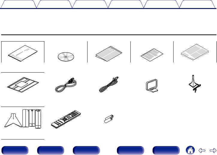
Accessories
Check that the following parts are supplied with the product.
Quick Start Guide |
CD-ROM |
Safety Instructions |
Notes on radio |
Warranty |
|
(Owner’s Manual) |
|
|
(for USA/for CANADA) |
Cable labels |
Power cord |
FM indoor antenna |
AM loop antenna |
Sound calibration |
|
|
|
|
microphone |
|
|
|
|
(ACM1HB) |
Microphone stand |
Remote control unit |
R03/AAA batteries |
|
|
|
(RC024SR) |
|
|
|
Front panel |
Display |
Rear panel |
7 |
Remote |
Index |
Contents |
Connections |
Playback |
Settings |
Tips |
Appendix |
|
|
|
|
|
|
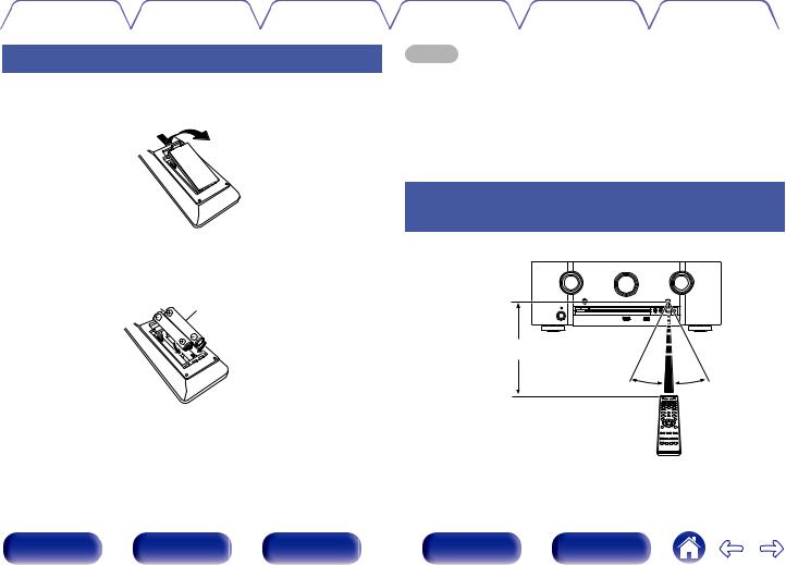
Inserting the batteries
1Remove the rear lid in the direction of the arrow and remove it.
2Insert two batteries correctly into the battery compartment as indicated.
R03/AAA batteries
NOTE
0 To prevent damage or leakage of battery fluid:
0Do not use a new battery together with an old one.
0Do not use two different types of batteries.
0Remove the batteries from the remote control unit if it will not be in use for long periods.
0If the battery fluid should leak, carefully wipe the fluid off the inside of the battery compartment and insert new batteries.
Operating range of the remote control unit
Point the remote control unit at the remote sensor when operating it.
Approx. 23 ft/7 m
30°  30°
30°
3Put the rear cover back on.
Front panel |
Display |
Rear panel |
8 |
Remote |
Index |
Contents |
Connections |
Playback |
Settings |
Tips |
Appendix |
Features
High quality sound
0With discrete circuit technology, the power amplifier provides identical quality for all 7-channels (140 Watts x 7-channels)
For optimum realism and stunning dynamic range, the power amplifier section features discrete power devices (not integrated circuitry).
By using high current, high power discrete power devices, the amplifier is able to easily drive high quality speakers.
High performance
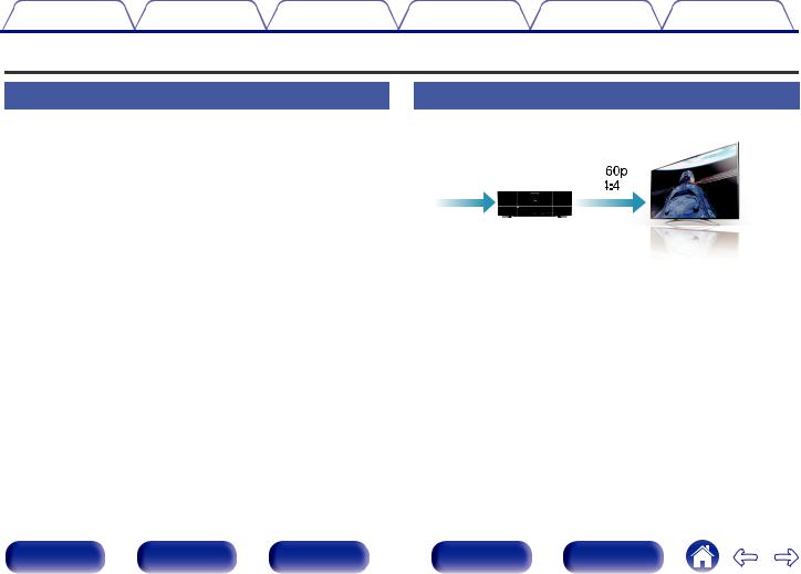
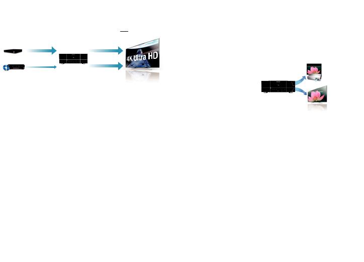
0 4K 60Hz input/output supported
4K 60p |
4K |
4:4:4 |
|
When 4K Ultra HD (High Definition) is used, an input/output speed of 60 frames per second (60p) is achieved for video signals. When connected to 4K Ultra HD and 60p video signal input compatible TV, you can enjoy the sense of realism only available from high-definition images, even when viewing fast-moving video.
This unit also supports image processing for 4K 60p, 4:4:4 and 24-bit videos. By processing the video at the original resolution, this unit lets you enjoy flawless, high-definition picture quality.
Front panel |
Display |
Rear panel |
9 |
Remote |
Index |
Contents |
Connections |
Playback |
Settings |
Tips |
Appendix |
0Digital video processor upscales analog video signals (SD resolution) to HD (720p/1080p) and 4K (v p. 234)
4K |
4K |
Up to 1080p |
4K Up |
scaling |
0HDMI connections enable connection to various digital AV devices (8 inputs, 2 outputs)
8In /Out2
This unit is equipped with a 4K video upscaling function that allows analog video or SD (Standard Definition) video to be output via HDMI at 4K (3840 × 2160 pixels) resolution. This function enables the device to be connected to a TV using a single HDMI cable, and produces high definition images for any video source.
This unit is equipped with 8 HDMI inputs and 2 HDMI outputs enabling connection to various HDMI compatible devices such as Blu-ray Disc players, game consoles and HD video camcorders. This unit is equipped with 2 monitor outputs, enabling you to project the same image at the same time using this unit.
Front panel |
Display |
Rear panel |
10 |
Remote |
Index |
Contents |
Connections |
Playback |
Settings |
Tips |
Appendix |
0The device is equipped with a AirPlay® function in addition to network functions such as Internet radio etc. (v p. 103)
You can enjoy a wide variety of content, including listening to Internet Radio, playing audio files stored on your PC, and displaying photographs stored on your PC on our television.
This unit also supports Apple AirPlay which lets you stream your music library from an iPhone®, iPad®, iPod touch® or iTunes®.
0Playback of DSD and FLAC files via USB and networks
This unit supports the playback of high resolution audio formats such as DSD (2.8 MHz) and FLAC 192 kHz files. It provides high quality playback of high resolution files.
0Wireless connection with Bluetooth devices can be carried out easily (v p. 68)
You can enjoy music simply by connecting wirelessly with your smartphone, tablet, PC, etc.
0Compatible with the “Marantz Remote App”z for performing basic operations of the unit with an iPad, iPhone or Android™ devices (Google, Amazon Kindle Fire)
“Marantz Remote App” is application software that allows you to perform basic operations with an iPad, iPhone, Android smartphone or Android tablet such as turning the unit ON/OFF, controlling the volume, and switching the source.
zDownload the appropriate “Marantz Remote App” for your iOS or Android devices. This unit needs to be connected to the same LAN or Wi-Fi (wireless LAN) network that the iPhone or iPod touch is connected to.
Front panel |
Display |
Rear panel |
11 |
Remote |
Index |
Contents |
Connections |
Playback |
Settings |
Tips |
Appendix |
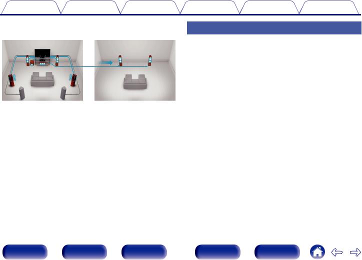
0 Multi-Room audio (v p. 117)
GMAIN ZONEH |
GZONE2H |
You can select and playback the respective inputs in the MAIN ZONE and in ZONE2.
In addition, when the All Zone Stereo function is used, the music being played back in the MAIN ZONE can be enjoyed in all the zones at the same time, which is useful when you want to hear BGM throughout the whole house.
0Energy-saving design
This unit is equipped with an ECO Mode function that allows you to enjoy music and movies while reducing the power consumption during use, and also an auto-standby function that automatically turns off the power supply when the unit is not in use. This helps reduce unnecessary power use.
Easy operation
0“Setup Assistant” provides easy-to-follow setup instructions
First select the language when prompted. Then simply follow the instructions displayed on the TV screen to set up the speakers, network, etc.
0Easy to use Graphical User Interface
This unit is equipped with a Graphical User Interface for improved operability.
Front panel |
Display |
Rear panel |
12 |
Remote |
Index |
Contents |
Connections |
Playback |
Settings |
Tips |
Appendix |
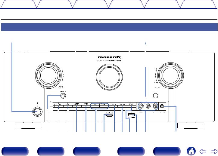
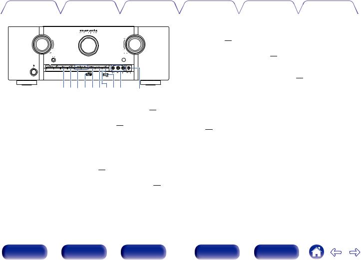
Part names and functions
Front panel
q w e |
|
|
r t |
y u |
|
|
i |
|||||||||||||||
|
|
|
|
|
|
|
||||||||||||||||
|
|
|
|
|
|
|
|
|
|
|
|
|
|
|
|
|
|
|
|
|
|
|
|
|
|
|
|
|
|
|
|
|
|
|
|
|
|
|
|
|
|
|
|
|
|
|
|
|
|
|
|
|
|
|
|
|
|
|
|
|
|
|
|
|
|
|
|
|
|
|
|
|
|
|
|
|
|
|
|
|
|
|
|
|
|
|
|
|
|
|
|
|
|
|
|
|
|
|
|
|
|
|
|
|
|
|
|
|
|
|
|
|
|
|
|
|
|
|
|
|
|
|
|
|
|
|
|
|
|
|
|
|
|
|
|
|
|
|
|
|
|
|
|
|
|
|
|
|
|
|
|
|
|
|
|
|
|
|
|
|
o |
Q0 Q1Q2 Q3 Q4Q5 Q6Q7Q8Q9W0 |
W1 |
Front panel |
Display |
Rear panel |
13 |
Remote |
Index |
Contents |
Connections |
Playback |
Settings |
Tips |
Appendix |
|
|
|
|
|
|
qwe |
|
|
|
|
|
|
r t |
|
y u |
|
|
|
i |
|
|||||||||||||||||||||
|
|
|
|
|
|
|
|
|
|
|
|
|
|
|
|
|
|
|
|
|
|
|
|
|
|
|
|
|
|
|
|
|
|
|
|
|
|
|
|
|
|
|
|
|
|
|
|
|
|
|
|
|
|
|
|
|
|
|
|
|
|
|
|
|
|
|
|
|
|
|
|
|
|
|
|
|
|
|
|
|
|
|
|
|
|
|
|
|
|
|
|
|
|
|
|
|
|
|
|
|
|
|
|
|
|
|
|
|
|
|
|
|
|
|
|
|
|
|
|
|
|
|
|
|
|
|
|
|
|
|
|
|
|
|
|
|
|
|
|
|
|
|
|
|
|
|
|
|
|
|
|
|
|
|
|
|
|
|
|
|
|
|
|
|
|
|
|
|
|
|
|
|
|
|
|
|
|
|
|
|
|
|
|
|
|
|
|
|
|
|
|
|
|
|
|
|
|
|
|
|
|
|
|
|
|
|
|
|
|
|
|
|
|
|
|
|
|
|
|
|
|
|
|
|
|
|
|
|
|
|
|
|
|
|
|
|
|
|
|
|
|
|
|
|
|
|
|
|
|
|
|
|
|
|
|
|
|
|
|
|
|
|
|
|
|
|
|
|
|
|
|
|
|
|
|
|
|
|
|
|
|
|
|
|
|
|
|
|
|
|
|
|
|
|
|
|
|
|
|
|
|
|
|
|
|
|
|
|
|
|
|
|
|
|
|
|
|
|
|
|
|
|
|
|
|
|
|
|
|
|
|
|
|
|
|
|
|
|
|
|
|
|
|
|
|
|
|
|
|
|
|
|
|
|
|
|
|
|
|
|
|
|
|
|
|
|
|
|
|
|
|
|
|
|
|
|
|
|
|
|
|
|
|
|
|
|
|
|
|
|
|
|
|
|
|
|
|
|
|
|
|
|
|
|
|
|
|
|
|
|
|
|
|
|
|
|
|
|
|
|
|
|
|
|
|
|
|
|
|
|
|
o Q0Q1
A Power operation button (X)
Used to turn the power of the MAIN ZONE (room where this unit is located) on/off (standby). (v p. 58)
B Power indicator
This is lit as follows according to the power status:
0Off: Power on
0Red: Normal standby
0Orange:
0 When “HDMI Pass Through” (v p. 166) is set to “On” 0 When “HDMI Control” (v p. 166) is set to “On”
0 When “IP Control” (v p. 200) is set to “Always On”
C INPUT SELECTOR knob
This selects the input source. (v p. 58)
D PURE DIRECT indicator
This lights when the “Pure Direct” mode is selected as the sound mode. (v p. 120)
E M-DAX indicator
This lights when the M-DAX mode is selected. (v p. 156)
FDisplay
This displays various pieces of information. (v p. 16)
G Remote control sensor
This receives signals from the remote control unit. (v p. 8)
H VOLUME knob
This adjusts the volume level. (v p. 59)
I Headphones jack (PHONES)
This is used to connect headphones.
When the headphones are plugged into this jack, audio will no longer be output from the connected speakers or from the PRE OUT connectors.
NOTE
To prevent hearing loss, do not raise the volume level excessively when using headphones.
J PURE DIRECT button
This switches the sound mode between Direct, Pure Direct and Auto surround. (v p. 120, 121)
K M-DAX button
This switches the M-DAX mode. (v p. 156)
Front panel |
Display |
Rear panel |
14 |
Remote |
Index |
Contents |
Connections |
Playback |
Settings |
Tips |
Appendix |
|
|
|
|
|
|
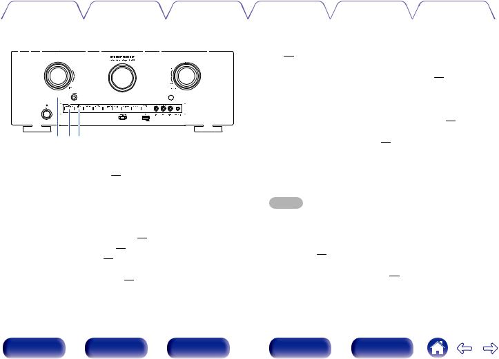
Q2Q3Q4Q5Q6Q8Q7Q9W0 W1
L ZONE2 ON/OFF button
This turns the power of ZONE2 (separate room) on/off. (v p. 143)
M ZONE2 SOURCE button
This selects the input source for ZONE2. (v p. 143)
N Tuner preset channel buttons
(TUNER PRESET CH +, –)
These select preset broadcast stations. (v p. 77)
O AUX1-HDMI connector
This is used to connect HDMI output compatible devices such as video camcorders and game consoles. (v p. 46)
P DIMMER button
Each press of this switches the brightness of the display. (v p. 207)
Q STATUS button
Each press of this switches the status information that is shown on the display. (v p. 62)
R SOUND MODE button
Switching the sound mode. (v p. 118)
S USB port
This is used to connect USB storages (such as USB memory devices) and the USB cable supplied with iPod. (v p. 48)
T AUX1 INPUT connectors
Used to connect devices such as a video camcorder or game console. (v p. 46)
Remove the cap covering the connectors when you want to use them.
U SETUP MIC jack
This is used to connect the supplied Sound calibration microphone. (v p. 181)
Front panel |
Display |
Rear panel |
15 |
Remote |
Index |
Contents |
Connections |
Playback |
Settings |
Tips |
Appendix |
|
|
|
|
|
|
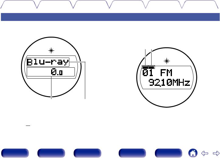
Display
The input source name, sound mode, setting values and other information are displayed here.
o Standard display
q w
A Volume indicator
B Input source indicator
The currently selected input source name is displayed.
If the input source name has been changed using “Source Rename” (v p. 176) in the menu, the input source name after the change is displayed.
o Tuner display
These light up according to the reception conditions when the input source is set to “Tuner”.
e r
C Lights up when the broadcast is properly tuned in.
D In the FM mode, this lights up when receiving stereo broadcasts.
Front panel |
Display |
Rear panel |
16 |
Remote |
Index |
Contents |
Connections |
Playback |
Settings |
Tips |
Appendix |
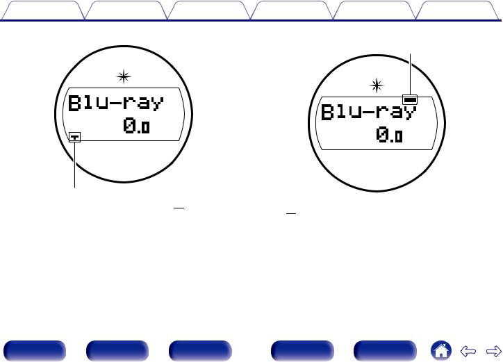
o Sleep timer indicator
t
E This lights when the sleep mode is selected. (v p. 131)
o ZONE2 power on display
y
F This lights up when ZONE2 (separate room) power is turned on. (v p. 143)
Front panel |
Display |
Rear panel |
17 |
Remote |
Index |

Contents |
Connections |
Playback |
Settings |
Tips |
Appendix |
|
|
|
|
|
|
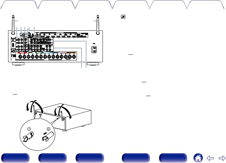
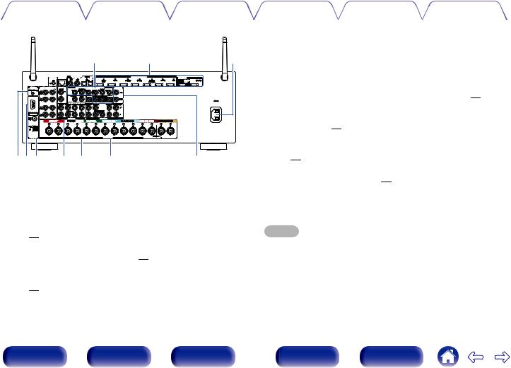
Rear panel
q w e r t |
y |
u |
i |
|
q |
o |
|
Q0Q1Q2 |
Q3 |
Q4 |
|
Q5 |
t |
Q6 |
|
Front panel |
Display |
Rear panel |
18 |
Remote |
Index |
Contents |
Connections |
Playback |
Settings |
Tips |
Appendix |
|
|
|
|
|
|
q |
q |
wer t y |
|
ty |
A Rod antennas for Bluetooth/wireless LAN
Stand this antenna upright when connecting to a network via wireless LAN, or when connecting to a handheld device via Bluetooth.
(v p. 53)
90°
90°
320°
320°
The antenna clip can be removed from the rear panel.
A Rotate the antenna clip 90 degrees to the left.
B Pull the antenna clip out towards yourself.
0The antenna clip is needed when transporting this unit. Keep it in a safe place.
0Attach the antenna clip by following the steps for removing it in reverse.
B Analog audio connectors (AUDIO)
Used to connect devices equipped with analog audio connectors. (v p. 44, 45)
C FLASHER IN jack
Used when using a control BOX or other such control devices to control this unit.
D NETWORK connector
Used to connect to a LAN cable when connecting to a wired LAN network. (v p. 52)
E PRE OUT connectors
Used to connect a subwoofer with built-in amplifier or power amplifier for ZONE2. (v p. 29, 142)
F Digital audio connectors (DIGITAL AUDIO)
Used to connect devices equipped with digital audio connectors. (v p. 41, 45)
Front panel |
Display |
Rear panel |
19 |
Remote |
Index |
Contents |
Connections |
Playback |
Settings |
Tips |
Appendix |
|
|
|
|
|
|
|
u |
i |
o |
Q0Q1Q2 |
Q3Q4 |
Q5 |
Q6 |
G Component video connectors (COMPONENT VIDEO)
Used to connect devices equipped with component video connectors. (v p. 44, 45)
H HDMI connectors
Used to connect devices equipped with HDMI connectors. (v p. 40, 41, 44, 45)
I AC inlet (AC IN)
Used to connect the power cord. (v p. 56)
J DC OUT jack
Used to connect devices equipped with the trigger function. (v p. 55)
K RS-232C connector
Used to connect home automation controller devices fitted with RS-232C connectors. Consult the owner’s manual of the home automation controller for more information about serial control of this unit.
L FM/AM antenna terminals (ANTENNA)
Used to connect FM antennas and AM loop antennas. (v p. 50)
M 7.1-channel input connectors (7.1CH IN)
Used to connect to a device that has multi-channel audio output connectors. (v p. 47)
N Video connectors (VIDEO)
Used to connect devices equipped with video connectors. (v p. 44, 45)
O Speaker terminals (SPEAKERS)
Used to connect speakers. (v p. 28)
P REMOTE CONTROL jacks
Used to connect infrared receivers/transmitters in order to operate this unit and external devices from a different room. (v p. 54)
NOTE
Do not touch the inner pins of the connectors on the rear panel. Electrostatic discharge may cause permanent damage to the unit.
Front panel |
Display |
Rear panel |
20 |
Remote |
Index |
Contents |
Connections |
Playback |
Settings |
Tips |
Appendix |
|
|
|
|
|
|
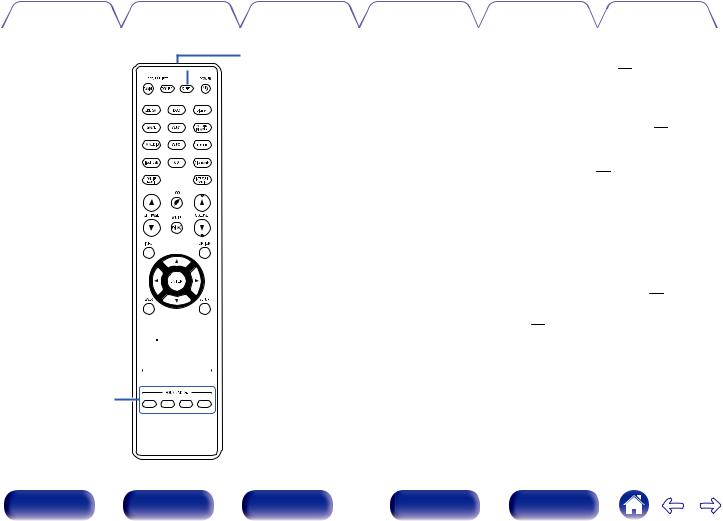
Remote control unit
q


w


e


r


t
 y
y


u

A ZONE SELECT buttons (MAIN, ZONE2)
These switch the zone (MAIN ZONE, ZONE2) that is operated through the remote control unit. (v p. 143, 148)
B Input source select buttons
These selects the input source. (v p. 58, 143)
C Channel/page select buttons (CH/PAGE df)
These select radio stations registered to presets or switch pages. (v p. 62, 77)
D MUTE button (:)
This mutes the output audio. (v p. 59, 144)
E Information button (INFO)
This displays the status information on the TV screen. (v p. 209)
F Cursor buttons (uio p)
These select items. (v p. 148)
G BACK button
This returns to the previous screen. (v p. 148)
Front panel |
Display |
Rear panel |
21 |
Remote |
Index |
Contents |
Connections |
Playback |
Settings |
Tips |
Appendix |
|
|
|
|
|
|
Q1
 Q2
Q2
i
 o
o


 Q0
Q0 


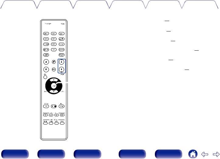
H System buttons
These perform playback related operations. (v p. 62)
0Skip buttons (8, 9)
0Play/pause button (1/3)
Tuning up / Tuning down buttons (TUNE +, –)
These select either FM broadcast or AM broadcast. (v p. 74)
I SMART SELECT buttons (1 – 4)
These call up settings registered to each button, such as input source, volume level and sound mode settings. (v p. 133)
J SOUND MODE buttons
These select the sound mode. (v p. 118)
0MOVIE button
0MUSIC button
0GAME button
0PURE button
K Remote control signal transmitter
This transmits signals from the remote control unit. (v p. 8)
L SLEEP button
This sets the sleep timer. (v p. 131)
Front panel |
Display |
Rear panel |
22 |
Remote |
Index |
Contents |
Connections |
Playback |
Settings |
Tips |
Appendix |
|
|
|
|
|
|


 Q3
Q3

 Q4
Q4 


 Q5
Q5

 Q6
Q6

 Q7
Q7 

 Q8
Q8
M POWER button (X)
This turns the power on/off. (v p. 58, 143)
NECO Mode button (G)
This switches to ECO Mode. (v p. 203)
O VOLUME buttons (df)
These adjusts the volume level. (v p. 59, 144)
P OPTION button
This displays the option menu on the TV screen. (v p. 107)
Q ENTER button
This determines the selection. (v p. 148)
R SETUP button
This displays the menu on the TV screen. (v p. 148)
Front panel |
Display |
Rear panel |
23 |
Remote |
Index |
Contents |
Connections |
Playback |
Settings |
Tips |
Appendix |
o Contents
Connecting speakers |
25 |
Connecting a TV |
39 |
Connecting a playback device |
43 |
Connecting an iPod or USB memory device to the USB port |
48 |
Connecting an FM/AM antenna |
50 |
Connecting to a home network (LAN) |
52 |
Connecting an external control device |
54 |
Connecting the power cord |
56 |
NOTE
0Do not plug in the power cord until all connections have been completed. However, when the “Setup Assistant” is running, follow the instructions in the “Setup Assistant” (page 8 in the separate “Quick Start Guide”) screen for making connections. (During “Setup Assistant” operation, the input/output connectors do not conduct current.)
0Do not bundle power cords together with connection cables. Doing so can result in noise.
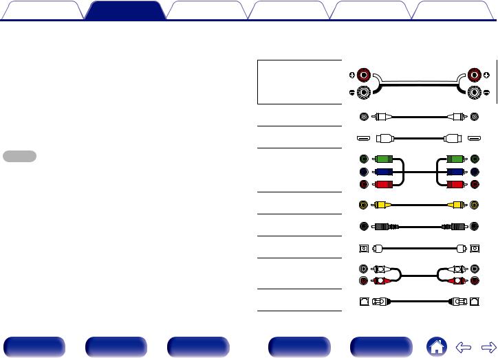
o Cables used for connections
Provide necessary cables according to the devices you want to connect.
Speaker cable
Subwoofer cable
HDMI cable
Component video cable
Video cable
Coaxial digital cable
Optical cable
Audio cable |
L |
L |
|
R |
R |
||
|
LAN cable
Front panel |
Display |
Rear panel |
24 |
Remote |
Index |
Contents |
Connections |
Playback |
Settings |
Tips |
Appendix |
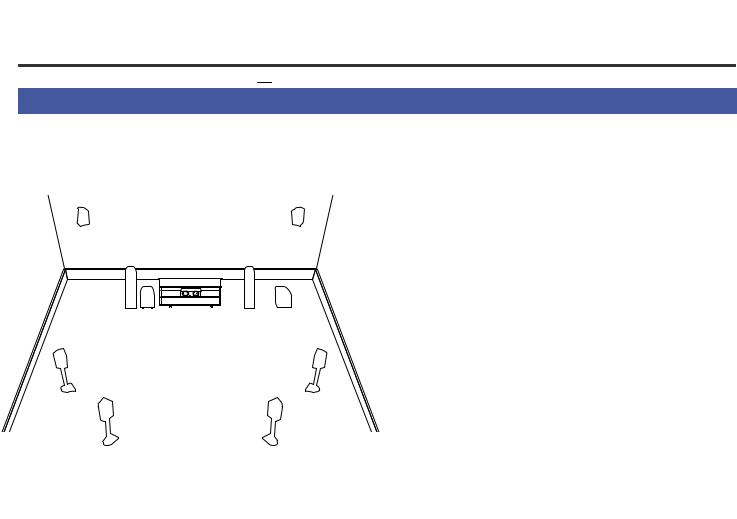
Connecting speakers
Install speakers and connect them to this unit. (v p. 25, 28)
Speaker installation
Determine the speaker system depending on the number of speakers you are using and install each speaker and subwoofer in the room.
Speaker installation is explained using this example of a typical installation.
FHL |
|
FHR |
FL |
|
FR |
SW1 C |
|
SW2 |
SL |
|
SR |
SBL |
SB |
SBR |
|
|
FL/FR (Front |
Place the FRONT left and right speakers an |
|
equal distance from the main listening position. |
||
speaker left/right): |
The distance between each speaker and your TV |
|
|
should also be the same. |
|
C (Center |
Place the CENTER speaker in front of and at the |
|
center of the TV, between the front left and right |
||
speaker): |
||
speakers. |
||
|
||
|
Place the SURROUND left and right speakers an |
|
SL/SR (Surround |
equal distance to the left and right sides of the |
|
main listening position. If you don’t have |
||
speaker left/right): |
||
surround back speakers, move the surround |
||
|
speakers slightly behind your listening position. |
|
|
Place the SURROUND BACK left and right |
|
SBL/SBR |
speakers an equal distance from the main |
|
listening position and directly behind the main |
||
(Surround back |
||
listening position. When using a single surround |
||
speaker left/right): |
||
back speaker (SB), place it directly behind the |
||
|
listening position. |
|
FHL/FHR (Front |
Place the FRONT HEIGHT left and right |
|
speakers just outside of the front left and right |
||
height speakers |
speakers. Mount them as close to the ceiling as |
|
left/right): |
possible and aim them towards the listening |
|
|
position. |
|
SW 1/2 (Subwoofer) : |
Place the SUBWOOFER at a convenient location |
|
near the front speakers. |
Front panel |
Display |
Rear panel |
25 |
Remote |
Index |
Contents |
Connections |
Playback |
Settings |
Tips |
Appendix |
|
|
|
|
|
|
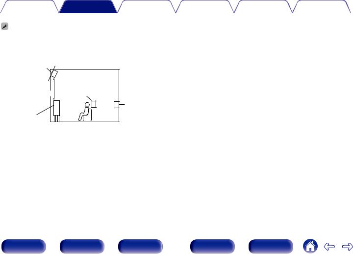
0This unit is compatible with Dolby Pro Logic gz (v p. 252) which offers an even wider and deeper surround sensation.
When using Dolby Pro Logic gz, install front height speakers.
0Use the illustration below as a guide for how high each speaker should be installed. The height does not need to be exactly the same.
Front height |
|
|
speaker |
|
|
Point slightly |
|
Surround |
downwards |
|
|
At least 3.3 ft / 1 m |
z |
speaker |
|
Surround back |
|
|
|
speaker |
Front speaker |
|
|
|
|
GViewed from the sideH |
z Recommended for Dolby Pro Logic gz |
||
Front panel |
Display |
Rear panel |
26 |
Remote |
Index |
Contents |
Connections |
Playback |
Settings |
Tips |
Appendix |
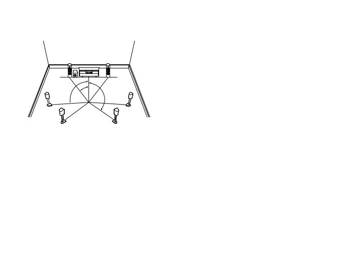
oWhen 7.1-channel speakers are installed using surround back speakers
FL |
FR |
SW |
C |
|
z1 |
z2 |
z3 |
|
 SL
SL 
 SR
SR
|
Listening |
|
SBL |
position |
SBR |
|
z1:22° - 30° z2:90° - 110° z3:135° - 150°
When using a single surround back speaker, place it directly behind the listening position.
oWhen 7.1-channel speakers are installed using front height speakers
FHL |
FHR |
FL |
FR |
SWz2 |
C |
z1 |
|
|
z3 |
SL |
SR |
z1:22° - 30° z2:22° - 45° z3:90° - 110°
o When 5.1-channel speakers are installed
FL |
|
FR |
SW |
C |
z1 |
z2 |
|
|
SL |
SR |
z1:22° - 30° z2:120°
Front panel |
Display |
Rear panel |
27 |
Remote |
Index |
Contents |
Connections |
Playback |
Settings |
Tips |
Appendix |
|
|
|
|
|
|
Speaker connection
Here we connect the speakers in the room to this unit.
This section explains how to connect them using typical examples.
NOTE
0Disconnect this unit’s power plug from the power outlet before connecting the speakers. Also, turn off the subwoofer.
0Connect so that the speaker cable core wires do not protrude from the speaker terminal. The protection circuit may be activated if the core wires touch the rear panel or if the + and - sides touch each other. (“Protection circuit” (v p. 259))
0Never touch the speaker terminals while the power cord is connected. Doing so could result in electric shock. When the “Setup Assistant” (page 8 in the separate “Quick Start Guide”) is running, follow the instructions in the “Setup Assistant” screen for making connections. (Power is not supplied to the speaker terminals while the “Setup Assistant” is running.)
0Use speakers with an impedance of 4 – 16 Ω/ohms.
NOTE
0Carry out the following settings when using a speaker with an impedance of 4 – 6 Ω/ohms.
1.Press and hold the main unit’s ZONE2 SOURCE and STATUS for at least 3 seconds.
“Video Format < NTSC>” appears on the display.
2.Press DIMMER on the main unit twice. “Sp.Imp. <8ohms>” appears on the display.
3.Press TUNER PRESET CH + or TUNER PRESET CH on the main unit to select the impedance.
6 Ω: |
6 Ω/ohms to 8 Ω/ohms is selected even if it is for one speaker with a |
|
connected impedance. |
||
|
||
4 Ω: |
4 Ω/ohms to 8 Ω/ohms is selected even if it is for one speaker with a |
|
connected impedance. |
||
|
4. Press the main unit’s STATUS to complete the setting.
Front panel |
Display |
Rear panel |
28 |
Remote |
Index |
Contents |
Connections |
Playback |
Settings |
Tips |
Appendix |
o Connecting the speaker cables
Carefully check the left (L) and right (R) channels and + (red) and – (black) polarities on the speakers being connected to this unit, and be sure to connect the channels and polarities correctly.
1Peel off about 3/8 inch (10 mm) of sheathing from the tip of the speaker cable, then either twist the core wire tightly or terminate it.
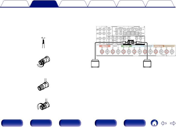
o Connecting the subwoofer
Use a subwoofer cable to connect the subwoofer. Two subwoofers can be connected to this unit.
The same signal is output from the respective subwoofer terminals.
2 |
Turn the speaker terminal counterclockwise to loosen it. |
|
3 |
SW1 |
SW2 |
Insert the speaker cable’s core wire to the hilt into the |
|
|
speaker terminal. |
|
4Turn the speaker terminal clockwise to tighten it.
Front panel |
Display |
Rear panel |
29 |
Remote |
Index |
Contents |
Connections |
Playback |
Settings |
Tips |
Appendix |
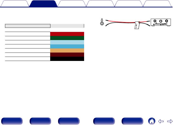
oAbout the speaker cable label (supplied) for channel identification
The channel display section for speaker terminals on the rear panel is color-coded for each channel to be identifiable.
Speaker terminals |
Color |
FRONT L |
White |
FRONT R |
Red |
CENTER |
Green |
SURROUND L |
Light blue |
SURROUND R |
Blue |
SURROUND BACK L |
Beige |
SURROUND BACK R |
Brown |
SUBWOOFER |
Black |
Attach the speaker cable label for each channel to its speaker cable as shown in the diagram.
Refer to the table above and attach the label to each speaker cable.
Then, make connection so that the color of the speaker terminal matches that of the speaker cable label.
G How to attach the speaker cable label H
Speaker |
This unit |
||||||
|
|
|
|
|
|
|
|
|
|
|
|
|
|
|
|
|
|
|
|
|
|
|
|
|
|
|
|
|
|
|
|
Front panel |
Display |
Rear panel |
30 |
Remote |
Index |
Loading...