


R
Model SR-14EX User Guide
AV Surround Receiver

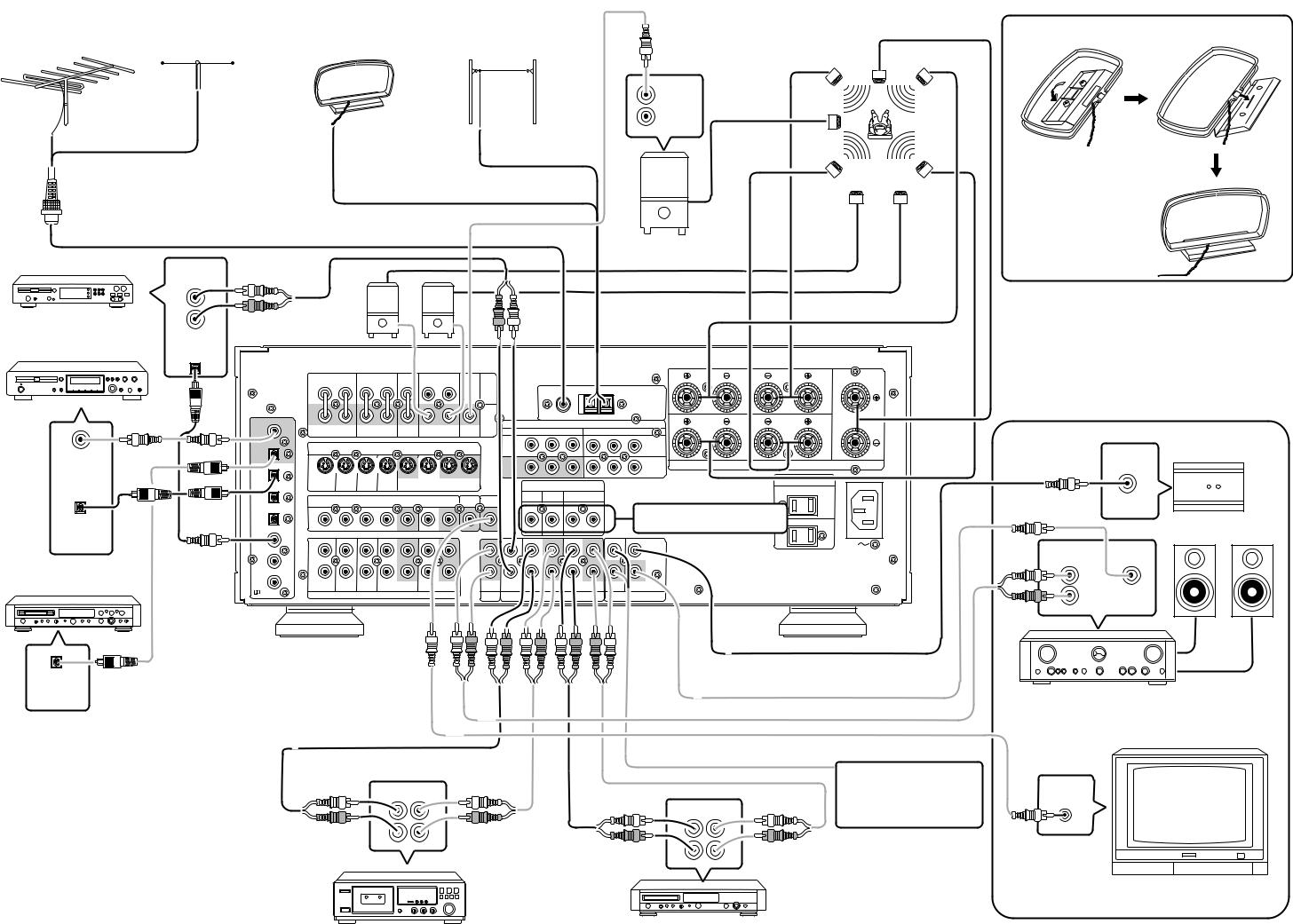
VIDEO SYSTEM CONNECTIONS FOR VIDEO COMPONENTS
|
|
|
MONITOR TV |
|
|
|
|
|
LD PLAYER |
|
DVD PLAYER, |
|
|
|
S-VIDEO VIDEO COMPONENT |
||
RF |
AUDIO VIDEO S-VIDEO |
COMPONENT SATELLITE TUNER or VCR |
|||
IN |
IN VIDEOCb Cr IN |
VIDEOCb CrOUT |
|||
OUT |
OUT OUT |
OUT |
|
Y Cb Cr |
Y Cb Cr |
L R
(FRONT AUX CONNECTIONS)
TV
AUDIO VIDEO S-VIDEO
OUT OUT |
OUT |
L R |
|
|
|
FRONT |
SURROUND |
|
|
(FRONT) |
|
|
|
|
|
R |
FRONT |
L |
|
|
|
L |
R |
L |
R |
|
L |
R |
|
|
|
|
|
|
|
|
|
|
|
|
|
|
|
|
|
|
MAIN |
FM (75Ω ) |
GND |
AM |
|
|
|
|
|
|
|
|
|
|
|
|
|
|
|
|
ANTENNA |
|
|
|
|
|
|
|
|
|
|
|
|
|
IN |
|
|
|
|
|
|
|
|
|
|
|
|
|
|
|
|
|
|
|
|
|
|
|
|
|
|
|
|
|
|
|
|
|
|
|
|
|
ANTENNA |
|
|
|
|
|
|
|
|
|
|
|
|
PRE |
|
|
|
|
|
|
|
|
|
|
|
|
|
|
|
|
OUT |
COMPONENT VIDEO |
R |
SURROUND |
L |
CENTER |
||
COAX |
|
|
|
|
|
|
|
|
|
Cr |
|
|
||||
OUT |
L |
R |
L |
R |
|
L |
R |
|
|
COMPONENT VIDEO |
Cr |
|
|
|
||
|
SUB |
Y |
Cr |
Y |
|
Cr |
|
|
|
|||||||
|
|
FRONT |
SURROUND |
CENTER |
SURROUND BACK WOOFER |
|
|
|
|
|||||||
|
|
|
|
|
|
|
|
|
|
|||||||
S - VIDEO |
VCR1 |
DVD |
|
S - VIDEO |
|||
IN |
IN |
||
OPT |
|
|
OUT |
|
|
|
|
|
|
|
DSS |
SPEAKER |
SYSTEMS |
8 OHMS |
|
|
|
|
|
|
|
|
MONITOR |
SPEAKER |
SYSTEMS |
8 OHMS |
|
|
|
|
|
|
|
|
|
/ VCR2 |
|
||||
|
|
|
|
|
|
|
OUT |
|
AC OUTLETS |
|
||
DIG .1 |
|
|
|
|
|
|
IN |
|
|
|||
|
|
|
|
|
|
|
|
120V 60HZ |
|
|||
IN |
|
|
|
|
|
|
|
|
|
AC INLET |
||
TV |
LD |
DVD |
VCR1 |
VCR1 |
DSS / VCR2 DSS / VCR2 |
MONI. |
|
|
SWITCHED 120W 1A |
|
||
S2 IN |
S2 IN |
S2 IN |
S2 IN |
OUT |
S2 IN |
|
S2 OUT |
|
|
|
||
|
|
|
|
|
|
OUT |
|
DIRECT IN |
|
|
120V 60HZ |
|
DIG .2 |
|
|
VIDEO |
|
|
|
|
|
|
|
SUB |
|
|
|
SWITCHED 120W 1A |
|
|
|
|
|
|
|
|
MULTI |
|
CENTER WOOFER |
SURROUND |
|
|
||
IN |
|
|
VIDEO |
|
|
|
MONI. |
|
|
|
|||||
|
|
|
|
|
|
|
|
|
ROOM |
|
|
|
|
|
|
DIG .3 |
|
|
|
|
|
|
|
|
|
|
|
|
|
|
UNSWITCHED 120W 1A |
IN |
|
|
|
|
|
|
|
|
|
|
|
|
|
|
UNSWITCHED 120W 1A |
DIG .4 |
|
|
|
|
|
|
|
|
|
|
|
L |
R |
|
|
IN |
|
|
|
|
|
|
|
|
|
|
|
|
|
|
|
DIG .5 |
L |
|
|
|
|
|
|
|
|
|
|
|
|
|
IN |
IN |
|
|
|
|
|
|
|
|
|
|
|
|
|
|
OUT |
|
|
|
|
|
|
|
|
|
|
|
|
|
|
|
|
|
|
|
|
|
|
|
|
|
|
|
|
|
|
|
OUT |
|
R |
|
|
|
|
|
|
|
|
|
|
|
|
|
|
DIG .6 |
|
|
|
– |
– |
IN |
DSS/VCR2 OUT |
AUDIO |
|
|
CD-R / MD |
OUT |
|
|
|
/ |
TV |
LD |
DVD |
IN – VCR1 – OUT |
IN – DSS/VCR2 – OUT |
|
AUDIO |
CD |
IN – TAPE – OUT |
IN – CD-R / MD – OUT |
REMOTE |
MULTI |
|||
|
|
|
AUDIO |
|
|
|
|
|
MULTI |
|
AUDIO |
|
REMOTE CONTROL |
||
RF IN |
|
|
AUDIO |
|
|
|
|
|
AUDIO |
|
|
REMOTE CONTROL |
|||
|
|
|
|
|
|
|
|
ROOM |
|
|
|
|
|
|
|
AUX INPUT
S2-VIDEO |
VIDEO L AUDIO R |
|||||||||||||||
|
|
|
|
|
|
|
|
|
|
|
|
|
|
|
|
|
|
|
|
|
|
|
|
|
|
|
|
|
|
|
|
|
|
|
|
|
|
|
|
|
|
|
|
|
|
|
|
|
|
|
|
|
|
|
|
|
|
|
|
|
|
|
|
|
|
|
|
|
|
|
|
|
|
|
|
|
|
|
|
|
|
|
|
|
|
|
|
|
|
|
|
|
|
|
|
|
|
|
|
|
|
|
|
|
|
|
|
|
|
|
|
|
|
|
|
|
|
|
|
|
|
|
|
|
|
|
|
|
|
|
|
|
|
|
|
|
|
|
|
|
|
|
|
|
|
|
|
|
|
|
|
|
|
|
|
|
|
|
|
|
|
|
|
|
|
|
|
|
|
|
|
|
|
|
|
|
|
|
|
|
|
|
|
|
|
|
|
|
|
|
|
|
|
|
|
|
|
|
|
|
|
|
|
|
|
|
|
|
|
|
|
|
|
|
|
|
|
|
|
|
|
|
|
|
|
|
|
|
|
|
|
|
|
|
|
|
|
VIDEO AUDIO
OUT OUT
L

R 
VIDEO CAMERA
To household power outlet
Connect the provided detachable power cord
DIGITAL AUDIO |
VIDEO S-VIDEO |
|
|
|
|
|
OUT OUT |
OUT |
OUT |
|
|
|
|
L R |
|
|
|
|
|
|
|
|
AUDIO AUDIO VIDEO S-VIDEO |
|
|
|
|
|
|
OUT |
IN OUT IN OUT IN |
|
|
|
|
|
|
DIGITAL AUDIO AUDIO VIDEO S-VIDEO |
|
||
|
|
|
OUT |
OUT |
IN OUT IN OUT IN |
|
|
|
L R |
L R |
|
|
|
DVD PLAYER |
|
VCR |
L R |
L R |
SATELLITE TUNER or VCR2 |
|
|
|
|
|
|||
i
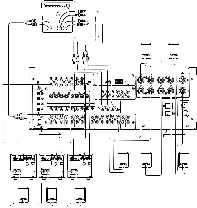
AUDIO SYSTEM CONNECTIONS FOR AUDIO COMPONENTS |
SUBWOOFER |
|
SPEAKER |
|
|
|
SYSTEM |
||
FM EXTERNAL ANTENNA FM FEEDER ANTENNA AM LOOP ANTENNA AM EXTERNAL ANTENNA |
AMPLIFIER |
|
|
|
MA6100 |
|
|
CENTER SPEAKER |
|
|
NORMAL |
|
Left |
Right |
|
INPUT |
|
|
|
|
INVERT |
SUBWOOFER |
|
|
|
OUTPUT |
|
|
|
¥ When using the FM antenna |
Surround |
Surround |
|
attach to this apparatus |
Left |
Right |
|
Surround |
Surround |
||
|
|||
|
Back Left |
Back Right |
Assemble the AM loop antenna as shown in the figure before use
CD PLAYER
OUTPUT |
|
|
L |
SURROUND SPEAKER |
|
R |
||
Suuround Back |
||
|
AMPLIFIER |
CD Recorder |
DIGITAL |
MA6100 |
|
|
|
|
|
|
|
|
|
|
|
|
|
|
|
|
|
|
|
|
|
|
|
OUTPUT |
|
|
|
|
|
|
|
|
|
|
|
|
|
|
|
|
|
|
|
|
|
|
|
|
|
|
|
FRONT |
|
SURROUND |
|
(FRONT) |
|
|
|
|
|
|
|
|
|
|
|
|
|
FRONT |
|
|
|
|
|
|
|
FRONT |
SURROUND |
|
(FRONT) |
|
|
|
|
|
|
|
|
|
|
|
R |
FRONT |
L |
|
|
|
|||
|
|
L |
R |
L |
R |
|
L |
R |
|
|
|
|
FM (75 |
|
GND |
AM |
|
|
|
|
|
|
|
||
|
|
|
|
|
|
|
|
|
|
|
MAIN |
|
|
FM (75Ω ) |
GND |
AM |
|
|
|
|
|
|
|
||
|
|
|
|
|
|
|
|
|
|
|
|
|
|
|
|
|
ANTENNA |
|
|
|
|
|
|
||
|
|
|
|
|
|
|
|
|
|
|
IN |
|
|
|
|
|
|
|
|
|
|
|
|
||
|
|
|
|
|
|
|
|
|
|
|
|
|
|
|
|
|
|
|
|
|
|
|
|
|
|
|
|
|
|
|
|
|
|
|
|
|
PRE |
|
|
|
|
|
|
|
ANTENNA |
|
|
|
|
|
|
|
COAX |
|
|
|
|
|
|
|
|
|
PRE |
|
|
|
|
|
|
|
|
SURROUND |
|
|
|
|
|
|
|
|
|
|
|
|
|
|
|
OUT |
|
|
COMPONENT VIDEO |
|
|
CENTER |
|
|
|||||||
|
|
|
|
|
|
|
|
|
|
|
|
|
R |
|
L |
|
|
||||||||
|
OUT |
|
|
|
|
|
|
|
SUB |
|
|
|
Cr |
|
|
|
|
SURROUND |
|
|
|||||
|
COAX |
|
|
|
|
|
|
|
|
|
|
|
|
|
|
|
Cr |
|
|
|
|
|
|
||
|
OUT |
FRONT |
R |
SURROUND |
CENTER |
SURROUND BACK |
WOOFER |
|
|
|
COMPONENT VIDEO |
|
|
|
|
|
|
||||||||
|
L |
L |
R |
|
L |
R |
|
SUB |
|
|
Y |
|
|
Cr |
Y |
|
Cr |
|
|
|
|
|
|
||
|
|
FRONT |
|
SURROUND |
CENTER |
SURROUND BACK WOOFER |
|
|
|
|
|
|
|
|
|
|
|||||||||
|
|
|
|
|
|
|
|
|
|
|
|
|
|
|
|||||||||||
|
|
|
|
|
|
|
|
|
|
|
|
|
|
|
|
|
|||||||||
|
OPT |
|
|
S - VIDEO |
|
|
|
|
|
|
VCR1 |
|
|
|
|
|
|
DVD |
|
|
|
|
|
|
|
|
|
|
S - VIDEO |
|
|
|
|
|
|
|
|
|
|
|
|
|
|
|
|
MULTI |
IR RECEIVER |
||||
|
OUT |
|
|
|
|
|
|
|
|
IN |
|
|
|
|
|
|
IN |
|
|
|
|
||||
|
OUT |
|
|
|
|
|
|
|
|
|
|
|
|
|
|
|
|
|
|
|
|
|
|
||
|
OPT |
|
|
|
|
|
|
|
|
|
|
|
|
|
|
|
|
|
|
SPEAKER |
SYSTEMS |
8 OHMS |
|
|
|
DIGITAL |
DIG .1 |
|
|
|
|
|
|
|
|
|
|
MONITOR |
|
|
|
|
|
|
/ VCR2 |
|
ROOM |
|
|||
|
|
|
|
|
|
|
|
|
|
|
|
|
|
|
|
SPEAKER |
SYSTEMS |
8 OHMS |
|
||||||
INPUT |
|
|
|
|
|
|
|
|
|
|
|
|
|
|
|
|
|
|
DSS |
|
|
|
|
|
|
IN |
|
|
|
|
OUT |
|
|
|
|
|
OUT |
|
|
|
|
|
|
|
|
120VAC60HZOUTLETS |
AC INLET |
|
|
||
|
DIG .1 |
|
|
|
VCR1 |
VCR1 DSS / VCR2 DSS / VCR2 |
MONI. |
|
|
|
|
|
|
|
IN |
|
AC OUTLETS |
AC INLET |
|
|
|||||
|
|
TV |
LD |
DVD |
VCR1 |
VCR1 |
DSS / VCR2OUTDSS / VCR2 |
MONI. |
|
|
|
|
|
|
|
|
|
|
|
120V 60HZ |
|
|
|
||
|
|
S2 IN |
S2 IN |
S2 IN |
S2 IN |
OUT |
S2 IN |
|
|
S2 OUT |
|
|
|
|
|
|
|
|
|
|
|
|
|
||
|
DIG .2 |
OUT |
|
|
|
DIRECT IN |
|
|
|
|
SWITCHED 120W 1A |
|
|
|
|||||||||||
|
|
|
|
|
|
|
|
|
|
|
|
|
|
|
|
SWITCHED 120W 1A |
|
|
|
||||||
|
|
|
VIDEO |
|
|
|
|
|
|
|
|
SUB |
|
|
|
|
|
|
|
|
|
||||
|
DIG .2 |
|
|
|
|
|
|
|
ROOM |
|
CENTER |
|
SURROUND |
|
|
|
|
|
|
|
|
||||
|
IN |
|
|
VIDEO |
|
|
|
|
MONI. |
MULTI |
|
|
WOOFER |
|
|
|
|
|
|
|
|
|
|
|
|
|
|
|
|
|
|
|
ROOM |
|
|
|
|
|
|
|
|
|
|
|
|
INPUT |
|
||||
|
|
|
|
|
|
|
|
|
|
|
|
|
|
|
|
|
|
|
|
|
|
|
|
||
|
DIG .3 |
|
|
|
|
|
|
|
|
|
|
|
|
|
|
|
|
|
Refer to OTHER CONNECTIONS |
|
|
|
|||
|
DIG .3 |
|
|
|
|
|
|
|
|
|
|
|
|
|
|
|
|
|
(Page iii) |
UNSWITCHED 120W 1A |
|
|
|
||
|
IN |
|
|
|
|
|
|
|
|
|
|
|
|
|
|
|
|
|
UNSWITCHED 120W 1A |
|
|
MULTI ROOM SPEAKER |
|||
DIGITAL |
DIG .4 |
|
|
|
|
|
|
|
|
|
|
|
|
|
|
L |
R |
|
|
|
|
|
|||
|
|
|
|
|
|
|
|
|
|
|
|
|
|
|
|
|
|
|
|
|
|||||
IN |
|
|
|
|
|
|
|
|
|
|
|
|
|
|
|
|
|
|
|
|
|
||||
|
DIG .4 |
|
|
|
|
|
|
|
|
|
|
|
|
|
|
|
|
|
|
|
|
|
|
|
|
OUTPUT |
DIG .5 |
|
|
|
|
|
|
|
|
|
|
|
|
|
|
|
|
|
IN |
|
|
|
LINE IN |
RC IN |
|
|
IN |
L |
|
|
|
|
|
|
|
|
|
|
|
|
|
|
|
|
|
|
|
|
|||
|
DIG .5 |
|
|
|
|
|
|
|
|
|
|
|
|
|
|
|
|
|
|
|
|
|
|
||
|
|
|
|
|
|
|
|
|
|
|
|
|
|
|
|
|
|
|
OUT |
|
|
|
|
|
|
|
|
|
|
|
|
|
|
|
|
|
|
|
|
|
|
|
|
|
OUT |
|
|
|
|
|
|
|
DIG .6 |
R |
|
|
|
|
|
|
|
|
|
|
|
|
|
|
|
|
|
|
|
|
L |
|
|
MD PLAYER |
|
|
|
|
|
|
|
|
|
|
|
|
|
|
|
|
|
|
|
|
|
|
|
||
/ |
TV |
LD |
DVD |
IN – VCR1 – OUT |
IN – DSS/VCR2 – OUT |
|
AUDIO |
CD |
IN – TAPE – OUT |
IN – CD-R / MD – OUT REMOTE |
MULTI |
|
|
|
|
|
|||||||||
|
DIG .6 |
|
|
|
|
IN DSS/VCR2 |
OUT |
|
|
|
IN |
APE |
|
CD-R / MD |
OUT |
REMOTE |
|
|
|
|
|
|
|||
|
RF IN |
|
|
AUDIO |
|
|
|
|
|
ROOM |
|
AUDIO |
|
|
|
REMOTE CONTROL |
|
|
|
R |
|
|
|||
|
RF IN |
|
|
AUDIO |
|
|
|
|
|
MULTI |
|
|
AUDIO |
|
|
|
REMOTE CONTROL |
|
|
|
|
|
|||
|
|
|
|
|
|
|
|
|
|
ROOM |
|
|
|
|
|
|
|
|
|
|
|
|
|
||
(L) (R)
DIGITAL
INPUT MAIN AMP (For MULTI ROOM)
MONITOR TV for MULTI ROOM
|
|
|
To a component with REMOTE |
VIDEO |
OUT IN |
|
|
(Marantz RC-5 D-BUS) jacks |
|
|
|
Refer to OTHER CONNECTIONS |
IN |
|
L |
L |
OUT IN |
|
|
(Page iii) |
|
|||
R |
R |
L |
L |
|
|
|
|
||
|
|
R |
R |
|
TAPE DECK |
CD RECORDER/MD PLAYER |
MULTI ROOM
ii
OTHER CONNECTIONS
(Connectio with external 3ch amplifiers for Front+L, Front+R and subwoofer)
OTHER MULTI CHANNEL PROCESSOR
L  C
C
 LS
LS
R  SW
SW 
 RS
RS
Surround Back |
Surround Back |
||||||||
(R) speaker |
(L) speaker |
||||||||
|
|
|
|
|
|
|
|
|
|
|
|
|
|
|
|
|
|
|
|
|
|
|
|
|
|
|
|
|
|
|
|
|
|
|
|
|
|
|
|
FRONT |
|
SURROUND |
|
(FRONT) |
R |
FRONT |
L |
|
L |
R |
L |
R |
L |
R |
|
(SURR. BACK) |
|
|
|
|
|
|
|
|
|
|
MAIN |
FM (75Ω ) |
|
GND |
AM |
|
|
|
|
|
|
|
|
|
|
|
|
|
|
|
|
|
|
|
|
|
|
|
|
|
|
|
|
|
IN |
|
|
|
|
|
|
|
|
|
|
|
|
|
|
|
|
|
|
|
|
ANTENNA |
|
|
|
|
|
|
|
|
|
|
|
|
PRE |
|
|
|
R |
SURROUND |
L |
CENTER |
|
|
|
|
|
|
|
|
|
OUT |
|
|
|
||||
COAX |
|
|
|
|
|
|
|
|
|
COMPONENT VIDEO |
|
|
|
|||
OUT |
L |
R |
L |
R |
|
L |
R |
SUB |
Y |
|
Cr |
Y |
Cr |
|
|
|
|
|
FRONT |
SURROUND |
CENTER |
SURROUND BACK WOOFER |
|
|
|
|
|
|
|||||
|
|
|
S - VIDEO |
|
|
|
|
VCR1 |
|
|
|
DVD |
|
|
|
|
OPT |
|
|
|
|
|
|
IN |
|
|
|
IN |
|
|
|
||
|
|
|
|
|
|
|
|
|
|
|
|
|
|
|||
|
|
|
|
|
|
|
|
|
|
|
|
|
|
|
|
|
OUT |
|
|
|
|
|
|
|
|
|
|
|
|
|
|
|
|
|
|
|
|
|
|
|
|
MONITOR |
|
|
DSS |
S PEAKER |
SYSTEMS |
8 OHMS |
|
|
|
|
|
|
|
|
|
|
|
/ VCR2 |
|
||||
DIG .1 |
|
|
|
|
|
|
|
OUT |
|
|
IN |
|
|
|
|
|
|
|
|
|
|
|
|
|
|
|
|
|
|
||
IN |
TV |
LD |
DVD |
VCR1 |
VCR1 |
DSS / VCR2 DSS / VCR2 |
MONI. |
|
|
|
|
|
AC OUTLETS |
AC INLET |
|
|
|
|
|
|
|
|
120V 60HZ |
|
|||||||
|
S2 IN |
S2 IN |
S2 IN |
S2 IN |
OUT |
S2 IN OUT |
S2 OUT |
|
DIRECT IN |
|
|
|
|
||
|
|
|
|
SWITCHED 120W 1A |
|
||||||||||
DIG .2 |
|
|
|
|
|
|
|
|
SUB |
|
|
|
|
||
|
|
|
|
|
|
|
|
SURROUND |
|
|
|
|
|||
IN |
|
|
VIDEO |
|
|
MONI. |
MULTI |
CENTER WOOFER |
|
|
|
|
|||
|
|
|
|
ROOM |
|
|
|
|
|
|
|
||||
|
|
|
|
|
|
|
|
|
|
|
|
|
|
|
|
DIG .3 |
|
|
|
|
|
|
|
|
|
|
|
|
|
|
|
IN |
|
|
|
|
|
|
|
|
|
|
R |
|
UNSWITCHED 120W 1A |
|
|
DIG .4 |
|
|
|
|
|
|
|
|
|
L |
|
|
|
|
|
IN |
|
|
|
|
|
|
|
|
|
|
|
|
|
||
DIG .5 |
L |
|
|
|
|
|
|
|
|
|
IN |
|
|
|
|
IN |
|
|
|
|
|
|
|
|
|
|
|
|
|
|
|
|
|
|
|
|
|
|
|
|
|
|
OUT |
|
|
|
|
|
R |
|
|
|
|
|
|
|
|
|
|
|
|
|
|
DIG .6 |
|
|
|
|
|
|
|
|
|
|
|
|
|
|
|
/ |
TV |
LD |
DVD |
IN – VCR1 – OUT |
IN – DSS/VCR2 – OUT |
|
AUDIO CD |
IN – TAPE – OUT |
IN – CD-R / MD – OUT REMOTE MULTI |
|
|
|
|
||
RF IN |
|
|
AUDIO |
|
|
|
MULTI |
AUDIO |
|
REMOTE CONTROL |
|
|
|
|
|
|
|
|
|
|
|
|
ROOM |
|
|
|
|
|
|
|
|
INVERT |
INPUT |
INPUT |
BTL |
EXT. CONT. IN |
REMOTE CONT. |
|
||
OUTPUT |
|
LEVEL |
|
|
|
|
|
|
|
|
|
|
MASTER SLAVE |
|
|
|
|
|
|
MIN |
MAX |
|
VIDEO/ |
SYSTEM OUT |
OUT |
IN |
|
|
|
|
+5~13V DC |
FUSE |
|
|
|
|
SPEAKER SYSTEM |
|
|
|
|
|
|
|
|
MINIMUM 4 OHMS |
|
|
|
|
|
|
|
Front (L) speaker
INVERT |
INPUT |
INPUT |
BTL |
EXT. CONT. IN |
REMOTE CONT. |
|
||
OUTPUT |
|
LEVEL |
|
|
|
|
|
|
|
|
|
|
MASTER SLAVE |
|
|
|
|
|
|
MIN |
MAX |
|
VIDEO/ |
SYSTEM OUT |
OUT |
IN |
|
|
|
|
|
+5~13V DC |
|
|
|
|
|
|
|
|
|
FUSE |
|
|
|
SPEAKER SYSTEM |
|
|
|
|
|
|
|
|
MINIMUM 4 OHMS |
|
|
|
|
|
|
|
Front (R) speaker
Surround (R)
speaker
INVERT |
INPUT |
INPUT |
BTL |
EXT. CONT. IN |
REMOTE CONT. |
|
||
OUTPUT |
|
LEVEL |
|
|
|
|
|
|
|
|
|
|
MASTER SLAVE |
|
|
|
|
|
|
MIN |
MAX |
|
VIDEO/ |
SYSTEM OUT |
OUT |
IN |
|
|
|
|
|
+5~13V DC |
|
|
|
|
|
|
|
|
|
FUSE |
|
|
|
SPEAKER SYSTEM |
|
|
|
|
|
|
|
|
MINIMUM 4 OHMS |
|
|
|
|
|
|
|
POWER AMPRIFIR MA700
Subwoofer speaker
Surround (L) |
|
speaker |
Center speaker |
iii
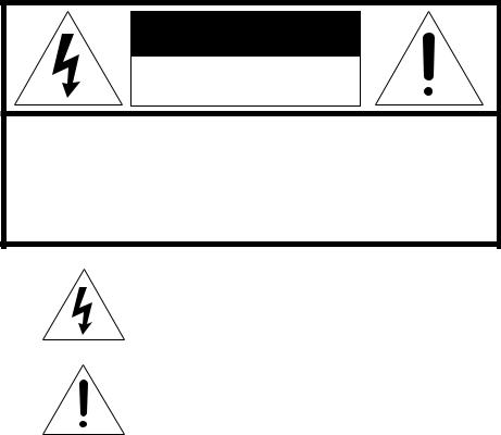
CAUTION |
RISK OF ELECTRIC SHOCK |
DO NOT OPEN |
CAUTION: TO REDUCE THE RISK OF ELECTRIC SHOCK, |
DO NOT REMOVE COVER (OR BACK) |
NO USER-SERVICEABLE PARTS INSIDE |
REFER SERVICING TO QUALIFIED SERVICE PERSONNEL |
The lightning flash with arrowhead symbol, within an equilateral triangle, is intended to alert the user to the presence of uninsulated “dangerous voltage” within the product’s enclosure that may be of suffi-cient magnitude to constitute a risk of electric shock to persons.
The exclamation point within an equilateral triangle is intended to alert the user to the presence of important operating and maintenance (servicing) instructions in the literature accompanying the appliance.
WARNING
TO REDUCE THE RISK OF FIRE OR ELECTRIC SHOCK,
DO NOT EXPOSE THIS APPLIANCE TO RAIN OR MOISTURE.
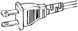
CAUTION: TO PREVENT ELECTRIC SHOCK, MATCH WIDE
BLADE OF PLUG TO WIDE SLOT, FULLY INSERT.
ATTENTION: POUR É VITER LES CHOCS É LECTRIQUES,
INTRODUIRE LA LAME LA PLUS LARGE DE LA FICHE DANS LA
BORNE CORRESPONDANTE DE LA PRISE ET POUSSER
JUSQU’AU FOND.
NOTE TO CATV SYSTEM INSTALLER:
This reminder is provided to call the CATV (Cable-TV) system installer’s attention to Article 820-40 of the NEC, that provides guidelines for proper grounding and, in particular, specified that the cable ground shall be connected to the grounding system of the building, as close to the point of cable entry as practical.
NOTE:
This equipment has been tested and found to comply with the limits for a Class B digital device, pursuant to Part 15 of the FCC Rules. These limits are designed to provide reasonable protection against harmful interference in a residential installation. This equipment generates, uses and can radiate radio frequency energy and, if not installed and used in accordance with the instructions, may cause harmful interference to radio communications. However, there is no guarantee that interference will not occur in a particular installation. If this equipment does cause harmful interference to radio or television reception, which can be determined by tuning the equipment off and on, the user is encouraged to try to
correct the interference by one or more of the following measures:
-Reorient or relocate the receiving antenna.
-Increase the separation between the equipment and receiver.
-Connect the equipment into an outlet on a circuit different from that to which the receiver is connected.
-Consult the dealer or an experienced radio/TV technician for help.
NOTE:
Changes or modifications may cause this unit to fail to comply with Part 15 of the FCC Rules and may void the user’s authority to operate the equipment.
31
IMPORTANT SAFETY
INSTRUCTIONS
READ BEFORE OPERATING EQUIPMENT
This product was designed and manufactured to meet strict quality and safety standards. There are, however, some installation and operation precautions which you should be particularly aware of.
1.Read Instructions - All the safety and operating instructions should be read before the appliance is operated.
2.Retain Instructions-The safety and operating instructions should be retained for future reference.
3.Heed Warnings-All warnings on the appliance and in the operating instructions should be adhered to.
4.Follow Instructions-All operating and use instructions should be followed.
5.Cleaning-Unplug this video product from the wall outlet before cleaning. Do not use liquid cleaners or aerosol cleaners. Use a damp cloth for cleaning.
6.Attachments-Do not use attachments not recommended by the video product manufacturer as they may cause hazards.
7.Water and Moisture-Do not use this video product near water-for example, near a bath tub, wash bowl, kitchen sink, or laundry tub, in a wet basement, or near a swimming pool, and the like.
8.Accessories-Do not place this video product on an unstable cart, stand, tripod, bracket, or table. The video product may fall, causing serious injury to a child or adult, and serious damage to the appliance. Use only with a cart, stand, tripod, bracket, or table recommended by the manufacturer, or sold with the video product. Any mounting of the appliance should follow the manufacturer’s instructions, and should use a mounting accessory recommended by the manufacturer.
9.Ventilation-Slots and openings in the cabinet are provided for ventilation and to ensure reliable operation of the video product and to protect it from overheating, and these openings must not be blocked or covered. The openings should never be blocked by placing the video product on a bed, sofa, rug, or other similar surface. This video product should never be placed near or over a radiator or heat register. This video product should not be placed in a built-in installation such as a bookcase or rack unless proper ventilation is provided or the manufacturer’s instructions have been adhered to.
10.Power Sources-This video product should be operated only from the type of power source indicated on the marking label. If you are not sure of the type of power supply to your home, consult your appliance dealer or local power company. For video products intended to operate from battery power, or other sources, refer to the operating instructions.
11.Grounding or Polarization-This video product is equipped with a polarized alternating-current line plug (a plug having one blade wider than the other). This plug will fit into the power outlet only one way. This is a safety feature. If you are unable to insert the plug fully into the outlet, try reversing the plug. If the plug should still fail to fit, contact your electrician to replace your obsolete outlet. Do not defeat the safety purpose of the polarized plug.
AC POLARIZED PLUG
12.Power-Cord Protection-Power-supply cords should be routed so that they are not likely to be walked on or pinched by items placed upon or against them, paying particular attention to cords at plugs, convenience receptacles, and the point where they exit from the appliance.
13.Protective Attachment Plug - The appliance is equipped with an attachment plug having overload protection. This is a safety feature. See Instruction Manual for replacement or resetting of protective device. If replacement of the plug is required, be sure the service technician has used a replacement plug specified by the manufacturer that has the same overload protection as the original plug.
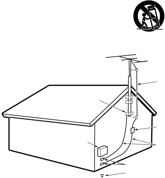
14.Outdoor Antenna Grounding-If an outside antenna or cable system is connected to the video product, be sure the antenna or cable system is grounded so as to provide some protection against voltage surges and built up static charges. Section 810 of the National Electrical Code, ANSI/NFPA No. 70-1984, provides information with respect to proper grounding of the mast and supporting structure, grounding of the lead-in wire to an antenna discharge unit, size of grounding conductors, location of antennadischarge unit, connection to grounding electrodes, and requirements for the grounding electrode. See Figure 1.
15.Lightning-For added protection for this video product receiver during a lightning storm, or when it is left un-attended and unused for long periods of time, unplug it from the wall outlet and disconnect the antenna or cable system. This will prevent damage to the video product due to lightning and power-line surges.
16.Power Lines-An outside antenna system should not be located in the vicinity of overhead power lines or other electric light or power circuits, or where it can fall into such power lines or circuits. When installing an outside antenna system, extreme care should be taken to keep from touching such power lines or circuits as contact with them might be fatal.
17.Overloading-Do not overload wall outlets and extension cords as this can result in a risk of fire or electric shock.
18.Object and Liquid Entry-Never push objects of any kind into this video product through openings as they may touch dangerous voltage points or short-out parts that could result in a fire or electric shock. Never spill liquid of any kind on the video product.
1
19.Servicing-Do not attempt to service this video product yourself as opening or removing covers may expose you to dangerous voltage or other hazards. Refer all servicing to qualified service personnel.
20.Damage Requiring Service-Unplug this video product from the wall outlet and refer servicing to qualified service personnel under the following conditions:
a.When the power-supply cord or plug is damaged.
b.If liquid has been spilled, or objects have fallen into the video product.
c.If the video product has been exposed to rain or water.
d.If the video product does not operate normally by following the operating instructions. Adjust only those controls that are covered by the operating instructions as an improper adjustment of other controls may result in damage and will often require extensive work by a qualified technician to restore the video product to its normal operation.
e.If the video product has been dropped or the cabinet has been damaged.
f.When the video product exhibits a distinct change in performance-this indicates a need for service.
21.Replacement Parts-When replacement parts are required, be sure the service technician has used replacement parts specified by the manufacturer or have the same characteristics as the original part. Unauthorized substitutions may result in fire, electric shock or other hazards.
22.Safety Check-Upon completion of any service or repairs to this video product, ask the service technician to perform safety checks to determine that the video product is in proper operating condition.
23.Carts and Stands-The appliance should be used only with a cart or stand that is recommended by the manufacturer.
24.An appliance and cart combination should be moved with care. Quick stops, excessive force, and uneven surfaces may cause the appliance and cart combination to overturn.
FIGURE 1
EXAMPLE OF ANTENNA GROUNDING ACCORDING TO
NATIONAL ELECTRICAL CODE INSTRUCTIONS
CONTAINED IN ARTICLE 810 - “RADIO AND TELEVISION EQUIPMENT”
ANTENNA
LEAD IN
WIRE
GROUND
CLAMP
|
ANTENNA |
|
|
DISCHARGE UNIT |
|
|
(NEC SECTION 810-20) |
|
ELECTRIC |
GROUNDING CONDUCTORS |
|
SERVICE |
||
(NEC SECTION 810-21) |
||
EQUIPMENT |
||
|
||
|
GROUND CLAMPS |
|
|
||
|
||
|
||
|
||
|
||
|
POWER SERVICE GROUNDING |
|
|
ELECTRODE SYSTEM |
|
|
(NEC ART 250, PART H) |
|
NEC - NATIONAL ELECTRICAL CODE |
||
|
|
|
This Class B digital apparatus meets all requirements of the Canadian |
Cet appareil numérique de la Classe B respecte toutes les exigences |
|
Interference - Cansing Equipment Regulations. |
du Règlement sur le matériel brouilleur du Canada. |
|
2
!5 |
@2@0 |
!9 |
!8 |
!7 |
!6 |
|
|
|
|
|
|
|
@1 |
|
|
|
|
|
|
@3 |
|
|
r y i !0 |
|
|
|
|
q |
w e |
t u o !1!2!3 |
!4 |
|
||
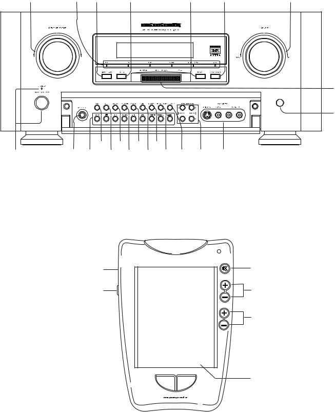
RC5000i
MUTE
v
CHANNEL
b
VOLUME
z x
c
n
3

ENGLISH
TABLE OF CONTENTS |
|
INTRODUCTION .............................................................................................................................................................. |
5 |
DESCRIPTION ................................................................................................................................................................. |
5 |
FEATURES ...................................................................................................................................................................... |
6 |
FRONT PANEL FEATURES ............................................................................................................................................ |
7 |
DISPLAY .......................................................................................................................................................................... |
9 |
REAR PANEL CONNECTIONS ..................................................................................................................................... |
10 |
REMOTE CONTROL UNIT RC5000i ............................................................................................................................. |
12 |
OPERATION OF REMOTE CONTROL UNIT ......................................................................................................................................................... |
14 |
SETUP ........................................................................................................................................................................... |
15 |
ON SCREEN DISPLAY MENU SYSTEM ............................................................................................................................................................... |
15 |
OSD MENU SYSTEM ............................................................................................................................................................................................ |
16 |
SPEAKERS SETUP AND LEVELS SETUP ........................................................................................................................................................... |
16 |
ON SCREEN DISPLAY INFOMATION ................................................................................................................................................................... |
19 |
BASIC OPERATION ...................................................................................................................................................... |
20 |
LISTENING TO THE TUNER .................................................................................................................................................................................. |
20 |
PLAYBACK OPERATION ....................................................................................................................................................................................... |
21 |
OTHER FUNCTIONS ..................................................................................................................................................... |
22 |
MULTI ROOM SELECTOR ..................................................................................................................................................................................... |
22 |
TV AUTO ON/OFF FUNCTION .............................................................................................................................................................................. |
22 |
SETTING THE SLEEP TIMER (ONLY REMOTE CONTROL UNIT) ....................................................................................................................... |
22 |
SURROUND MODES .................................................................................................................................................... |
23 |
TROUBLESHOOTING ................................................................................................................................................... |
26 |
TECHNICAL SPECIFICATIONS ................................................................................................................................... |
28 |
4
INTRODUCTION
Thank you for purchasing the Marantz SR-14EX THX/ DTS/Dolby Digital Surround receiver. This remarkable component has been engineered to provide you with many years of home theater enjoyment. Please take a few minutes to read this manual thoroughly before you connect and operate the SR-14EX. As there are a number of connection and configuration options, you are encouraged to discuss your own particular home theater setup with your Marantz A/ V specialist dealer.
DESCRIPTION
THX® is an exclusive set of standards and technologies established by the world-renowned film production company, Lucasfilm Ltd. THX resulted from George Lucas’ desire to reproduce the movie soundtrack as faithfully as possible both in the movie theater and in the home theater.
THX engineers developed patented technologies to accurately translate the sound from a movie theater environment into the home, correcting the tonal and spatial errors that occur.
When the THX mode of the SR-14EX is on, three distinct THX technologies are automatically added:
Re-Equalization-restores the correct tonal balance for watching a movie in a home environment.
These sounds are otherwise mixed to be brighter for a large movie theater. Re-EQ compensates for this and prevents the soundtracks from being overly bright and harsh when played in a home theater.
Timbre Matching-filters the information going to the surround speakers so they more closely match the tonal characteristics of the sound coming from the front speakers.
This ensures seamless panning between the front and surround speakers.
Adaptive Decorrelation-slightly changes one surround channel’s time and phase relationship with respect to the other surround channel. This expands the listening position and creates with only two surround speakers the same spacious surround experience as in a movie theater with multiple surround speakers.
The Marantz SR-14EX was required to pass a rigorous series of quality and performance tests, in addition to incorporating the technologies explained above, in order to be THX Ultra certified by Lucasfilm Ltd.
THX Ultra requirements cover every aspect of performance including pre-amplifier and power amplifier performance and operation, and hundreds of other parameters in both the digital and analog domain. Movies which have been encoded in Dolby Digital, DTS, Dolby Pro Logic, stereo and Mono will all benefit from the THX mode when being viewed.
The THX mode should only be activated when watching movies which were originally produced for a movie theater environment.
THX need not be activated for music, movies made especially for TV, or shows such as sports programming, talk shows, etc.
This is because they were originally mixed for a small room environment.
“Lucasfilm®” and “THX®” are registered trademarks of Lucasfilm Ltd.
THX Surround EX - Dolby Digital Surround EX is a joint development of Dolby Laboratories and the THX division of Lucasfilm Ltd.
In a movie theater, film soundtracks that have been encoded with Dolby Digital Surround EX technology are able to reproduce an extra channel which has been added during the mixing of the program.
This channel, called Surround Back, places sounds behind the listener in addition to the currently available front left, front center, front right, surround right, surround left and subwoofer channels.
This additional channel provides the opportunity for more detailed imaging behind the listener and brings more depth, spacious ambience and sound localization than ever before.
Movies that were created using the Dolby Digital Surround EX technology when released into the home consumer market may exhibit a Dolby Digital Surround EX logo on the packaging.
A list of movies created using this technology can be found on the Dolby web site at
http ://www.dolby.com.
“SURROUND EX ™” is a trademark of Dolby Laboratories. Used under authorization.
Dolby Digital lets you enjoy Digital TV, Digital Satellite as well as DVD, LD software in digital surround, which is the next step above Dolby Pro Logic.
In comparison with Dolby Pro Logic, Dolby Digital can provide separate left surround and right surround channels, for more precise localization of sounds and a more convincing, realistic ambience.
And, with Dolby Digital, all five main channels can be full ranged and a subwoofer can be added to each channel , if desired.
By providing up to 5.1channels of digital audio independently, Dolby Digital lets you enjoy better sound quality and more powerful presence than conventional Dolby Surround.
“Dolby”, “AC-3”, “Pro Logic” and the double-D symbol are trademarks of Dolby Laboratories.
DTS was introduced in 1994 to provide 5.1 channels of discrete digital audio into home theater systems.
DTS brings you premium quality discrete multi-channel digital sound to both movies and music.
DTS is a multi-channel sound system designed to create full range digital sound reproduction.
The no compromise DTS digital process sets the standard of quality for cinema sound by delivering an exact copy
of the studio master recordings to neighborhood and home theaters. Now, every moviegoer can hear the sound exactly as the moviemaker intended.
DTS can be enjoyed in the home for either movies or music on of DVD’s, LD’s, and CD’s.
“DTS” and “DTS Digital Surround” are trademarks of Digital Theater Systems, Inc.
ENGLISH
5
ENGLISH
®
HDCD® (High Definition Compatible Digital ®) is a patented process for delivering on Compact Disc the full richness and details of the original microphone feed.
HDCD encoded CDs sound better because they are encoded with 20bits of real musical information as compared to 16-bits for all other CDs.
HDCD overcomes the limitation of the 16-bit CD format by using a sophisticated system to encode the additional four bits onto the CD while remaining completely compatible with the CD format.
When listening to HDCD recordings, you hear more dynamic range, a focused 3-D sound stage, and extremely natural vocal and musical timbre. With HDCD, you get the body, depth and emotion of the original performance not a flat, digital imitation.
 ®, HDCD®, High Definition Compatible Digital ® and Pacific Microsonics™ are either registered trademarks or trademarks of Pacific Microsonics, Inc. in the United States and/or other countries. HDCD system manufactured under license from Pacific Microsonics, Inc. This product is covered by one or more of the following: In the USA: 5,479,168, 5,638,074, 5,640,161, 5,808,574, 5,838,274, 5,854,600, 5,864,311, 5,872,531, and in Australia: 669114. Other patents pending.
FEATURES
•THX SURROUND EX decoding to reproduce an extra channel which has been added during the mixing of the program.
•Dolby Digital and DTS surround sound decoding, plus THX Cinema processing, Dolby Pro Logic decoding and a variety of additional surround modes.
•HDCD decoding capability to deliver the full sonic benefits of HDCD-encoded CDs from a standard non-HDCD CD player when connected to the SR-14EX via the player ’s digital output.
•96 kHz/ 24 bit decoding for highest possible fidelity and bandwidth, and high-resolution playback of 96 kHz/ 24 bit PCM audio sources.
•Poly Silicon high resolution 8 ch Volume control
•Selectable main input terminals (L/R or Surr.Back L/R)
•140 watts to each of the five main channels; the power amp section features an advanced, premium highstorage power supply capacitors, and fully discrete output stages housed in cast aluminum heat sinks .
•High Definition Amplifier Module (HDAM) discrete pre-amp output stages.
•7.1 channel pre-amp outputs for connection to external components such as a subwoofer and external power amplifiers.
•Six-channel direct inputs accommodate future surround sound formats or an external digital decoder.
•Six Digital inputs, for connection to other sources, such as DVD, DSS, CD or LD.
•Two Digital outputs for connection to CD-R or MD.
•High-quality AM/FM tuner with 50 station presets.
•Source Direct switch bypasses, tone controls and bass management for purest audio quality.
•Three sets of Y/Pr/Pb component video inputs and component video outputs provide unsurpassed video quality and switching flexibility from component video sources.
•OnScreenDisplay with both Composite and “S” video.
•Front panel A/V inputs, with S-video .
•Easy to use on-screen menu.
•Multi-room capability offers independent control of a second room audio and video system.
•Supplied with RC5000i programmable learning remote control.
6
 Loading...