


Manitowoc Ice UD0140A, UD0140W, UD0140AE, UD0140WE, UY0140A Manuel de service
...
Undercounter Ice Machines
Technician’s Handbook
This manual is updated as new information and models are released. Visit our website for the latest manual. www.manitowocice.com
Part Number STH042 7/15

Safety Notices
As you work on Manitowoc equipment, be sure to pay close attention to the safety notices in this handbook. Disregarding the notices may lead to serious injury and/ or damage to the equipment.
Throughout this handbook, you will see the following types of safety notices:
Warning
Text in a Warning box alerts you to a potential personal injury situation. Be sure to read the Warning statement before proceeding, and work carefully.
Caution
Text in a Caution box alerts you to a situation in which you could damage the equipment. Be sure to read the Caution statement before proceeding, and work carefully.

Procedural Notices
As you work on Manitowoc equipment, be sure to read the procedural notices in this handbook. These notices supply helpful information which may assist you as you work.
Throughout this handbook, you will see the following types of procedural notices:
Important
Text in an Important box provides you with information that may help you perform a procedure more efficiently. Disregarding this information will not cause damage or injury, but it may slow you down as you work.
NOTE: Text set off as a Note provides you with simple, but useful, extra information about the procedure you are performing.

Read These Before Proceeding:
Caution
Proper installation, care and maintenance are essential for maximum performance and troublefree operation of your Manitowoc equipment. If you encounter problems not covered by this manual, do not proceed, contact Manitowoc Foodservice. We will be happy to provide assistance.
Caution
Proper installation, care and maintenance are essential for maximum performance and trouble-free operation of your equipment. Visit our website www. manitowocfsg.com for manual updates, translations, or contact information for service agents in your area.
Important
Routine adjustments and maintenance procedures outlined in this handbook are not covered by the warranty.
Warning
Read this manual thoroughly before operating, installing or performing maintenance on the equipment. Failure to follow instructions in this manual can cause property damage, injury or death.

Warning
Do not use electrical appliances or accessories other than those supplied by Manitowoc for your ice machine model.
Warning
Two or more people or a lifting device are required to lift this appliance.
Warning
This equipment contains high voltage electricity and refrigerant charge. Installation and repairs are to be performed by properly trained technicians aware of the dangers of dealing with high voltage electricity and refrigerant under pressure. The technician must also be certified in proper refrigerant handling and servicing procedures. All lockout and tag out procedures must be followed when working on this equipment.
Warning
Do not damage the refrigeration circuit when installing, maintaining or servicing the unit.
Important
This product is hermetically sealed and contains fluorinated greenhouse gas R404A

Warning
Do not operate equipment that has been misused, abused, neglected, damaged, or altered/modified from that of original manufactured specifications. This appliance is not intended for use by persons (including children) with reduced physical, sensory or mental capabilities, or lack of experience and knowledge, unless they have been given supervision concerning use of the appliance by a person responsible for their safety. Do not allow children to play with this appliance.
Warning
All covers and access panels must be in place and properly secured, before operating this equipment.
Warning
Do not obstruct machine vents or openings.
Warning
Do not store gasoline or other flammable vapors or liquids in the vicinity of this or any other appliance.
Warning
Do not clean with water jet.
Warning
It is the responsibility of the equipment owner to perform a Personal Protective Equipment Hazard Assessment to ensure adequate protection during maintenance procedures.
Warning
Two or more people are required to move this equipment to prevent tipping.

Warning
When using electric appliances, basic precautions must always be followed, including the following:
a.Read all the instructions before using the appliance.
b.To reduce the risk of injury, close supervision is necessary when an appliance is used near children.
c.Do not contact moving parts.
d.Only use attachments recommended or sold by the manufacturer.
e.Do not use outdoors.
f.For a cord-connected appliance, the following must be included:
•Do not unplug by pulling on cord. To unplug, grasp the plug, not the cord.
•Unplug from outlet when not in use and before servicing or cleaning.
•Do not operate any appliance with a damaged cord or plug, or after the
appliance malfunctions or is dropped or damaged in any manner. Contact the nearest authorized service facility for examination, repair, or electrical or mechanical adjustment.
g.Follow applicable lock out tag out procedures before working on equipment.
h.Connect to a properly grounded outlet only.
We reserve the right to make product improvements at any time. Specifications and design are subject to change without notice.

Table of Contents
General Information
Model Numbers. . . . . . . . . . . . . . . . . . . . . . . . . . . . . . . 13
How to Read a Model Number . . . . . . . . . . . . . . . . 14 Ice Machine Warranty Information. . . . . . . . . . . . 15 Commercial Warranty Coverage. . . . . . . . . . . . 15 Residential Warranty Coverage. . . . . . . . . . . . . 17 How to Obtain Warranty Service . . . . . . . . . . . 19
Installation
Location of Ice Machine. . . . . . . . . . . . . . . . . . . . . . . 21
Ice Machine Clearance Requirements . . . . . . . . . 22
Ice Machine Heat of Rejection . . . . . . . . . . . . . . . . 22
Leveling the Ice Machine. . . . . . . . . . . . . . . . . . . . . . 23
Electrical Requirements. . . . . . . . . . . . . . . . . . . . . . . 24
Electrical Specifications. . . . . . . . . . . . . . . . . . . . . . . 25
Water Service/Drains . . . . . . . . . . . . . . . . . . . . . . . . . 27
Water Supply. . . . . . . . . . . . . . . . . . . . . . . . . . . . . . 27
Water Inlet Lines . . . . . . . . . . . . . . . . . . . . . . . . . . 27
Drain Connections . . . . . . . . . . . . . . . . . . . . . . . . 28
Cooling Tower Applications. . . . . . . . . . . . . . . . 28
Water Supply and Drain Line Sizing/
Connections . . . . . . . . . . . . . . . . . . . . . . . . . . . . . . 29
Maintenance
Interior Cleaning and Sanitizing . . . . . . . . . . . . . . 31 General . . . . . . . . . . . . . . . . . . . . . . . . . . . . . . . . . . . 31 Cleaning and Sanitizing Procedure. . . . . . . . . 31 Touch Pad Operation . . . . . . . . . . . . . . . . . . . . . . 32 Remove Parts for Cleaning. . . . . . . . . . . . . . . . . 36
Preventative Maintenance Cleaning . . . . . . . . . . 41
Ice Machine Inspection . . . . . . . . . . . . . . . . . . . . . . . 42 Cleaning the Condenser . . . . . . . . . . . . . . . . . . . . . . 43
Removal from Service/Winterization . . . . . . . . . 44
Bin Removal . . . . . . . . . . . . . . . . . . . . . . . . . . . . . . . . . . 45
Part Number STH042 7/15 |
9 |
Operation
Touch Pad Features . . . . . . . . . . . . . . . . . . . . . . . . . . . 47
On/Off . . . . . . . . . . . . . . . . . . . . . . . . . . . . . . . . . . . . 47
Delay . . . . . . . . . . . . . . . . . . . . . . . . . . . . . . . . . . . . . 48
Clean . . . . . . . . . . . . . . . . . . . . . . . . . . . . . . . . . . . . . 48
Bin Full. . . . . . . . . . . . . . . . . . . . . . . . . . . . . . . . . . . . 49
Service. . . . . . . . . . . . . . . . . . . . . . . . . . . . . . . . . . . . 49
Ice Making Sequence of Operation . . . . . . . . . . . 50
Control Board Timers . . . . . . . . . . . . . . . . . . . . . . 52
Safety Limits . . . . . . . . . . . . . . . . . . . . . . . . . . . . . . 53
Energized Parts Chart. . . . . . . . . . . . . . . . . . . . . . 55
Operational Checks . . . . . . . . . . . . . . . . . . . . . . . . . . . 57
Ice Thickness Check . . . . . . . . . . . . . . . . . . . . . . . 57
Ice Thickness Adjustment. . . . . . . . . . . . . . . . . . 57
Troubleshooting
Control Board Test Mode. . . . . . . . . . . . . . . . . . . . . . 59 Operating Ice Machine with Bin and Touch Pad Removed . . . . . . . . . . . . . . . . . . . . . . . . . . . . . . . . . 59
Diagnosing an Ice Machine that Will Not Run . 60
Ice Machine Does Not Cycle Into Harvest when Water Loses Contact with the Harvest Float Switch. . . . . . . . . . . . . . . . . . . . . . . . . . . . . . . . . . . . . . . . . 61
Ice Machine Cycles Into Harvest Before Water Loses Contact with the Harvest Float Switch. . 63
Ice Production Check . . . . . . . . . . . . . . . . . . . . . . . . . 65
Installation/Visual Inspection Checklist . . . . . . 67
Water System Checklist . . . . . . . . . . . . . . . . . . . . . . . 68 Ice Formation Pattern. . . . . . . . . . . . . . . . . . . . . . . . . 69 Safety Limit Feature . . . . . . . . . . . . . . . . . . . . . . . . . . 71
Analyzing Discharge Pressure . . . . . . . . . . . . . . . . 78 Analyzing Suction Pressure . . . . . . . . . . . . . . . . . . 80
Harvest Valve . . . . . . . . . . . . . . . . . . . . . . . . . . . . . . . . . 84
Comparing Evaporator Inlet/Outlet Temperatures . . . . . . . . . . . . . . . . . . . . . . . . . . . . . . . . . 88
Discharge Line Temperature Analysis. . . . . . . . . 89 Refrigeration Component Diagnostics. . . . . . . . 91 Procedure. . . . . . . . . . . . . . . . . . . . . . . . . . . . . . . . . 92 Final Analysis. . . . . . . . . . . . . . . . . . . . . . . . . . . . . . 93 Refrigeration Component Diagnostic Chart 94
10 |
Part Number STH042 7/15 |
Component Check Procedures
Main Fuse . . . . . . . . . . . . . . . . . . . . . . . . . . . . . . . . . . . . . 97 Bin Switch. . . . . . . . . . . . . . . . . . . . . . . . . . . . . . . . . . . . . 98 Touch Pad . . . . . . . . . . . . . . . . . . . . . . . . . . . . . . . . . . . . 100 Float Switch. . . . . . . . . . . . . . . . . . . . . . . . . . . . . . . . . . 102
Compressor Electrical Diagnostics. . . . . . . . . . . 104
Fan Cycle Control . . . . . . . . . . . . . . . . . . . . . . . . . . . . 106
High Pressure Cutout (HPCO) Control. . . . . . . . 107
Filter-Driers . . . . . . . . . . . . . . . . . . . . . . . . . . . . . . . . . . 108
Refrigerant Recovery/Evacuation. . . . . . . . . . . . 109 Definitions . . . . . . . . . . . . . . . . . . . . . . . . . . . . . . . 109 Refrigerant Re-use Policy . . . . . . . . . . . . . . . . . 110 Recovery and Recharging Procedures . . . . 112
System Contamination Cleanup . . . . . . . . . . . . . 115 Determining Severity of Contamination . . . 115 Mild System Contamination Cleanup Procedure. . . . . . . . . . . . . . . . . . . . . . . . . . . . . . . . 117 Severe System Contamination Cleanup Procedure. . . . . . . . . . . . . . . . . . . . . . . . . . . . . . . . 118 Replacing Pressure Controls without Removing Refrigerant Charge. . . . . . . . . . . . . 119
Total System Refrigerant Charge. . . . . . . . . . . . . 121
Part Number STH042 7/15 |
11 |
Charts
Cycle Times, 24 Hr. Ice Production and
Refrigerant Pressure Charts. . . . . . . . . . . . . . . . . . 123
U0140 Self-contained Air-cooled. . . . . . . . . . 124
U0140 Self-contained Water-cooled. . . . . . . 125
U0190 Self-contained Air-cooled. . . . . . . . . . 126
U0240 Self-contained Air-cooled. . . . . . . . . . 127
U0240 Self-contained Water-cooled. . . . . . . 128
U0310 Self-contained Air-cooled. . . . . . . . . . 129
U0310 Self-contained Water-cooled. . . . . . . 130
Diagrams
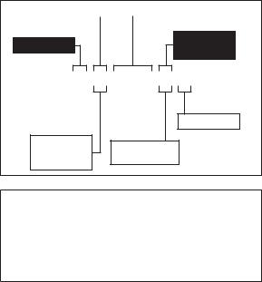
Wiring Diagrams . . . . . . . . . . . . . . . . . . . . . . . . . . . . . 131 Wiring Diagrams
U140/U190/U240 wiring diagram . . . . . . . . . 132 Electronic Control Board. . . . . . . . . . . . . . . . . . 134 Tubing Schematic - U0140 . . . . . . . . . . . . . . . . . . . 135
Tubing Schematic - U0190/U0240/U0310. . . . 136
12 |
Part Number STH042 7/15 |

General Information
Model Numbers
This manual covers the following models:
Self-contained |
Self-contained |
Air-cooled |
Water-cooled |
UD0140A |
UD0140W |
UD0140AE |
UD0140WE |
UY0140A |
UY0140W |
UY0140AE |
UY0140WE |
UR0140A |
– |
UR0140AE |
– |
UD0190A |
– |
UD0190AE |
– |
UY0190A |
– |
UY0190AE |
– |
UR0190A |
– |
UR0190AE |
– |
UD0240A |
UD0240W |
UD0240AE |
UD0240WE |
UY0240A |
UY0240W |
UY0240AE |
UY0240WE |
UR0240A |
– |
UR0240AE |
– |
UD0310A |
UD0310W |
UD0310AE |
UD0310WE |
UY0310A |
UY0310W |
UY0310AE |
UY0310WE |
UR0310A |
– |
UR0310AE |
– |
Part Number STH042 7/15 |
13 |
How to Read a Model Number
Cube Size |
|
|
|
Capacity |
|
|
|
||
|
|
|
|
|
Series
Condenser
Type
U D 0140 A E
E - WRAS 50Hz
R - Regular
D - Dice
A - Air-cooled
Y - Half-dice
W - Water-cooled
Warning
An ice machine contains high voltage electricity and refrigerant charge. Repairs are to be performed by properly trained refrigeration technicians aware of the dangers of dealing with high voltage electricity and refrigerant under pressure.
14 |
Part Number STH042 7/15 |

Ice Machine Warranty Information
Owner Warranty Registration Card
General
Warranty coverage begins the day the ice machine is installed.
Important
Complete and mail the OWNER WARRANTY REGISTRATION CARD as soon as possible to validate the installation date.
If the OWNER WARRANTY REGISTRATION CARD is not returned, Manitowoc will use the date of sale to the Manitowoc Distributor as the first day of warranty coverage for your new ice machine.
COMMERCIAL WARRANTY COVERAGE
General
The following Warranty outline is provided for your convenience. For a detailed explanation, read the warranty bond shipped with each product.
Contact your local Manitowoc representative or Manitowoc Ice, if you need further warranty information.
Parts
1.Manitowoc warrants the ice machine against defects in materials and workmanship, under normal use and service for three (3) years from the date of original installation.
2.The evaporator and compressor are covered by an additional two (2) year (five years total) warranty beginning on the date of the original installation.
Labor
1.Labor required to repair or replace defective components is covered for three (3) years from the date of original installation.
2.The evaporator is covered by an additional two- (2) year (five years total) labor warranty beginning on the date of the original installation.
Part Number STH042 7/15 |
15 |
Exclusions
The following items are not included in the ice machine’s warranty coverage:
1.Normal maintenance, adjustments and cleaning as outlined in this manual.
2.Repairs due to unauthorized modifications to the ice machine or use of non-standard parts without prior written approval from Manitowoc Ice.
3.Damage caused by improper installation of the ice machine, electrical supply, water supply or drainage, or damage caused by floods, storms, or other acts of God.
4.Premium labor rates due to holidays, overtime, etc.; travel time; flat rate service call charges; mileage and miscellaneous tools and material charges not listed on the payment schedule. Additional labor charges resulting from the inaccessibility of equipment are also excluded.
5.Parts or assemblies subjected to misuse, abuse, neglect or accidents.
6.Damage or problems caused by installation, cleaning and/or maintenance procedures inconsistent with the technical instructions provided in this manual.
7.This warranty is intended exclusively for commercial application. No warranty is extended for personal, family, or household purposes.
Authorized Warranty Service
To comply with the provisions of the warranty, a refrigeration service company qualified and authorized by your Manitowoc distributor, or a Factory Authorized Servicer must perform the warranty repair.
Service Calls
Normal maintenance, adjustments and cleaning as outlined in this manual are not covered by the warranty.
16 |
Part Number STH042 7/15 |
RESIDENTIAL WARRANTY COVERAGE
What Does this Limited Warranty Cover?
Subject to the exclusions and limitations below, Manitowoc Ice (“Manitowoc”) warrants to the original consumer that any new ice machine manufactured by Manitowoc (the “Product”) shall be free of defects in material or workmanship for the warranty period outlined below under normal use and maintenance, and upon proper installation and start-up in accordance with the instruction manual supplied with the Product.
How Long Does this Limited Warranty Last?
Product Covered |
Warranty Period |
Ice Machine |
Twelve (12) months |
|
from the sale date |
Who Is Covered by this Limited Warranty?
This limited warranty only applies to the original consumer of the Product and is not transferable.
What Are MANITOWOC ICE’S Obligations Under this Limited Warranty?
If a defect arises and Manitowoc receives a valid warranty claim prior to the expiration of the warranty period, Manitowoc shall, at its option: (1) repair the Product at Manitowoc’s cost, including standard straight time labor charges, (2) replace the Product with one that is new or at least as functionally equivalent as the original, or (3) refund the purchase price for the Product. Replacement parts are warranted for 90 days or the balance of the original warranty period, whichever is longer. The foregoing constitutes Manitowoc’s sole obligation and the consumer’s exclusive remedy for any breach of this limited warranty. Manitowoc’s liability under this limited warranty is limited to the purchase price of Product. Additional expenses including, without limitation, service travel time, overtime or premium labor charges, accessing or removing the Product, or shipping are the responsibility of the consumer.
Part Number STH042 7/15 |
17 |
What Is Not Covered?
This limited warranty does cover, and you are solely responsible for the costs of: (1) periodic or routine maintenance, (2) repair or replacement of the Product or parts due to normal wear and tear, (3) defects or damage to the Product or parts resulting from misuse, abuse, neglect, or accidents, (4) defects or damage to the
Product or parts resulting from improper or unauthorized alterations, modifications, or changes; and (5) defects or damage to any Product that has not been installed and/ or maintained in accordance with the instruction manual or technical instructions provided by Manitowoc. To the extent that warranty exclusions are not permitted under some state laws, these exclusions may not apply to you.
EXCEPT AS STATED IN THE FOLLOWING SENTENCE, THIS LIMITED WARRANTY IS THE SOLE AND EXCLUSIVE WARRANTY OF MANITOWOC WITH REGARD TO THE PRODUCT. ALL IMPLIED WARRANTIES ARE STRICTLY LIMITED TO THE DURATION OF THE LIMITED WARRANTY APPLICABLE TO THE PRODUCTS AS STATED ABOVE, INCLUDING BUT NOT LIMITED TO, ANY WARRANTY OF MERCHANTABILITY OR OF FITNESS FOR A PARTICULAR PURPOSE. Some states do not allow limitations on how long an implied warranty lasts, so the above limitation may not apply to you.
IN NO EVENT SHALL MANITOWOC OR ANY OF ITS AFFILIATES BE LIABLE TO THE CONSUMER OR ANY OTHER PERSON FOR ANY INCIDENTAL, CONSEQUENTIAL OR SPECIAL DAMAGES OF ANY
KIND (INCLUDING, WITHOUT LIMITATION, LOSS OF PROFITS, REVENUE OR BUSINESS) ARISING FROM OR IN ANY MANNER CONNECTED WITH THE PRODUCT, ANY BREACH OF THIS LIMITED WARRANTY, OR ANY OTHER CAUSE WHATSOEVER, WHETHER BASED ON CONTRACT, TORT OR ANY OTHER THEORY OF LIABILITY. Some states do not allow the exclusion or limitation of incidental
or consequential damages, so the above limitation or exclusion may not apply to you.
18 |
Part Number STH042 7/15 |
How State Law Applies
This limited warranty gives you specific legal rights, and you may also have rights that vary from state to state or from one jurisdiction to another.
Registration Card
To secure prompt and continuing warranty service, this warranty registration card must be completed and sent to Manitowoc within thirty (30) days from the sale date. Complete the following registration card and send it to Manitowoc at the address shown above. Retain a copy for your records.
HOW TO OBTAIN WARRANTY SERVICE
To obtain warranty service or information regarding your Product, please contact us at:
MANITOWOC ICE
2110 S. 26th St.,
P.O. Box 1720
Manitowoc, WI 54221-1720
Telephone: 920-682-0161 Fax: 920-683-7585
www.manitowocice.com
Part Number STH042 7/15 |
19 |
THIS PAGE INTENTIONALLY LEFT BLANK
20 |
Part Number STH042 7/15 |
Installation
Location of Ice Machine
The location selected for the ice machine must meet the following criteria. If any of these criteria are not met, select another location.
•The location must be indoors.
•The location must be free of airborne and other contaminants.
•Air temperature: Must be at least 40°F (4°C) but must not exceed 110°F (43.4°C).
•The location must not be near heat-generating equipment or in direct sunlight.
•The location must be capable of supporting the weight of the ice machine and a full bin of ice.
•The location must allow enough clearance for water, drain, and electrical connections in the rear of the ice machine.
•The location must not obstruct airflow through or around the ice machine (condenser airflow is in and out the front). Refer to the chart below for clearance requirements.
•The ice machine must be protected if it will be subjected to temperatures below 32°F (0°C). Failure caused by exposure to freezing temperatures is not covered by the warranty.
Part Number STH042 7/15 |
21 |
Ice Machine Clearance Requirements
|
Self-contained |
Self-contained |
|
Air-cooled |
Water-cooled |
Top/Sides |
5" (127 mm)* |
5" (127 mm)* |
Back |
5" (127 mm)* |
5" (127 mm)* |
*The ice machine may be built into a cabinet.
There is no minimum clearance requirement for the top or left and right sides of the ice machine. The listed values are recommended for efficient operation and servicing only.
Ice Machine Heat of Rejection
Series |
Heat of Rejection* |
|
|
Ice Machine |
Air Conditioning** |
|
Peak |
U140 |
2400 |
|
2900 |
U190 |
2200 |
|
2600 |
U240 |
2400 |
|
3400 |
U310 |
3800 |
|
6000 |
* B.T.U./Hour
**Because the heat of rejection varies during the ice making cycle, the figure shown is an average.
Ice machines, like other refrigeration equipment, reject heat through the condenser. It is helpful to know the amount of heat rejected by the ice machine when sizing air conditioning equipment where self-contained aircooled ice machines are installed.
22 |
Part Number STH042 7/15 |
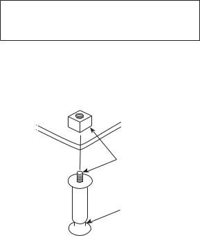
Leveling the Ice Machine
1.Screw the leveling legs onto the bottom of the ice machine.
2.Screw the foot of each leg in as far as possible.
Caution
The legs must be screwed in tightly to prevent them from bending.
3.Move the ice machine into its final position.
4.Level the ice machine to ensure that the siphon system functions correctly. Use a level on top of the ice machine. Turn each foot as necessary to level the ice machine from front to back and side to side.
THREAD
LEVELING LEG
INTO BASE OF
CABINET
THREAD “FOOT”
IN AS FAR AS
POSSIBLE
SV1606
Leg Installation
Part Number STH042 7/15 |
23 |
Electrical Requirements
Voltage
The maximum allowable voltage variation is ±10% of the rated voltage on the ice machine model/serial number plate at start-up (when the electrical load is highest).
Fuse/Circuit Breaker
A separate fuse/circuit breaker must be provided for each ice machine.
Total Circuit Ampacity
The total circuit ampacity is used to help select the wire size of the electrical supply.
The wire size (or gauge) is also dependent upon location, materials used, length of run, etc., so it must be determined by a qualified electrician.
24 |
Part Number STH042 7/15 |
Electrical Specifications
Air-cooled Ice Machine
|
Voltage |
Max. Fuse/ |
|
|
Ice Machine |
Circuit |
Total Amps |
||
Phase Cycle |
||||
|
Breaker |
|
||
|
|
|
||
|
115/1/60 |
15 |
5.0 |
|
U140 |
208-230/1/60 |
15 |
2.5 |
|
|
230/1/50 |
15 |
2.5 |
|
|
115/1/60 |
15 |
6.0 |
|
U190 |
208-230/1/60 |
15 |
2.5 |
|
|
230/1/50 |
15 |
2.5 |
|
|
115/1/60 |
15 |
7.0 |
|
U240 |
208-230/1/60 |
15 |
4.0 |
|
|
230/1/50 |
15 |
4.0 |
|
|
115/1/60 |
15 |
10.0 |
|
U310 |
208-230/1/60 |
15 |
4.5 |
|
|
230/1/50 |
15 |
4.5 |
Part Number STH042 7/15 |
25 |
Water-cooled Ice Machine
|
Voltage |
Max. Fuse/ |
|
|
Ice Machine |
Circuit |
Total Amps |
||
Phase Cycle |
||||
|
Breaker |
|
||
|
|
|
||
|
115/1/60 |
15 |
5.0 |
|
U140 |
208-230/1/60 |
15 |
2.5 |
|
|
230/1/50 |
15 |
2.5 |
|
|
115/1/60 |
15 |
7.0 |
|
U240 |
208-230/1/60 |
15 |
4.0 |
|
|
230/1/50 |
15 |
4.0 |
|
|
115/1/60 |
15 |
10.0 |
|
U310 |
208-230/1/60 |
15 |
4.5 |
|
|
230/1/50 |
15 |
4.5 |
Warning
All wiring must conform to local, state and national codes.
Warning
The ice machine must be grounded in accordance with national and local electrical code.
26 |
Part Number STH042 7/15 |
Water Service/Drains
WATER SUPPLY
Local water conditions may require treatment of the water to inhibit scale formation, filter sediment, and remove chlorine odor and taste.
Important
If you are installing a Manitowoc water filter system, refer to the Installation Instructions supplied with the filter system for ice making water inlet connections.
Warning
For ice making, connect to a potable water supply only.
WATER INLET LINES
Follow these guidelines to install water inlet lines:
•Do not connect the ice machine to a hot water supply. Be sure all hot water restrictors installed for other equipment are working. (Check valves on sink faucets, dishwashers, etc.)
•If water pressure exceeds the maximum recommended pressure, 80 psig (5.5 bar) obtain a water pressure regulator from your Manitowoc distributor.
•Install a water shut-off valve for ice making potable water.
•Insulate water inlet lines to prevent condensation.
Part Number STH042 7/15 |
27 |
DRAIN CONNECTIONS
Follow these guidelines when installing drain lines to prevent drain water from flowing back into the ice machine and storage bin:
•Drain lines must have a 1.5-inch drop per 5 feet of run (2.5 cm per meter), and must not create traps.
•The floor drain must be large enough to accommodate drainage from all drains.
•Install a tee to vent the ice machine drain to the atmosphere.
•Insulate drain lines to prevent condensation.
COOLING TOWER APPLICATIONS
Water Cooled Models Only
A water-cooling tower installation does not require modification of the ice machine. The water regulator valve for the condenser continues to control the refrigeration discharge pressure.
It is necessary to know the amount of heat rejected, and the pressure drop through the condenser and water valves (inlet to outlet) when using a cooling tower on an ice machine.
•Water entering the condenser must not exceed 90°F (32.2°C).
•Water flow through the condenser must not exceed 5 gallons (19 liters) per minute.
•Allow for a pressure drop of 7 psig (.48 bar) between the condenser water inlet and the outlet of the ice machine.
•Water exiting the condenser must not exceed 110°F (43.3°C).
Caution
Plumbing must conform to state and local codes.
28 |
Part Number STH042 7/15 |
Part |
|
Water |
Water |
Ice Machine |
Tubing Size Up |
|
Location |
to Ice Machine |
|||||
Number |
Temperature |
Pressure |
Fitting |
|||
|
Fitting |
|||||
|
|
|||||
|
|
|
|
|
||
|
Ice Making |
40°F (4°C) min. |
20 psi (138 kPa) min. |
3/8” Female |
3/8" (9.5 mm) min. |
|
STH042 |
Water Inlet |
90°F (32°C) max. |
80 psi (550 kPa) max. |
Pipe Thread |
inside diameter |
|
Water Inlet |
90°F (32°C) max |
150 psi (10.3 bar) max. |
Pipe Thread |
inside diameter |
||
|
Condenser |
40°F (4°C) min. |
20 psi (1.38 bar) min. |
3/8” Female |
3/8" (9.5 mm) min. |
|
7/15 |
|
|
|
|
|
|
Condenser |
— |
— |
3/8” Female |
3/8" (9.5 mm) min. |
||
|
||||||
|
Water Drain |
Pipe Thread |
inside diameter |
|||
|
|
|
SIZING/ LINE DRAIN AND SUPPLY WATER CONNECTIONS
29
THIS PAGE INTENTIONALLY LEFT BLANK
30 |
Part Number STH042 7/15 |
 Loading...