


 Loading...
S Model & Ice Beverage
QuietQube® Ice Machines
with CVD® Technology
Installation, Use & Care Manual
This manual is updated as new information and models are released. Visit our website for the latest manual. www.manitowocfsg.com
America’s #1 Selling Ice Machine
Part Number 000002477 3/08
Safety Notices
As you work on Manitowoc equipment, be sure to pay close attention to the safety notices in this manual. Disregarding the notices may lead to serious injury and/ or damage to the equipment.
Throughout this manual, you will see the following types of safety notices:
! Warning
Text in a Warning box alerts you to a potential personal injury situation. Be sure to read the Warning statement before proceeding, and work carefully.
! Caution
Text in a Caution box alerts you to a situation in which you could damage the equipment. Be sure to read the Caution statement before proceeding, and work carefully.
Procedural Notices
As you work on Manitowoc equipment, be sure to read the procedural notices in this manual. These notices supply helpful information which may assist you as you work.
Throughout this manual, you will see the following types of procedural notices:
Important
Text in an Important box provides you with information that may help you perform a procedure more efficiently. Disregarding this information will not cause damage or injury, but it may slow you down as you work.
NOTE: Text set off as a Note provides you with simple, but useful, extra information about the procedure you are performing.
Read These Before Proceeding:
! Caution
Proper installation, care and maintenance are essential for maximum performance and troublefree operation of your Manitowoc equipment. Read and understand this manual. It contains valuable care and maintenance information. If you encounter problems not covered by this manual, do not proceed, contact Manitowoc Foodservice Group. We will be happy to provide assistance.
Important
Routine adjustments and maintenance procedures outlined in this manual are not covered by the warranty.
! Warning
PERSONAL INJURY POTENTIAL
Do not operate equipment that has been misused, abused, neglected, damaged, or altered/modified from that of original manufactured specifications.
NOTE: SAVE THESE INSTRUCTIONS.
We reserve the right to make product improvements at any time. Specifications and design are subject to change without notice.

Table of Contents
Section 1
General Information
Model Numbers . . . . . . . . . . . . . . . . . . . . . . . . . . . . . . . . . . . . . . . . . . . . . . . . . |
1-1 |
How to Read a Model Number . . . . . . . . . . . . . . . . . . . . . . . . . . . . . . . . . . . . . |
1-1 |
Remote Condensing Unit . . . . . . . . . . . . . . . . . . . . . . . . . . . . . . . . . . . . . . . . . |
1-1 |
Ice Cube Sizes . . . . . . . . . . . . . . . . . . . . . . . . . . . . . . . . . . . . . . . . . . . . . . . . . . |
1-1 |
Accessories . . . . . . . . . . . . . . . . . . . . . . . . . . . . . . . . . . . . . . . . . . . . . . . . . . . . |
1-2 |
Ice Bagger . . . . . . . . . . . . . . . . . . . . . . . . . . . . . . . . . . . . . . . . . . . . . . . . . . |
1-2 |
Ice Deflector . . . . . . . . . . . . . . . . . . . . . . . . . . . . . . . . . . . . . . . . . . . . . . . . |
1-2 |
Electronic Bin Thermostat Kit - K00364 . . . . . . . . . . . . . . . . . . . . . . . . . . . |
1-2 |
CVD1486 Water Cooled Condensing Unit . . . . . . . . . . . . . . . . . . . . . . . . . |
1-2 |
Stacking Two Ice Machines on a Single Dispenser . . . . . . . . . . . . . . . . . . |
1-2 |
Arctic Pure Water Filter System . . . . . . . . . . . . . . . . . . . . . . . . . . . . . . . . . |
1-2 |
Manitowoc Cleaner and Sanitizer . . . . . . . . . . . . . . . . . . . . . . . . . . . . . . . . |
1-2 |
Guardian Sachet Packets . . . . . . . . . . . . . . . . . . . . . . . . . . . . . . . . . . . . . |
1-2 |
Dispenser . . . . . . . . . . . . . . . . . . . . . . . . . . . . . . . . . . . . . . . . . . . . . . . . . . |
1-2 |
Aucs® Automatic Cleaning System . . . . . . . . . . . . . . . . . . . . . . . . . . . . . . |
1-2 |
Model/Serial Number Location . . . . . . . . . . . . . . . . . . . . . . . . . . . . . . . . . . . . . |
1-3 |
Owner Warranty Registration Card . . . . . . . . . . . . . . . . . . . . . . . . . . . . . . . . . |
1-4 |
General . . . . . . . . . . . . . . . . . . . . . . . . . . . . . . . . . . . . . . . . . . . . . . . . . . . . |
1-4 |
Warranty Coverage . . . . . . . . . . . . . . . . . . . . . . . . . . . . . . . . . . . . . . . . . . . . . . |
1-4 |
Commercial Ice Machine Limited Warranty . . . . . . . . . . . . . . . . . . . . . . . . |
1-4 |
Residential Ice Machine Limited Warranty . . . . . . . . . . . . . . . . . . . . . . . . . |
1-4 |
Section 2
Installation Instructions
Ice Machine Dimensions . . . . . . . . . . . . . . . . . . . . . . . . . . . . . . . . . . . . . . . . . . |
2-1 |
Stacking Two Ice Machines on a Single Storage Bin . . . . . . . . . . . . . . . . . . . |
2-1 |
Ice Machine Dimensions . . . . . . . . . . . . . . . . . . . . . . . . . . . . . . . . . . . . . . . . . . |
2-2 |
IB0600C Ice Machine . . . . . . . . . . . . . . . . . . . . . . . . . . . . . . . . . . . . . . . . . |
2-2 |
IB0800C Ice Machine . . . . . . . . . . . . . . . . . . . . . . . . . . . . . . . . . . . . . . . . . |
2-2 |
IB1000C Ice Machine . . . . . . . . . . . . . . . . . . . . . . . . . . . . . . . . . . . . . . . . . |
2-2 |
CVD Condensing Unit Dimensions . . . . . . . . . . . . . . . . . . . . . . . . . . . . . . . . . |
2-3 |
CVD0675/CVD0885/CVD1085/CVD1285/CVD1485 . . . . . . . . . . . . . . . . . |
2-3 |
CVD1885/CVD2085 Air-Cooled . . . . . . . . . . . . . . . . . . . . . . . . . . . . . . . . . |
2-3 |
Ice Storage Bin Dimensions . . . . . . . . . . . . . . . . . . . . . . . . . . . . . . . . . . . . . . . |
2-4 |
30 inch (76cm) Ice Storage Bin . . . . . . . . . . . . . . . . . . . . . . . . . . . . . . . . . . |
2-4 |
S970 Ice Storage Bin . . . . . . . . . . . . . . . . . . . . . . . . . . . . . . . . . . . . . . . . . |
2-4 |
Large Capacity Ice Storage Bin Dimensions . . . . . . . . . . . . . . . . . . . . . . . . . . |
2-4 |
30 Inch (76 cm) . . . . . . . . . . . . . . . . . . . . . . . . . . . . . . . . . . . . . . . . . . . . . . |
2-4 |
48 Inch (122 cm) & 60 Inch (152 cm) . . . . . . . . . . . . . . . . . . . . . . . . . . . . . |
2-4 |
Ice Machine Installation Options . . . . . . . . . . . . . . . . . . . . . . . . . . . . . . . . . . . |
2-5 |
CVD1486 Condenser Water Pressure . . . . . . . . . . . . . . . . . . . . . . . . . . . . |
2-5 |
Ice Machine Head Sections . . . . . . . . . . . . . . . . . . . . . . . . . . . . . . . . . . . . |
2-5 |
Ice Machine Head Section Installation Requirements . . . . . . . . . . . . . . . . . . |
2-6 |
S600C/S850C/S1000C/S1200C/S1470C/S1870C/S2170C . . . . . . . . . . . . |
2-6 |
IB0600C/IB0800C/IB1000C . . . . . . . . . . . . . . . . . . . . . . . . . . . . . . . . . . . . |
2-6 |
Part Number 000002477 1/10 |
1 |

Table of Contents (continued)
Ice Machine Head Section Clearance Requirements . . . . . . . . . . . . . . . . . . . |
2-6 |
S600C/S850C/S1000C/S1200C/S1470C/S1870C/S2170C . . . . . . . . . . . . |
2-6 |
IB0600C/IB0800C/IB1000C . . . . . . . . . . . . . . . . . . . . . . . . . . . . . . . . . . . . . |
2-6 |
Location of CVD Condensing Unit . . . . . . . . . . . . . . . . . . . . . . . . . . . . . . . . . . |
2-7 |
Condensing Unit Clearance Requirements . . . . . . . . . . . . . . . . . . . . . . . . . . . |
2-7 |
CVD675/CVD885/CVD1085/CVD2085 . . . . . . . . . . . . . . . . . . . . . . . . . . . . |
2-7 |
CVD1285/CVD1485/CVD1885 . . . . . . . . . . . . . . . . . . . . . . . . . . . . . . . . . . |
2-7 |
CVD1486 ONLY . . . . . . . . . . . . . . . . . . . . . . . . . . . . . . . . . . . . . . . . . . . . . |
2-7 |
Bin Installation . . . . . . . . . . . . . . . . . . . . . . . . . . . . . . . . . . . . . . . . . . . . . . . . . . |
2-8 |
Leveling the Ice Storage Bin . . . . . . . . . . . . . . . . . . . . . . . . . . . . . . . . . . . . |
2-8 |
S1470C/S1870C/S2170C Installation on a Manitowoc Bin . . . . . . . . . . . . . |
2-8 |
Dispenser Installation . . . . . . . . . . . . . . . . . . . . . . . . . . . . . . . . . . . . . . . . . . . . |
2-9 |
IB0600C/IB0800C/IB1000C . . . . . . . . . . . . . . . . . . . . . . . . . . . . . . . . . . . . . |
2-9 |
Typical Ice Beverage on a Dispenser . . . . . . . . . . . . . . . . . . . . . . . . . . . . . . . . |
2-10 |
Electrical Service . . . . . . . . . . . . . . . . . . . . . . . . . . . . . . . . . . . . . . . . . . . . . . . . |
2-11 |
General . . . . . . . . . . . . . . . . . . . . . . . . . . . . . . . . . . . . . . . . . . . . . . . . . . . . |
2-11 |
Voltage . . . . . . . . . . . . . . . . . . . . . . . . . . . . . . . . . . . . . . . . . . . . . . . . . . . . |
2-11 |
Fuse/Circuit Breaker . . . . . . . . . . . . . . . . . . . . . . . . . . . . . . . . . . . . . . . . . . |
2-11 |
Minimum Circuit Ampacity . . . . . . . . . . . . . . . . . . . . . . . . . . . . . . . . . . . . . . |
2-11 |
Ground Fault Circuit Interrupter . . . . . . . . . . . . . . . . . . . . . . . . . . . . . . . . . . |
2-11 |
Electrical Requirements . . . . . . . . . . . . . . . . . . . . . . . . . . . . . . . . . . . . . . . . . . . |
2-12 |
QuietQube® Ice Machine Head Section Electrical Wiring Connections . . . . |
2-14 |
QuietQube® Ice Machine Head Section |
|
115/1/60 . . . . . . . . . . . . . . . . . . . . . . . . . . . . . . . . . . . . . . . . . . . . . . . . . . . . |
2-14 |
230/1/50 . . . . . . . . . . . . . . . . . . . . . . . . . . . . . . . . . . . . . . . . . . . . . . . . . . . . |
2-14 |
For United Kingdom Only . . . . . . . . . . . . . . . . . . . . . . . . . . . . . . . . . . . . . . |
2-14 |
Condensing Unit Wiring Connections . . . . . . . . . . . . . . . . . . . . . . . . . . . . . . . |
2-15 |
CVD Condensing Unit |
|
208-230/1/60 . . . . . . . . . . . . . . . . . . . . . . . . . . . . . . . . . . . . . . . . . . . . . . . . |
2-15 |
208-230/3/60 . . . . . . . . . . . . . . . . . . . . . . . . . . . . . . . . . . . . . . . . . . . . . . . |
2-15 |
230/1/50 . . . . . . . . . . . . . . . . . . . . . . . . . . . . . . . . . . . . . . . . . . . . . . . . . . . . |
2-15 |
Ice Machine Head Section Water Supply and Drains . . . . . . . . . . . . . . . . . . . |
2-16 |
Potable Water Supply . . . . . . . . . . . . . . . . . . . . . . . . . . . . . . . . . . . . . . . . . |
2-16 |
Potable Water Inlet Lines . . . . . . . . . . . . . . . . . . . . . . . . . . . . . . . . . . . . . . . |
2-16 |
Drain Connections . . . . . . . . . . . . . . . . . . . . . . . . . . . . . . . . . . . . . . . . . . . . |
2-16 |
Cooling Tower Applications (Water-Cooled Models) . . . . . . . . . . . . . . . . . . . |
2-16 |
Water Cooled Condenser Water Supply and Drains . . . . . . . . . . . . . . . . . . . . |
2-17 |
Condenser Water Supply . . . . . . . . . . . . . . . . . . . . . . . . . . . . . . . . . . . . . . . |
2-17 |
Water Cooled Condenser Lines . . . . . . . . . . . . . . . . . . . . . . . . . . . . . . . . . . |
2-17 |
Condensing Unit Drain Connections . . . . . . . . . . . . . . . . . . . . . . . . . . . . . . |
2-17 |
Water Supply and Drain Line Sizing/Connections . . . . . . . . . . . . . . . . . . . . |
2-18 |
Refrigeration System Installation . . . . . . . . . . . . . . . . . . . . . . . . . . . . . . . . . . . |
2-19 |
Refrigeration Line Set Installation . . . . . . . . . . . . . . . . . . . . . . . . . . . . . . . . . . |
2-20 |
General . . . . . . . . . . . . . . . . . . . . . . . . . . . . . . . . . . . . . . . . . . . . . . . . . . . . |
2-20 |
A. Line Set Length . . . . . . . . . . . . . . . . . . . . . . . . . . . . . . . . . . . . . . . . . . . . |
2-20 |
B. Line Set Rise or Drop . . . . . . . . . . . . . . . . . . . . . . . . . . . . . . . . . . . . . . . |
2-20 |
C. Suction Line Oil Traps . . . . . . . . . . . . . . . . . . . . . . . . . . . . . . . . . . . . . . . |
2-21 |
Electronic Bin Thermostat Instructions IB600C/IB800C/IB1000C Only . . . . . |
2-30 |
Positioning . . . . . . . . . . . . . . . . . . . . . . . . . . . . . . . . . . . . . . . . . . . . . . . . . . |
2-30 |
Installation Checklist . . . . . . . . . . . . . . . . . . . . . . . . . . . . . . . . . . . . . . . . . . . . . |
2-31 |
Before Starting the Ice Machine . . . . . . . . . . . . . . . . . . . . . . . . . . . . . . . . . . . . |
2-32 |
AuCS® Automatic Cleaning System . . . . . . . . . . . . . . . . . . . . . . . . . . . . . . . . . |
2-32 |
2 |
Part Number 000002477 1/10 |

Table of Contents (continued)
Section 3
Ice Machine Operation
Component Identification . . . . . . . . . . . . . . . . . . . . . . . . . . . . . . . . . . . . . . . . . |
3-1 |
Ice Machine Head Section . . . . . . . . . . . . . . . . . . . . . . . . . . . . . . . . . . . . . |
3-1 |
Condensing Units . . . . . . . . . . . . . . . . . . . . . . . . . . . . . . . . . . . . . . . . . . . . |
3-3 |
Ice Making Sequence of Operation . . . . . . . . . . . . . . . . . . . . . . . . . . . . . . . . . |
3-4 |
Initial Start-Up or Start-Up After Automatic Shut-Off . . . . . . . . . . . . . . . . . . |
3-4 |
Freeze Sequence . . . . . . . . . . . . . . . . . . . . . . . . . . . . . . . . . . . . . . . . . . . . |
3-4 |
Harvest Sequence . . . . . . . . . . . . . . . . . . . . . . . . . . . . . . . . . . . . . . . . . . . |
3-5 |
Automatic Shut-Off . . . . . . . . . . . . . . . . . . . . . . . . . . . . . . . . . . . . . . . . . . . |
3-5 |
Operational Checks . . . . . . . . . . . . . . . . . . . . . . . . . . . . . . . . . . . . . . . . . . . . . . |
3-6 |
General . . . . . . . . . . . . . . . . . . . . . . . . . . . . . . . . . . . . . . . . . . . . . . . . . . . . |
3-6 |
Water Level . . . . . . . . . . . . . . . . . . . . . . . . . . . . . . . . . . . . . . . . . . . . . . . . . |
3-6 |
Ice Thickness Check . . . . . . . . . . . . . . . . . . . . . . . . . . . . . . . . . . . . . . . . . . |
3-6 |
Harvest Sequence Water Purge . . . . . . . . . . . . . . . . . . . . . . . . . . . . . . . . . |
3-7 |
Section 4
Maintenance
Interior Cleaning and Sanitizing . . . . . . . . . . . . . . . . . . . . . . . . . . . . . . . . . . . . |
4-1 |
General . . . . . . . . . . . . . . . . . . . . . . . . . . . . . . . . . . . . . . . . . . . . . . . . . . . . |
4-1 |
Cleaning Procedure . . . . . . . . . . . . . . . . . . . . . . . . . . . . . . . . . . . . . . . . . . |
4-1 |
Parts Removal for Cleaning/Sanitizing . . . . . . . . . . . . . . . . . . . . . . . . . . . . |
4-2 |
Additional Component Removal . . . . . . . . . . . . . . . . . . . . . . . . . . . . . . . . . |
4-10 |
Water-Cooled Condenser and Water Regulating Valve CVD1486 Only . . . . |
4-12 |
Ice Machine Inspection . . . . . . . . . . . . . . . . . . . . . . . . . . . . . . . . . . . . . . . . . . . |
4-12 |
Exterior Cleaning . . . . . . . . . . . . . . . . . . . . . . . . . . . . . . . . . . . . . . . . . . . . . . . . |
4-12 |
Cleaning the Condenser . . . . . . . . . . . . . . . . . . . . . . . . . . . . . . . . . . . . . . . . . . |
4-12 |
Guardian . . . . . . . . . . . . . . . . . . . . . . . . . . . . . . . . . . . . . . . . . . . . . . . . . . . . . . . |
4-13 |
Guardian Sachet Replacement Frequency . . . . . . . . . . . . . . . . . . . . . . . . . |
4-13 |
Sachet Installation/Replacement Procedure . . . . . . . . . . . . . . . . . . . . . . . . |
4-13 |
Clean Up Procedure for Damaged Sachet Packet . . . . . . . . . . . . . . . . . . . |
4-13 |
Removal from Service/Winterization . . . . . . . . . . . . . . . . . . . . . . . . . . . . . . . . |
4-14 |
General . . . . . . . . . . . . . . . . . . . . . . . . . . . . . . . . . . . . . . . . . . . . . . . . . . . . |
4-14 |
CVD 1486 Water Cooled Condensing Unit . . . . . . . . . . . . . . . . . . . . . . . . . |
4-14 |
Section 5
Before Calling For Service
Checklist . . . . . . . . . . . . . . . . . . . . . . . . . . . . . . . . . . . . . . . . . . . . . . . . . . . . . . . |
5-1 |
Safety Limit Feature . . . . . . . . . . . . . . . . . . . . . . . . . . . . . . . . . . . . . . . . . . . . . . |
5-2 |
Part Number 000002477 1/10 |
3 |

Table of Contents (continued)
THIS PAGE INTENTIONALLY LEFT BLANK
4 |
Part Number 000002477 1/10 |

Section 1 |
General Information |
Section 1
General Information
Model Numbers
This manual covers the following models:
Ice Machine Head Section |
CVD® Condensing Unit |
|
SD0672C |
|
|
SY0674C |
CVD0675 |
|
IB0624YC |
||
|
||
IB0622DC |
|
|
SD0872C |
|
|
SY0874C |
CVD0885 |
|
IB0824YC |
||
|
||
IB0822DC |
|
|
SD1072C |
CVD1085 |
|
SY1074C |
||
|
||
IB1024YC |
CVD1185 |
|
IB1022DC |
||
|
||
SD1272C |
CVD1285 |
|
SY1274C |
||
|
||
SD1472C |
CVD1485 |
|
SY1474C |
CVD1486 |
|
SD1872C |
CVD1885 |
|
SY1874C |
||
|
||
SD2172C |
CVD2085 |
|
SY2174C |
||
|
For 3 phase electrical option: add the number “3” to the end of model number (CVD10853).
! Warning
PERSONNEL INJURY POTENTIAL
Do not operate equipment that has been misused, abused, neglected, damaged, or altered/modified from that of original manufactured specifications.
! Warning
When installed on a bin an ice deflector is required.
Prior to using a non-Manitowoc ice storage system with Manitowoc ice machines, contact the manufacturer to assure their ice deflector is compatible with Manitowoc ice machines.
How to Read a Model Number
|
# |
CUBE SIZE |
CONDENSER TYPE |
7 CVD REMOTE |
2 |
DICE |
AIR-COOLED |
AIR-COOLED |
|||
|
3 |
DICE |
WATER-COOLED |
|
4 |
HALF-DICE |
AIR-COOLED |
|
5 |
HALF-DICE |
WATER-COOLED |
S Y 1074 C
ICE MACHINE |
ICE MACHINE |
|
||
MODEL |
|
|||
SERIES |
|
|||
|
|
|
||
ICE CUBE SIZE |
CONDENSER TYPE |
|||
D |
DICE |
|||
A SELF-CONTAINED AIR-COOLED |
||||
Y |
HALF DICE |
|||
|
|
W SELF-CONTAINED WATER-COOLED |
||
|
|
C CVD REMOTE AIR-COOLED |
||
|
|
|
SV3106 |
|
Remote Condensing Unit |
|
|||
|
|
5 |
AIR-COOLED |
|
|
|
6 |
WATER-COOLED |
|
CVD 1485 3
CONDENSING |
CONDENSING |
|
UNIT MODEL |
||
UNIT SERIES |
||
|
||
|
3 PHASE |
SV3107
Ice Cube Sizes
SV3105
Dice |
Half Dice |
7/8" x 7/8" x 7/8" |
3/8" x 1-1/8" x 7/8" |
2.22 x 2.22 x 2.22 cm |
0.95 x 2.86 x 2.22 cm |
! Warning
S1470C/S1870C/S2170C ice machines are not approved for use on Manitowoc B570 series bins.
Part Number 000002477 3/08 |
1-1 |
General Information |
Section 1 |
|
|
Accessories
Contact your Manitowoc distributor for these optional accessories:
ICE BAGGER
Maximize profits from bagged ice sales with this convenient accessory. This sturdy unit rests on the bin door frame, and adapts for left or right side filling.
ICE DEFLECTOR
An ice deflector is required when the ice machine is installed on a bin. An ice deflector is not required when the ice machine is installed on a dispenser.
! Warning
Manitowoc QuietQube® ice machines require a deflector when installed on an ice storage bin.
Prior to using a non-Manitowoc ice storage system with Manitowoc ice machines, contact the manufacturer to assure their ice deflector is compatible with Manitowoc ice machines.
ELECTRONIC BIN THERMOSTAT KIT - K00364
This kit reduces overfill and condensation issues and can be used on any Manitowoc ice machine installed on an ice dispenser. The kit includes a universal mounting bracket which attaches over the dispenser side wall.
Important
Ice/Beverage Ice Machines require the installation of a thermostat to maintain the dispenser ice level. The thermostat ships with the ice machine.
CVD1486 WATER COOLED CONDENSING UNIT (With High Pressure Water Regulating Valve)
A special order condensing unit is available that allows condenser water inlet pressure up to 350 psig
(24.13 bar).
STACKING TWO ICE MACHINES ON A SINGLE DISPENSER
Ice/Beverage Ice Machines cannot be stacked.
S QuietQube ice machines cannot be stacked. However an adapter is available that allows two S QuietQube ice machines to be placed side by side on 60” Manitowoc F & B style bins. This requires an installation kit that is necessary to allow access to the shut-off valves during installation and will improve access during future service. Refer to sales literature to determine the proper installation kit for you application.
ARCTIC PURE WATER FILTER SYSTEM
Engineered specifically for Manitowoc ice machines, This water filter is an efficient, dependable, and affordable method of inhibiting scale formation, filtering sediment, and removing chlorine taste and odor.
MANITOWOC CLEANER AND SANITIZER
Manitowoc Ice Machine Cleaner and Sanitizer are available in convenient 16 oz. (473 ml) and 1 gal (3.78 l) bottles. These are the only cleaner and sanitizer approved for use with Manitowoc products.
Cleaner Part Number |
Sanitizer Part Number |
AuCS®-SO - 94-0546-3 |
AuCS®-SO - 94-0565-3 |
AuCS®-SI - 40-1326-3 |
AuCS®-SI - 40-1327-3 |
GUARDIAN SACHET PACKETS
Guardian sachet packets release chlorine dioxide on a controlled basis to inhibit the growth of bacteria and slime.
Guardian sachet packets are available through your local Manitowoc Ice Machine dealer.
DISPENSER
A counter-top dispenser is ideal for cafeterias and many types of self-service facilities. Manitowoc auto-fill, floorstanding ice dispensers meet the strict sanitary requirements of the food service, lodging and health care industries.
AUCS® AUTOMATIC CLEANING SYSTEM
This accessory reduces equipment cleaning expense. The AuCS® accessory monitors ice making cycles and initiates cleaning procedures automatically.
1-2 |
Part Number 000002477 3/08 |
Section 1 |
General Information |
|
|
Model/Serial Number Location
Record the model and serial number of your ice machine and bin or dispenser in the space provided below.
These numbers are required when requesting information from your local Manitowoc distributor, service representative, or Manitowoc Ice, Inc.
The model and serial number are listed on the OWNER WARRANTY REGISTRATION CARD. They are also listed on the MODEL/SERIAL NUMBER DECAL affixed to the ice machine head section and condensing unit. Both model/serial numbers must be referenced to obtain warranty or service information.
Condensing Unit |
Ice Machine Head Section |
MODEL /
SERIAL
NUMBERS
DECAL (ICE MACHINE)
|
SV1746 |
MODEL |
|
|
|
|
|
|
|
SERIAL |
|
MODEL / SERIAL NUMBERS DECAL |
|
NUMBERS |
|
|
DECAL |
|
|
(CVD CONDENSING UNIT) |
|
|
|
|
(BIN) |
SV3143 |
|
|
|
CVD1486 Condensing Unit
MODEL / SERIAL NUMBERS DECAL
(CVD CONDENSING UNIT)
SV3077 |
SV3147 |
INSIDE FRONT COVER |
|
|
(ICE MACHINE HEAD SECTION) |
|
FRONT OF CONTROL BOX OR |
|
SIDE OF CONTROL BOX |
Model/Serial Number Location
Ice Machine |
Bin or Dispenser |
CVD Condensing Unit |
AuCS Accessory |
Model Number
Serial Number
Part Number 000002477 3/08 |
1-3 |

General Information |
Section 1 |
|
|
Owner Warranty Registration Card
GENERAL
The packet containing this manual also includes warranty information. Warranty coverage begins the day the ice machine is installed.
Important
Complete and mail the OWNER WARRANTY REGISTRATION CARD as soon as possible to validate the installation date.
If the OWNER WARRANTY REGISTRATION CARD is not returned, Manitowoc will use the date of sale to the Manitowoc Distributor as the first day of warranty coverage for your new ice machine.
Warranty Coverage
COMMERCIAL ICE MACHINE LIMITED WARRANTY
The following Warranty outline is provided for your convenience. For a detailed explanation, read the warranty bond shipped with each product.
Contact your local Manitowoc Distributor or Manitowoc Ice, Inc. if you need further warranty information.
PARTS
1.Manitowoc warrants the ice machine against defects in materials and workmanship, under normal use and service for three (3) years from the date of original installation.
2.The evaporator and compressor are covered by an additional two (2) year (five years total) warranty beginning on the date of the original installation.
LABOR
1.Labor required to repair or replace defective components is covered for three (3) years from the date of original installation.
2.The evaporator is covered by an additional two (2) year (five years total) labor warranty beginning on the date of the original installation.
EXCLUSIONS
The following items are not included in the ice machine’s warranty coverage:
1.Normal maintenance, adjustments and cleaning as outlined in this manual.
2.Repairs due to unauthorized modifications to the ice machine or use of non-standard parts without prior written approval from Manitowoc Ice, Inc.
3.Damage caused by improper installation of the ice machine, electrical supply, water supply or drainage, or damage caused by floods, storms, or other acts of God.
4.Premium labor rates due to holidays, overtime, etc.; travel time; flat rate service call charges; mileage and miscellaneous tools and material charges not listed on the payment schedule. Additional labor charges resulting from the inaccessibility of equipment are also excluded.
5.Parts or assemblies subjected to misuse, abuse, neglect or accidents.
6.Damage or problems caused by installation, cleaning and/or maintenance procedures inconsistent with the technical instructions provided in this manual.
AUTHORIZED WARRANTY SERVICE
To comply with the provisions of the warranty, a refrigeration service company qualified and authorized by a Manitowoc distributor, or a Contracted Service Representative must perform the warranty repair.
NOTE: If the dealer you purchased the ice machine from is not authorized to perform warranty service; contact your Manitowoc distributor or Manitowoc Ice, Inc. for the name of the nearest authorized service representative.
SERVICE CALLS
Normal maintenance, adjustments and cleaning as outlined in this manual are not covered by the warranty. If you have followed the procedures listed in this manual, and the ice machine still does not perform properly, call your Dealer, Local Distributor or the Service Department at Manitowoc Ice, Inc.
1-4 |
Part Number 000002477 3/08 |
Section 1 |
General Information |
|
|
RESIDENTIAL ICE MACHINE LIMITED WARRANTY
WHAT DOES THIS LIMITED WARRANTY COVER?
Subject to the exclusions and limitations below, Manitowoc Ice, Inc. (“Manitowoc”) warrants to the original consumer that any new ice machine manufactured by Manitowoc (the “Product”) shall be free of defects in material or workmanship for the warranty period outlined below under normal use and maintenance, and upon proper installation and start-up in accordance with the instruction manual supplied with the Product.
HOW LONG DOES THIS LIMITED WARRANTY LAST?
Product Covered |
Warranty Period |
Ice Machine |
Twelve (12) months |
|
from the sale date |
WHO IS COVERED BY THIS LIMITED WARRANTY?
This limited warranty only applies to the original consumer of the Product and is not transferable.
WHAT ARE MANITOWOC ICE’S OBLIGATIONS UNDER THIS LIMITED WARRANTY?
If a defect arises and Manitowoc receives a valid warranty claim prior to the expiration of the warranty period, Manitowoc shall, at its option: (1) repair the Product at Manitowoc’s cost, including standard straight time labor charges, (2) replace the Product with one that is new or at least as functionally equivalent as the original, or (3) refund the purchase price for the Product. Replacement parts are warranted for 90 days or the balance of the original warranty period, whichever is longer. The foregoing constitutes Manitowoc’s sole obligation and the consumer’s exclusive remedy for any breach of this limited warranty. Manitowoc’s liability under this limited warranty is limited to the purchase price of Product. Additional expenses including, without limitation, service travel time, overtime or premium labor charges, accessing or removing the Product, or shipping are the responsibility of the consumer.
HOW TO OBTAIN WARRANTY SERVICE
To obtain warranty service or information regarding your Product, please contact us at:
MANITOWOC ICE, INC. 2110 So. 26th St.
P.O. Box 1720,
Manitowoc, WI 54221-1720
Telephone: 920-682-0161 Fax: 920-683-7585 www.manitowocice.com
WHAT IS NOT COVERED?
This limited warranty does not cover, and you are solely responsible for the costs of: (1) periodic or routine maintenance, (2) repair or replacement of the Product or parts due to normal wear and tear, (3) defects or damage to the Product or parts resulting from misuse, abuse, neglect, or accidents, (4) defects or damage to the Product or parts resulting from improper or unauthorized alterations, modifications, or changes; and
(5) defects or damage to any Product that has not been installed and/or maintained in accordance with the instruction manual or technical instructions provided by Manitowoc. To the extent that warranty exclusions are not permitted under some state laws, these exclusions may not apply to you.
EXCEPT AS STATED IN THE FOLLOWING SENTENCE, THIS LIMITED WARRANTY IS THE SOLE AND EXCLUSIVE WARRANTY OF MANITOWOC WITH REGARD TO THE PRODUCT. ALL IMPLIED WARRANTIES ARE STRICTLY LIMITED TO THE DURATION OF THE LIMITED WARRANTY APPLICABLE TO THE PRODUCTS AS STATED ABOVE, INCLUDING BUT NOT LIMITED TO, ANY WARRANTY OF MERCHANTABILITY OR OF FITNESS FOR A PARTICULAR
PURPOSE.
Some states do not allow limitations on how long an implied warranty lasts, so the above limitation may not apply to you.
IN NO EVENT SHALL MANITOWOC OR ANY OF ITS AFFILIATES BE LIABLE TO THE CONSUMER OR ANY OTHER PERSON FOR ANY INCIDENTAL, CONSEQUENTIAL OR SPECIAL DAMAGES OF ANY KIND (INCLUDING, WITHOUT LIMITATION, LOSS PROFITS, REVENUE OR BUSINESS) ARISING FROM OR IN ANY MANNER CONNECTED WITH THE PRODUCT, ANY BREACH OF THIS LIMITED WARRANTY, OR ANY OTHER CAUSE WHATSOEVER, WHETHER BASED ON
CONTRACT, TORT OR ANY OTHER THEORY OF LIABILITY. Some states do not allow the exclusion or limitation of incidental or consequential damages, so the above limitation or exclusion may not apply to you.
HOW STATE LAW APPLIES
This limited warranty gives you specific legal rights, and you may also have rights that vary from state to state or from one jurisdiction to another.
REGISTRATION CARD
To secure prompt and continuing warranty service, this warranty registration card must be completed and sent to Manitowoc within thirty (30) days from the sale date. Complete the following registration card and send it to Manitowoc.
Part Number 000002477 3/08 |
1-5 |

General Information |
Section 1 |
|
|
THIS PAGE INTENTIONALLY LEFT BLANK
1-6 |
Part Number 000002477 3/08 |
Section 2 |
Installation Instructions |
Section 2
Installation Instructions
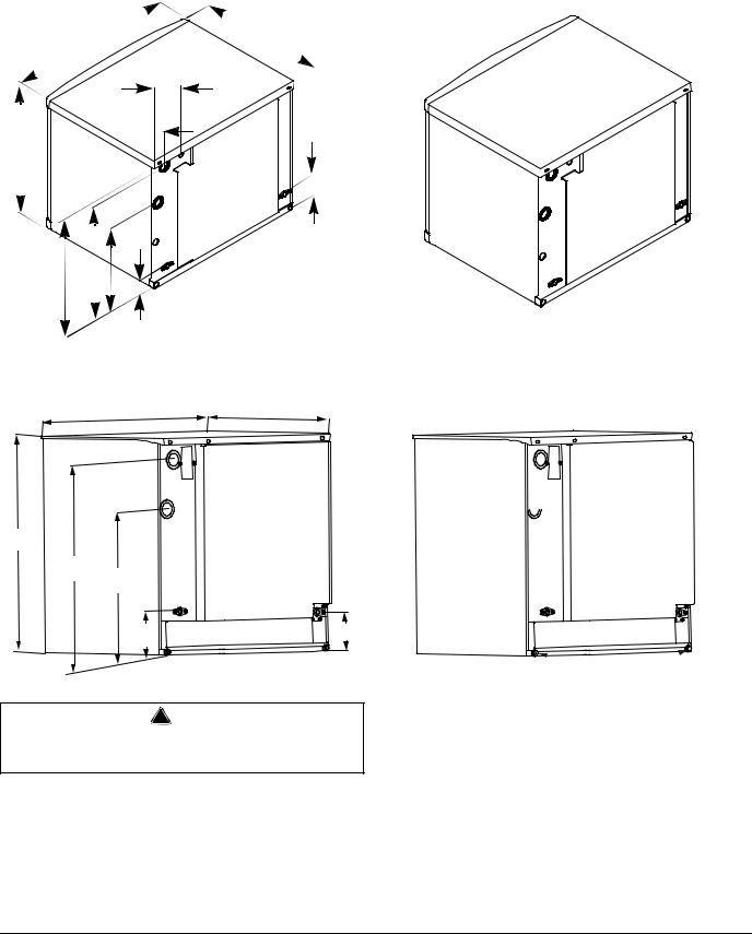
Ice Machine Dimensions
Important
Failure to follow these installation guidelines may affect warranty coverage.
S0600C/S0850C/S1000C/S1200C ICE MACHINES
W 
 D
D
 14.88" (37.80cm)
5.36" (13.61cm)

H
17.14" (43.53cm)
5.00" (12.70cm)
5.75" (14.6cm) 

8.41" (21.36cm)
 8.50" (21.59cm)

10.61" (26.94cm) 

Suction
Liquid Line
Line
Water Inlet |
Electrical |
|
|
3/8” FPT |
|
Drain |
|
1/2” |
|
FTP |
|
|
AuCS |
Base Drain |
Knockout |
|
Ice |
Dimension D |
Dimension W |
Dimension H |
|
Machine |
||||
|
|
|
||
S0600C |
24.5 in |
30 in |
21.5 in |
|
(62.2 cm) |
(76.2 cm) |
(54.6 cm) |
||
|
||||
S0850C |
24.5 in |
30 in |
26.5 in |
|
(62.2 cm) |
(76.2 cm) |
(67.3 cm) |
||
|
||||
S1000C |
24.5 in |
30 in |
29.5 in |
|
(62.2 cm) |
(76.2 cm) |
(74.9 cm) |
||
|
||||
S1200C |
24.5 in |
30 in |
29.5 in |
|
(62.2 cm) |
(76.2 cm) |
(74.9 cm) |
||
|
Stacking Two Ice Machines on a Single Storage Bin
S QuietQube ice machines cannot be stacked. However an adapter is available that allows two S QuietQube ice machines to be placed side by side on 60” Manitowoc F & B style bins.
Part Number 000002477 3/08 |
2-1 |
Installation Instructions |
Section 2 |
|
|
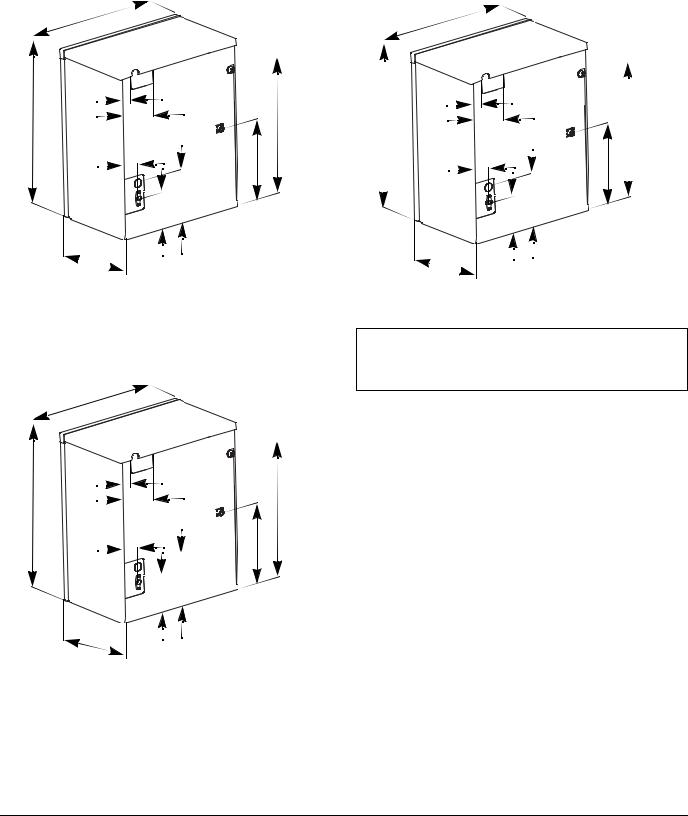
S1470C ICE MACHINES
30” |
24.5” |
(76.2 cm) |
(62.23 cm) |
6.87” (17.45 cm)
3.24” 25” (8.23 cm) 
(63 cm)
14.77” |
|
|
(37.52 cm) |
5.5” |
|
|
|
|
20.96” |
|
(14.0 cm) |
(53.24 cm) |
|
|
21.5” |
2.02” |
|
(54.6 cm) |
|
|
|
(5.13 cm) |
|
S1870C/S2170C ICE MACHINES
30” |
|
25” |
|
(76.2cm) |
|
(63.5cm) |
|
30”
(76.2cm)
26.5”
(67.3cm)
20.5”
(52cm)
6.0” |
5.5” |
|
(14cm) |
||
(15.2cm) |
||
|
! Warning
S1470C/S1870C/S2170C ice machines are not approved for use on Manitowoc B570 series bins.
Electrical
Suction
Line
Water Inlet
3/8” FPT
Liquid
Line
Base
Drain
AuCS
Knockout
Drain
1/2”
FTP
Base Drain
Suction |
Electrical |
Line |
|
Liquid 
Line
Drain |
Water Inlet |
|
1/2” |
||
3/8” FPT |
||
NPTF |
||
|
 Base Drains
2-2 |
Part Number 000002477 3/08 |
Section 2 |
Installation Instructions |
|
|
|
|
Ice Machine Dimensions |
|
|
IB0600C ICE MACHINE |
IB1000C ICE MACHINE |
|
22” |
22” |
|
(55.8 CM) |
||
(55.8 CM) |
||
|
|
3” |
|
|
|
3” |
|
|
|
(7.62 CM) |
|
|
|
|
|
|
|
|
19.5” |
|
(7.62 CM) |
|
|
|
21” |
|
|
|
|
26” |
||
|
|
|
|
|
|||
5.5” |
|
(48.9 CM) |
30.5” |
|
|
||
(54.6 CM) |
|
|
(77.47 CM) |
5.5” |
|
(66 CM) |
|
|
(14 CM) |
|
|
|
|
||
|
|
|
|
|
(14 CM) |
|
|
|
3” |
|
|
|
3” |
|
|
|
(7.62 CM) |
|
|
|
|
|
|
|
|
|
|
(7.62 CM) |
|
|
|
|
|
|
|
|
|
|
|
|
|
|
10” |
|
|
|
17.25” |
|
|
|
(25.4 CM) |
|
|
|
|
|
|
|
|
|
|
(243.81 CM) |
|
|
|
|
|
|
|
|
|
|
5.9” |
8.25” |
|
|
5.9” |
8.25” |
|
|
(21 CM) |
|
|
|
|||
|
(15 CM) |
SV3093 |
|
(21 CM) |
|
||
|
|
|
(15 CM) |
SV3093 |
|||
|
14” |
|
|
|
|
||
|
|
|
|
14” |
|
|
|
|
(35.56 CM) |
|
|
|
|
|
|
|
|
|
|
(35.56 CM) |
|
|
|
|
|
|
|
|
|
|
IB0800C ICE MACHINE
22” (55.8 CM)
|
3” |
|
|
(7.62 CM) |
21.8” |
26.5” |
|
|
5.5” |
(55.4 CM) |
|
(67.31 CM) |
|
|
|
(14 CM) |
|
3”  (7.62 CM)
 12.7” (32.26 CM)
5.9” |
8.25” |
|
|
(21 CM) |
|
||
(15 CM) |
SV3093 |
||
|
14”  (35.56 CM)
Important
Failure to follow these installation guidelines may affect warranty coverage.
Part Number 000002477 3/08 |
2-3 |
Installation Instructions |
Section 2 |
|
|
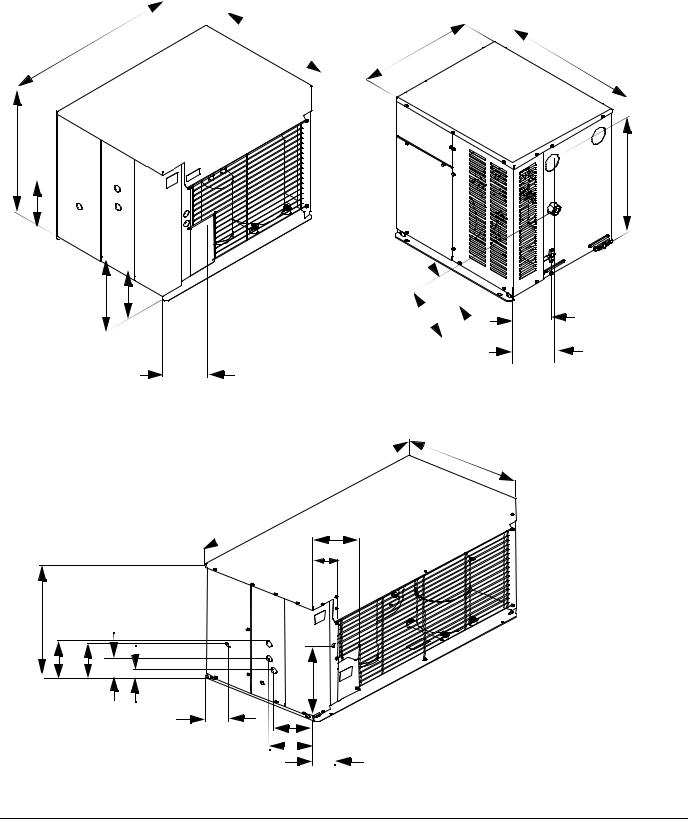
CVD Condensing Unit Dimensions
CVD0675/CVD0885/CVD1085/ CVD1486
CVD1185/CVD1285/CVD1485
34” |
24.13” |
21.87” |
|
(53.7 CM) |
|
||
(86.4 CM) |
|
(55.5 CM) |
24.53” |
|
|
|
(62.3 CM)
25.75” (65.4 CM)
14.5” 


 (36.8 CM)
|
FRONT VIEW |
4.26” |
14.5” |
|
|
(36.8 CM) |
|
(10.8 CM) |
|
12.6” |
8.54” |
9.5” |
(32 CM) |
(21.6 CM) |
(24.1 CM) |
|
|
|
|
8.70” |
10.75” |
|
(22.1 CM) |
SV1758 |
|
|
(27.3 CM) |
|
CVD1885/CVD2085 Air-Cooled |
|
|
|
|
|
|
|
|
26” |
|
|
|
|
(66.04 CM) |
|
|
|
52.5” |
|
|
|
|
(133.35 CM) |
|
|
|
|
11.5” |
|
|
|
|
(28.58 CM) |
|
|
|
|
6.5” |
|
|
|
|
(16.5 CM) |
|
26” |
|
|
|
|
(66.04 CM) |
|
|
|
|
10.25” |
|
|
|
|
(26.04 CM) |
|
|
|
|
|
|
|
14.5” |
FRONT VIEW |
|
|
|
|
|
13.5” |
8” |
|
(36.8 CM) |
|
(34.3 CM) |
|
|
|
|
(20.32 CM) |
|
|
|
|
10” |
|
|
|
|
|
|
|
|
|
(25.4 CM) |
|
5” |
9” |
|
|
|
|
||
|
|
(12.7 CM) |
10” |
|
|
|
|
|
|
|
|
|
5.25” |
PT1307 |
|
|
|
(13.34 CM) |
|
20.64” (52.4 CM)
SV3076
2-4 |
Part Number 000002477 3/08 |
Section 2 |
Installation Instructions |
|
|
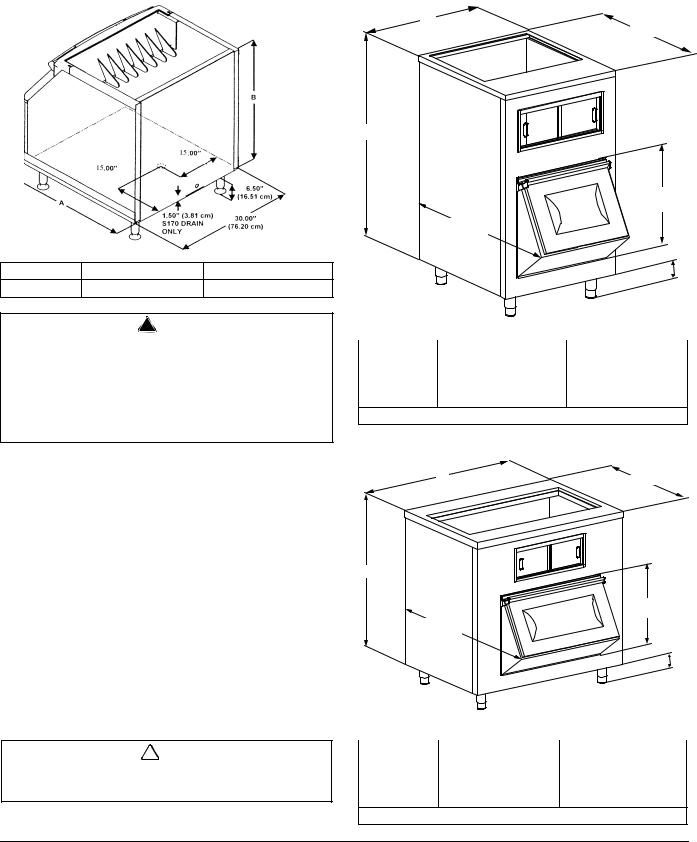
Ice Storage Bin Dimensions
30 INCH (76CM) ICE STORAGE BIN
Bin Model |
Dimension A |
Dimension B |
B570 |
34.0 in (86.3 cm) |
44.0 in (111.7 cm) |
Large Capacity Ice Storage Bin Dimensions
30 INCH (76 CM)
A
34” (86.4 cm)
B
25.25” (64.1 cm)
43.6” (110.81 cm)
6” (15.2 cm)
! Warning
Manitowoc QuietQube ice machines require the ice storage bin to incorporate an ice deflector.
Prior to using a non-Manitowoc ice storage system with other Manitowoc ice machines, contact the manufacturer to assure their ice deflector is compatible with Manitowoc ice machines.
S970 ICE STORAGE BIN
Bin Model |
Dimension A (Width) |
Dimension B |
|
(Height) |
|||
|
|
||
B750 |
30 in. (76.2 cm.) |
58 in. (147.3 cm.) |
|
B1050 |
30 in. (76.2 cm.) |
78 in. (198.1 cm.) |
The bin drain is exactly in the center of the bin.
48 INCH (122 CM) & 60 INCH (152 CM)
A
34” (86.4 cm)
B
25.25” (64.1 cm)
43.6” (110.81 cm)
6” (15.2 cm)
! Caution
30” large capacity bins must be attached to the wall with the bracket provided with the bin.
Bin Model |
Dimension A |
Dimension B |
|
(Width) |
(Height) |
||
|
|||
B1100 |
48 in. (121.9 cm.) |
55.0 in. (139.7 cm.) |
|
B1400 |
60 in. (152.4 cm.) |
55.0 in. (139.7 cm.) |
The bin drain is exactly in the center of the bin.
Part Number 000002477 3/08 |
2-5 |
Installation Instructions |
Section 2 |
|
|
General
These instructions are provided to assist the qualified installer. Check your local Yellow Pages for the name of the nearest Manitowoc distributor, or call Manitowoc Ice, Inc. for information regarding installation and start-up services.
Important
Failure to follow these installation guidelines may affect warranty coverage.
TUBING CAN BE |
TUBING CAN BE |
ROUTED OUT TOP |
ROUTED OUT |
|
BACK OF THE ICE |
|
MACHINE WITH |
|
PROVIDED 90° |
|
ELL’S |
TRIM TOP PANEL WHEN |
|
EXITING TOP |
|
! Warning
PERSONAL INJURY POTENTIAL
Remove all ice machine panels before lifting and installing.
Ice Machine Installation Options
CVD1486 CONDENSER WATER PRESSURE
Water pressure at the condenser cannot exceed 150 psig (10.34 bar) with the standard water-regulating valve. Contact your distributor if your water pressure is greater than 150 psig (10.34 bar). A special order condensing unit is available that allows water pressure up to 350 psig (24.13 bar).
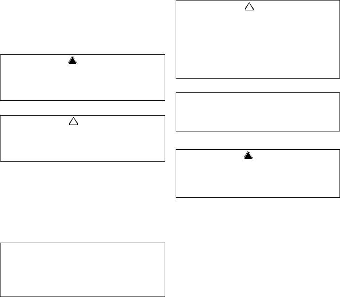
ICE MACHINE HEAD SECTIONS
The ice machine head can be installed with the electrical inlet, water supply inlet and refrigeration tubing entering from the back or top of the ice machine.
The ice machine water drain must exit the back of the ice machine.
TUBING CAN BE ROUTED
OUT BACK OR TOP
SV1752
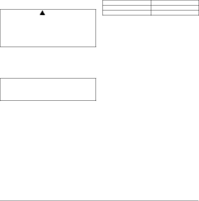
S1470C
TRIM TOP COVER IN THIS AREA
Cut the top cover for top routing of electrical inlet, water supply inlet or refrigeration lines.
1.Prior to cutting, mount top cover onto ice machine.
2.Use ice machine back panel recessed area as a template to mark the underside of the top cover. Do not cut up to or past this line!
3.Using an aviator snips, cut top cover as needed:
A.Do not cut out entire area! Cut up to 1/8 inch to marked line.
B.Cut out only what is needed. (If routing only refrigeration lines out the top, cut just enough to route these lines.)
C.Do not cut out the entire corner area.
2-6 |
Part Number 000002477 3/08 |

Section 2 |
Installation Instructions |
|
|
Ice Machine Head Section Installation Requirements
S600C/S850C/S1000C/S1200C/S1470C/S1870C/S2170C
The location selected for the ice machine must meet the following criteria. If any of these criteria are not met, select another location.
•The location must be free of airborne and other contaminants.
•The air temperature must be at least 35°F (1.6°C), but must not exceed 110°F (43.4°C).
•The location must not be near heat-generating equipment or in direct sunlight.
•The location must not obstruct airflow through or around the ice machine. Refer to ice machine head section clearance requirements.
IB0600C/IB0800C/IB1000C
•Ice/Beverage Ice Machines require the installation of a thermostat to maintain dispenser ice level. The thermostat ships with the ice machine.
•The ice machine head is installed with the electrical inlet, water supply inlet, refrigeration tubing and water drain entering from the back of the ice machine.
•The ice machine head section contains a service loop that must remain installed between the ice machine head section and line set. Sufficient tubing length must be available to allow 180° rotation of the ice machine.
•Maintain a 3” space between the back of the ice machine and the back of the dispenser to allow room for the refrigeration line set service loop.
•The water inlet and electrical connection must contain a service loop to allow future service and maintenance access.
•The drain line must contain a union or other suitable means of disconnection at the ice machine head section.
•The location must be free of airborne and other contaminants.
•The air temperature must be at least 35°F (1.6°C), but must not exceed 110°F (43.4°C).
•The location must not be near heat-generating equipment or in direct sunlight.
•The location must not obstruct airflow through or around the ice machine. Refer to ice machine head section clearance requirements.
Ice Machine Head Section Clearance Requirements
S600C/S850C/S1000C/S1200C/S1470C/S1870C/S2170C
Top 5” (12.7 cm) is recommended for efficient operation and removal of top cover/servicing.
Sides 5” (12.7 cm) is recommended for efficient operation and servicing. There is no minimum clearance required.
Back 3” (7.6 cm) required when routing electrical inlet, water inlet and refrigeration tubing out of the top of the unit.
5” (12.7 cm) required when routing all connections out the back.
IB0600C/IB0800C/IB1000C
Top 2” (5.1 cm) required clearance for cleaning procedures and servicing.
Back 5” (12.7 cm) required when routing all connections out the back.
Sides 8” (20.3 cm) required for servicing.
! Caution
The ice machine head section must be protected if it will be subjected to temperatures below 32°F (0°C). Failure caused by exposure to freezing temperatures is not covered by the warranty. See “Removal from Service/Winterization”.
Part Number 000002477 3/08 |
2-7 |

Installation Instructions |
Section 2 |
|
|
Location of CVD Condensing Unit
The location selected for the CVD Condensing Unit must meet the following criteria. If any of these criteria are not met, select another location.
•The air temperature must be at least -20°F (-28.9°C) but must not exceed 130°F (54.4°C).
•CVD675/CVD1185/CVD2085 Only - The air temperature must be at least -20°F (-28.9°C) but must not exceed 120°F (48.9°C).
•CVD1486 Only- The air temperature must be at least 50°F (10°C) but must not exceed 110°F (43°C).
•The location must not allow exhaust fan heat and/or grease to enter the condenser.
•The location must not obstruct airflow through or around the condensing unit. See below for clearance requirements.
Condensing Unit Clearance Requirements
CVD675/CVD885/CVD1085/CVD1185/CVD2085
Top/Sides
There is no minimum clearance required, although 6” (15.2 cm) is recommended for efficient operation and servicing only.
Front/Back
48” (122 cm)
CVD1285/CVD1485/CVD1885
Top/Sides
There is no minimum clearance required, although 6” (15.2 cm) is recommended for efficient operation and servicing only.
Front
24” (61 cm)
Back
48” (122 cm)
CVD1486 ONLY
Top - 5” (12.7 cm) is required for efficient operation and servicing.
Front/Back/Sides - 12” (30.5 cm)
2-8 |
Part Number 000002477 3/08 |
Section 2 |
Installation Instructions |
|
|
Bin Installation
All ice machines installed on a bin require an ice deflector. Manitowoc bins have a built in deflector that requires no modifications when used with a forward facing evaporator. Ice machines with multiple evaporators require a deflector kit.
Bin adapters or custom bin tops are available to allow installation of a 30” ice machine on a 48” or 60” bin. Refer to ice machine price list for options.
! Warning
Manitowoc QuietQube ice machines require the ice storage bin to incorporate an ice deflector.
Prior to using a non-Manitowoc ice storage system with other Manitowoc ice machines, contact the manufacturer to assure their ice deflector is compatible with Manitowoc ice machines.
LEVELING THE ICE STORAGE BIN
1.Screw the leveling legs onto the bottom of the bin.
2.Screw the foot of each leg in as far as possible.
! Caution
The legs must be screwed in tightly to prevent them from bending.
3.Move the bin into its final position.
4.Level the bin to assure that the bin door closes and seals properly. Use a level on top of the bin. Turn each foot as necessary to level the bin.
THREAD LEVELING
LEG INTO BASE AS
FAR AS POSSIBLE
ADJUST LEGS TO
LEVEL BIN
SV1606
Leveling Leg and Foot
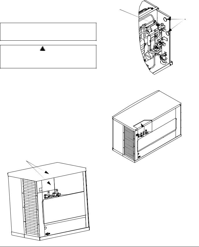
S1470C/S1870C/S2170C INSTALLATION ON A MANITOWOC BIN
! Warning
S1470C/S1870C/S2170C ice machines are not approved for use on Manitowoc S570 series bins.
An ice deflector kit is required for installation. Order appropriate kit (30” or 48”) for your bin.
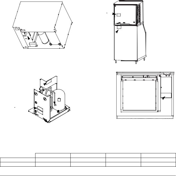
Step 1 Remove the stock ice deflector.
A.Remove the left and right side cover screws
B.Remove the cover to expose four screws, which secure the plastic deflector.
C.Remove fours screws and plastic deflector
D.Install polymer spacer on each side and secure with the four screws.
E.Reinstall cover and screws.
|
REMOVE 1 |
RE-INSTALL TOP |
SCREW ON |
COVER |
EACH SIDE |
|
|
REMOVE |
REMOVE 2 |
DEFLECTOR |
SCREWS |
|
ON EACH |
|
SIDE |
Part Number 000002477 3/08 |
2-9 |
Installation Instructions |
Section 2 |
|
|
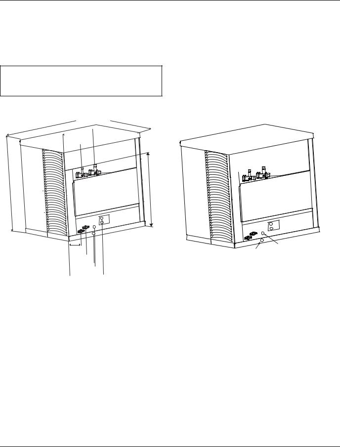
Step 2 Install front support and filler panels.
A.Remove foam tape from front support location.
B.Set front support in place and install foam tape.
C.Position filler panels (align with front support), drill and secure.
D.Install foam tape on front and back. Seal all foam tape edges.
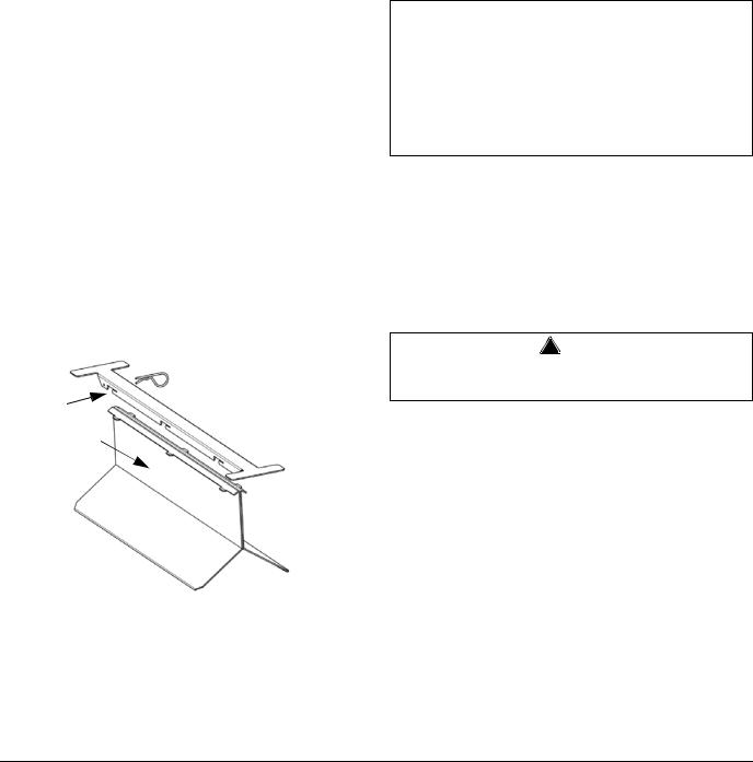
Step 3 Install ice deflector.
A.Locate center of ice machine drop zone (center is 11” from left edge of ice machine to left edge of bracket).
B.Cut and remove foam tape on the front and the back of the bin where the deflector will be located.
C.Remove any residual adhesive; areas must be clean and dry.
D.Remove protective covering from double sided tape on bottom of deflector bracket.
E.Install deflector bracket; Distribute equally to the front and back and locate pin to the rear.
F.Apply foam tape over bracket and seal joints with silicone sealant.
G.Refer to illustration and install deflector in mounting bracket.
2.LOCK IN PLACE WITH PIN
1.SLIDE FORWARD
Dispenser Installation
No deflector is needed for machines that match the size of the dispenser (30” head section on a 30” dispenser) unless required by the dispenser manufacturer. Adapters are required when a smaller ice machine is going on a larger dispenser (22” machine on a 30” dispenser).
IB0600C/IB0800C/IB1000C
Securing the Ice Machine to the Dispenser
Important
Manitowoc Ice/Beverage Ice Machines require an adapter for mounting. Adapters are not included with the ice machine, dispenser or bin and must be ordered separately. When a non-Manitowoc adapter is used, verify the adapter is compatible with Manitowoc Ice/Beverage Ice Machines prior to installation.
The ice machine and adapter plate must be secured to the dispenser to prevent tipping.
•Two holes are located in the front bottom rail of the ice machine, to allow attachment to the adapter plate.
•The adapter cover must be secured to the dispenser to prevent ice from dislodging the cover during agitation.
! Warning
The ice machine and adapter plate must be secured to the dispenser to prevent tipping.
2-10 |
Part Number 000002477 3/08 |
Loading...