


 Manitowoc

Ice Storage and
Transport System
Installation, Use & Care Manual
This manual is updated as new information and models are released.
Visit our website for the latest manual. www.manitowocice.com
This manual contains English and French text
America’s #1 Selling Ice Machine
Part Number 000006529 10/09

Table of Contents
Section 1
General Information
Model Numbers . . . . . . . . . . . . . . . . . . . . . . . . . . . . . . . . . . . . . . . . . . . . . . . . . . . . . 3
Before You Begin . . . . . . . . . . . . . . . . . . . . . . . . . . . . . . . . . . . . . . . . . . . . . . . . . . . 3
Important Warnings and Operating Rules . . . . . . . . . . . . . . . . . . . . . . . . . . . . . . . 3
Section 2
Installation Instructions
Uncrating Cart . . . . . . . . . . . . . . . . . . . . . . . . . . . . . . . . . . . . . . . . . . . . . . . . . . . . . . 4
Uncrating and Installing Base Section . . . . . . . . . . . . . . . . . . . . . . . . . . . . . . . . . . 4
Installing Bin . . . . . . . . . . . . . . . . . . . . . . . . . . . . . . . . . . . . . . . . . . . . . . . . . . . . . . . 4
Installing Tie-down Straps . . . . . . . . . . . . . . . . . . . . . . . . . . . . . . . . . . . . . . . . . . . . 4
Sealing Bin Interior . . . . . . . . . . . . . . . . . . . . . . . . . . . . . . . . . . . . . . . . . . . . . . . . . . 5
Drain Requirements . . . . . . . . . . . . . . . . . . . . . . . . . . . . . . . . . . . . . . . . . . . . . . . . . 5
Plumbing Connections . . . . . . . . . . . . . . . . . . . . . . . . . . . . . . . . . . . . . . . . . . . . . . 5
Affixing Operating Labels . . . . . . . . . . . . . . . . . . . . . . . . . . . . . . . . . . . . . . . . . . . . 5
Door Removal . . . . . . . . . . . . . . . . . . . . . . . . . . . . . . . . . . . . . . . . . . . . . . . . . . . . . . 6
Removing Lower Door Assembly . . . . . . . . . . . . . . . . . . . . . . . . . . . . . . . . . . . 6
Reinstalling Lower Door Assembly . . . . . . . . . . . . . . . . . . . . . . . . . . . . . . . . . . 6
Ice Guide Adjustment . . . . . . . . . . . . . . . . . . . . . . . . . . . . . . . . . . . . . . . . . . . . . . . . 6
Repositioning Ice Guides After Legs Have Been Adjusted . . . . . . . . . . . . . . . . 6
Section 3
Operation
Cart Drain Operation . . . . . . . . . . . . . . . . . . . . . . . . . . . . . . . . . . . . . . . . . . . . . . . . 7
Cart Lids . . . . . . . . . . . . . . . . . . . . . . . . . . . . . . . . . . . . . . . . . . . . . . . . . . . . . . . . . . 7
Ice Transport System Operation . . . . . . . . . . . . . . . . . . . . . . . . . . . . . . . . . . . . . . . 7
Pushing Cart Into Bay . . . . . . . . . . . . . . . . . . . . . . . . . . . . . . . . . . . . . . . . . . . . 7
Loading Ice . . . . . . . . . . . . . . . . . . . . . . . . . . . . . . . . . . . . . . . . . . . . . . . . . . . . 7
Pulling Cart Out . . . . . . . . . . . . . . . . . . . . . . . . . . . . . . . . . . . . . . . . . . . . . . . . . 7
Transporting Ice . . . . . . . . . . . . . . . . . . . . . . . . . . . . . . . . . . . . . . . . . . . . . . . . . 8
Breaking Ice Bridges . . . . . . . . . . . . . . . . . . . . . . . . . . . . . . . . . . . . . . . . . . . . . . . . 8
Baffle Operation . . . . . . . . . . . . . . . . . . . . . . . . . . . . . . . . . . . . . . . . . . . . . . . . . . . . 8
Section 4
Maintenance
Cleaning and Sanitizing Interior Bin . . . . . . . . . . . . . . . . . . . . . . . . . . . . . . . . . . . . |
9 |
Parts Removal for Cleaning/Sanitizing . . . . . . . . . . . . . . . . . . . . . . . . . . . . . . . . . . |
10 |
Shutter Doors and Rails . . . . . . . . . . . . . . . . . . . . . . . . . . . . . . . . . . . . . . . . . . . |
10 |
Drain Tray . . . . . . . . . . . . . . . . . . . . . . . . . . . . . . . . . . . . . . . . . . . . . . . . . . . . . |
10 |
Bin Drain System . . . . . . . . . . . . . . . . . . . . . . . . . . . . . . . . . . . . . . . . . . . . . . . . |
10 |
Cleaning Exterior Bin . . . . . . . . . . . . . . . . . . . . . . . . . . . . . . . . . . . . . . . . . . . . . . . . |
10 |
Section 5 Customer Support
Before Calling For Service Checklist . . . . . . . . . . . . . . . . . . . . . . . . . . . . . . . . . . . 11 Limited Warranty For Ice Storage Bin & Dispensers . . . . . . . . . . . . . . . . . . . . . . 12 Web site: www.manitowocice.com . . . . . . . . . . . . . . . . . . . . . . . . . . . . . . . . . . . . . 12
2 |
Part Number 000006529 10/09 |
Section 1
General Information
Model Numbers
This manual covers the following model:
Ice Storage and Transport System
FC1350
Important
Following installation, please forward this manual to the appropriate operations person.
Before You Begin
After uncrating and removing all packing material, inspect the equipment for concealed shipping damage. If damage is found, notify the shipper immediately.
! Warning
PERSONAL INJURY POTENTIAL
Do not operate equipment that has been misused, abused, neglected, damaged, or altered/modified from that of original manufactured specifications. This appliance is not intended for use by persons (including children) with reduced physical, sensory or mental capabilities, or lack of experience and knowledge, unless they have been given supervision concerning use of the appliance by a person responsible for their safety.
Important Warnings and Operating Rules
Read this manual completely before assembling or operating Ice Transport System and follow warnings and instructions listed below.
! Warning
To avoid damage to Ice Transport System and injury during operation:
•Do not move Ice Transport System once ice machine has been installed
•Anchor flanged feet to floor as instructed on page 4
•Only use paddle provided to assist ice flow
•Only use cart to transport ice and reinstall carefully in bin bay when not in use
! Warning
To avoid injury during operation of unit:
•Keep entire body clear of bin when breaking up ice
•Keep head and face away from paddle handle when breaking up ice
•Lock caster before scooping or shoveling ice from cart and when parked in bay
•Keep floor around Ice Transport System free of ice and water
•Always operate cart at a slow, reasonable speed
For best operation and to ensure delivery of clean, sanitary ice:
•Be sure bin system is level in both directions to provide proper drainage
•Position cart in bay before opening hopper door
•Install charcoal water filter on inlet water for ice machine
•Hang paddle implement in supplied bracket after each use
•Keep paddle clean and in good repair to avoid ice contamination
•Cover ice with cart lid when transporting
•Follow instructions in this manual for bin and cart cleaning and maintenance
•Drain melt water from cart when positioned in bay by opening drain valve
•Keep glass, dirt and other foreign objects out of bin and cart at all times
Part Number 000006529 10/09 |
3 |
Section 2
Installation Instructions
Uncrating Cart
1.Remove paddle from skid by cutting plastic straps.
2.Cut strap holding front axle to skid.
3.Remove wheel chocks from skid at handle end of cart.
4.Roll cart(s) out of base section.
5.Remove tape holding lid to cart.
6.Remove lid storage bracket(s) from inside cart. (Brackets may be installed on left or right side of bin. See Installing Bin section.)
Uncrating and Installing Base Section
1.Remove screws holding flanged feet and tie-down straps to skid and remove skid.
2.Remove packing material from inside of legs and around shutter door.
3.Position base in intended position and adjust feet to level unit in both directions.
4.Mark position of each flanged foot anchoring hole.
5.Move base out of way and install anchors for 1/4" bolts in floor (supplied by others).
6.Reposition unit in intended position and anchor base unit to floor through flanged feet.
! Warning
When leveling, do not extend any leg more than 1" (26 mm) for total leg height no greater than 2.125" (54 mm). Legs must be secured to floor through feet to avoid possible movement and resulting injury.
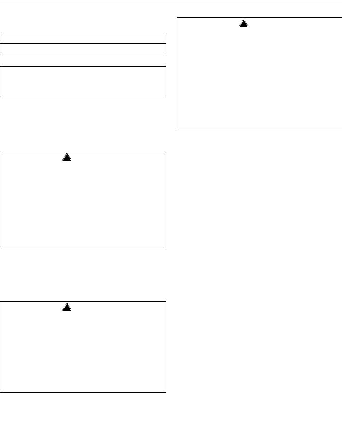
Installing Bin
1.Remove 4 bolts fastening skid to underside of bin.
2.Remove all protective wrap from exterior.
3.Run 1/8" bead of supplied silastic in center of each gasket band on base.
4.Install bin section on base section, taking care that locating pins in base engage holes in bin.
|
BIN |
|
SECTION |
LOCATING PIN |
|
BEAD OF |
BEAD OF |
SILASTIC |
SILASTIC |
GASKET |
GASKET |
|
BASE |
|
SECTION |
5.Use fasteners provided to install paddle support bracket on right or left side of bin in holes provided.
6.Remove paper from back of cart lid storage bracket(s) and position brackets on side of bin.
7.Remove all tape and temporary fastenings from door assemblies and outside of bin.
8.Mount ice machine(s) on top of bin in accordance with ice machine instructions.
9.Install tie-down straps.
Installing Tie-down Straps
! Warning
Tie-down straps to secure bin to base are provided on each side of unit. Straps must be installed to avoid possible injury should unit move. Bolt unit to wall for increased stability, and bolt to floor to prevent side-to-side movement.
1.Remove screws from rivnuts on each side of bin section.
2.Reposition tie-down strap up until slot matches rivnut opening.
3.Reinstall screws in rivnuts and tighten.
4 |
Part Number 000006529 10/09 |
Section 2 |
Installation Instructions |
|
|
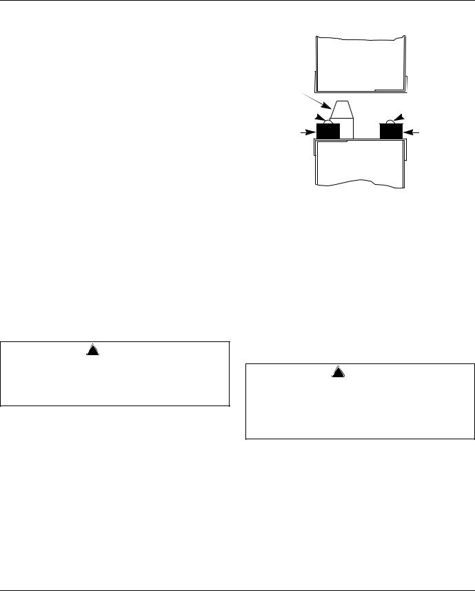
Sealing Bin Interior
! Caution
The joint between base and bin sections must be sealed with silastic to prevent leakage and/or ice contamination and potential voiding of warranty. One or more shutter doors may need to be removed to seal bin.
USE SEALANT PROVIDED TO SEAL
ENTIRE PERIMETER OF SEAM WHERE
BASE AND BIN SECTION JOIN.
1.Support shutter door(s) with one hand and remove thumbscrews from side of shutter door(s) at underside of base.
2.Pivot door(s) downward to remove.
3.Gain access through this opening and seal entire perimeter of seam between bin and base with provided sealant or equivalent.
4.After sealant has set but before shutter door(s) have been reinstalled, clean inside of bin following instructions in this manual.
5.Reinstall shutter door(s).
Drain Requirements
•Bin drain termination must have an air gap.
•Drain lines must have a 1.5 inch drop per 5 feet of run (2.5 cm per meter), and must not create traps.
•The floor drain must be large enough to accommodate drainage from all drains.
•Run separate bin and ice machine drain lines and insulate to prevent condensation.
Plumbing Connections
NOTE: It is recommended that a full width grated floor drain be installed in front of bin.
1.Units are shipped for a right side exiting drain. To drain to left, switch positions of screws in trough brackets from lower hole to upper hole on left bracket and upper hole to lower hole on right bracket.
2.Remove plug from left side of drain trough and insert in right side.
3.Connect drain line to 1-1/4" PVC slip fit drain fitting.
4.Make final connections to ice machine.
Affixing Operating Labels
Operating labels taped to base front educate staff to shutter door operation. If desired, these labels can be affixed permanently by peeling off back paper and affixing in locations desired.
NOTE: Adhesive backing is extremely strong and labels cannot be easily removed once installed.
EXTERIOR |
|
BIN |
|
INTERIOR |
|
SECTION |
|
||
|
|
|
|
|
|
|
|
|
|
|
|
|
|
|
|
|
|
|
|
|
|
BASE |
COMPLETELY |
|
SECTION |
SEAL GASKET |
|
|
|
|
|
|
|
|
|
Cross Section of Ice Transfer System
Sections Joined
Part Number 000006529 10/09 |
5 |
Installation Instructions |
Section 2 |
|
|
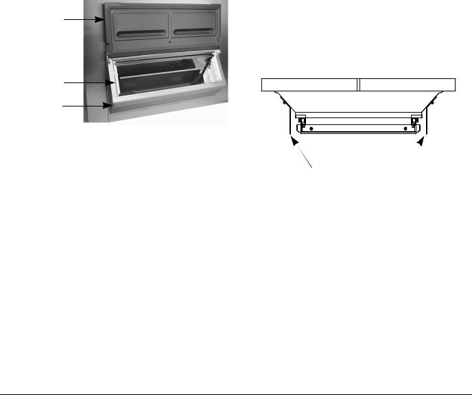
Door Removal
REMOVING LOWER DOOR ASSEMBLY
(Only if required for access through narrow doors)
1.With lower access door closed, remove Phillips head screw and washer from hinge area on each side of lower access door.
2.Insert screwdriver between door and hinge bracket on one side of door and gently push against bracket to provide room for door stud to clear bracket.
3.Remove access door.
4.Pull up on baffle to remove.
5.Remove three or four (3 or 4) screws along top of door assembly.
6.Pull forward on assembly and remove.
ACCESS
DOOR
BAFFLE
LOWER DOOR
ASSEMBLY
REINSTALLING LOWER DOOR ASSEMBLY
1.Reinstall lower door assembly in bin opening.
2.Reinstall three or four (3 or 4) screws in hood at top of door assembly.
3.Reinstall the baffle in side panel tracks and push down to seat.
4.With door closed insert one door stud through hinge bracket.
NOTE: For proper operation the access door must be reinstalled in the closed position.
5.On other side, insert screwdriver between door and hinge bracket and gently push against bracket to provide room for door stud to clear bracket.
6.Reinstall washers and screws in lift door and tighten.
7.Check door to ensure proper operation.
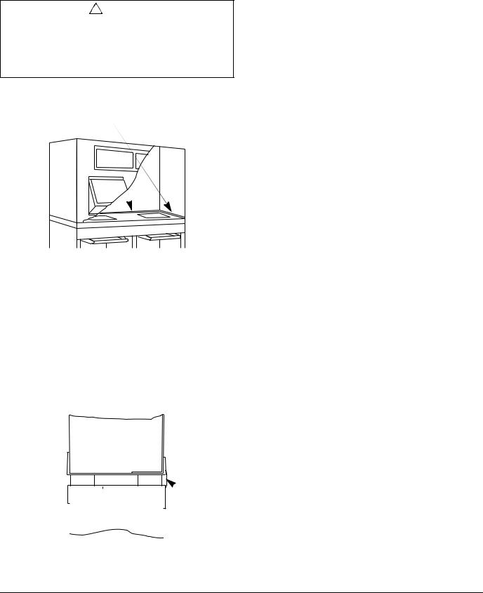
Ice Guide Adjustment
Ice may flow over sides of cart when exiting hopper. Ice guides hang down below hopper and help contain flowing ice inside cart.
Guides are installed in highest position at factory, providing 3/4" (19 mm) clearance to top of cart when legs are in full down position. If legs are adjusted up during leveling of Ice Transport System, ice guides should be lowered to maintain 3/4" (19 mm) clearance. Access to sides of Ice Transport System is required to perform operation.
REPOSITIONING ICE GUIDES AFTER LEGS HAVE BEEN ADJUSTED
1.Position cart (with totes, if so equipped) in bay below shutter door opening.
2.Determine amount guides must be lowered to maintain 3/4" (19 mm) clearance.
3.Remove thumbscrews holding guides.
4.Select hole to reposition guide at proper level and resecure with thumbscrew.
5.Repeat process for each bay in system.
BRACKETS ON UNDERSIDE OF HOPPER
TO WHICH ICE GUIDES ARE SECURED
6 |
Part Number 000006529 10/09 |
Section 3
Operation
Cart Drain Operation
1.Position cart all the way in bay.
2.Lock caster to prevent cart movement.
3.To open drain, pull knob out.
4.To close, push knob in.
PUSH TO CLOSE
Cart Lids
1.Hang cart lids on brackets on bin side when carts are positioned in bay.
2.Remove from bracket and place lid on cart when transporting ice.
3.To avoid placing lid on floor, position lid horizontally on cart lip, resting lid against cart handle when unloading ice from cart.
4.Reinstall lid in bracket on side of bin before placing cart in bay.
Ice Transport System Operation
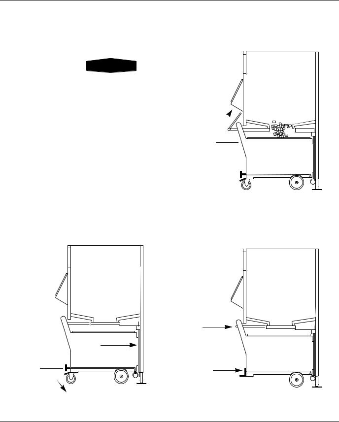
PUSHING CART INTO BAY
1.PUSH cart all the way to back.
2.PULL cart drain open.
3.Lock brake on caster DOWN.
1
2 
3
LOADING ICE
1.PULL shutter handle open.
2.Store handle up against bin.
2 |
1 
PULLING CART OUT
1.PUSH shutter handle closed.
2.PUSH cart drain closed.
3.Release brake on caster.
1
2
3

Part Number 000006529 10/09 |
7 |
Operation |
Section 3 |
|
|
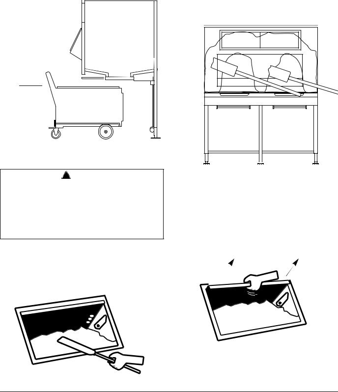
TRANSPORTING ICE
1.PULL cart from base.
2.Place lid on cart.
1 
1.Completely knock down all ice from sides and back of bin.
2.Knock down any bridge that has occurred in middle.
3.Agitate paddle back and forth to break up congealed ice mass.
Breaking Ice Bridges
! Warning
Do not dig up at ice. Instead, break away “legs” that are holding bridges. Ice above will then fall.
To avoid injury, do not attempt to break up bridged ice through upper windows or hopper shutter door. A falling ice bridge can cause paddle to lift. Keep head and face away from paddle handle to avoid injury.
It may be necessary to use the paddle to break up ice bridges that occur along the sides and in the middle of the bin. This often happens if ice has been held in storage for a period of time without use. Use supplied paddle accessory to break up bridges.
Baffle Operation
The baffle can be adjusted and locked at one of several levels to accommodate flow characteristics of different types of ice.
Bin is shipped with the baffle in full down position. The baffle can be raised and locked in higher position for better flow or when more access is needed.
8 |
Part Number 000006529 10/09 |
 Loading...