


UC3503A
T
ECHNICAL INFORMATION
Models No.
UC3003A, UC3503A, UC4003A, UC4503A
PRODUCT
P 1 / 8
Description
Chain saws 300mm, 350mm, 400mm, 450mm
CONCEPT AND MAIN APPLICATIONS
For European market, the above models have been developed
as upgraded chain saws of the current UC3001A series models.
The new UC3003A seies models feature contnuous rating input
of 2000W while the UC3001A series 1800W.
Additionally, the new series includes Model UC4503A,
450mm (18") chain saw which is not in the lineup of UC3001A
series.
Specification
Voltage (V)
230 - 240
Current (A)
8.8 2,000 2,2001,100
Cycle (Hz)
50 / 60
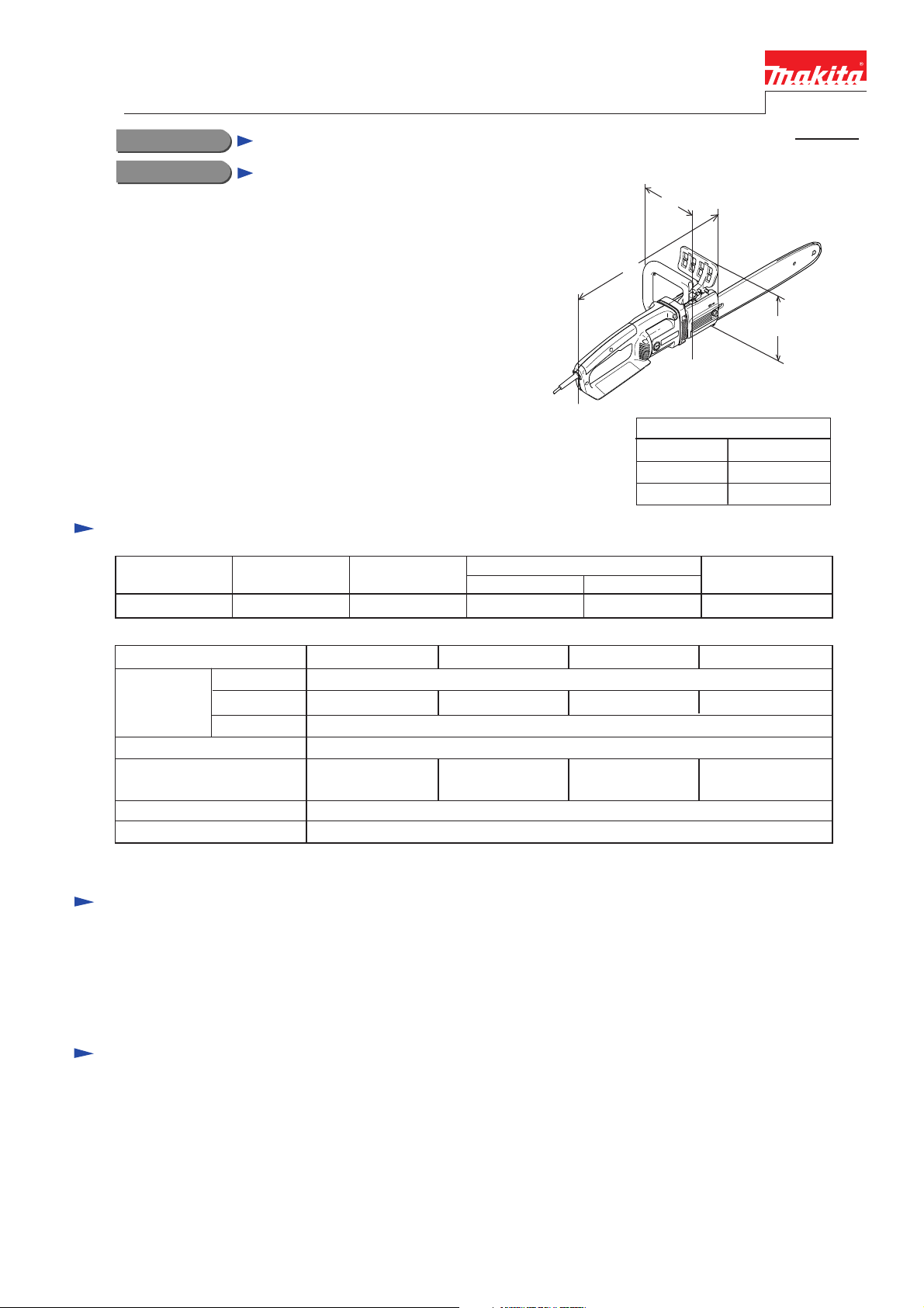
L
Length ( L )
Width ( W )
Height ( H )
Continuous Rating (W)
Input Output
W
H
Dimensions: mm ( " )
470 (18-1/2)
179 (7)
215 (8-1/2)
Max. Output (W)
Model No.
Chain type
Chain blade
No load chain speed: m/s
Guide bar length: mm (")
Electric brake
Clutch
Pitch
Gauge
UC3003A UC3503A UC4503AUC4003A
91VG
3/8" 46 drive links
300
(12)
3/8" 52 drive links 3/8" 56 drive links 3/8" 62 drive links
0.050"
13.3
350
(14)
Yes
Yes
400
(16)
Standard equipment
* Guide bar scabbard .................... 1 pc.
* Wrench ....................................... 1 pc.
< Note > The standard equipment for the tool shown may differ from country to country.
Optional accessories
* Chain blade
* Guide bar
450
(18)
Repair
CAUTION:
First of all, remove the chain blade for your safe repair and maintenance.
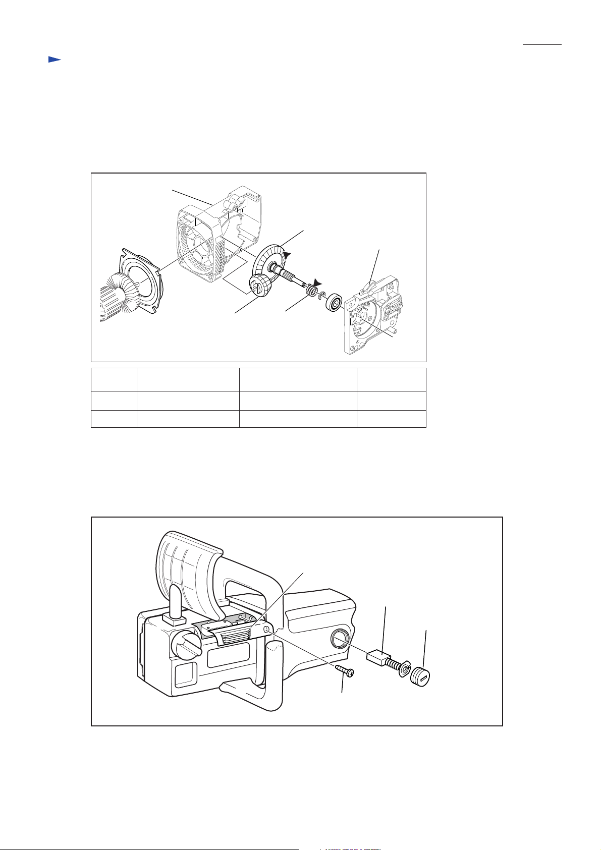
< 1 > Lubrication
Apply Makita grease N. No.1 to the following portions designated by black triangle
to protect parts and product from unusual abrasion. (Fig. 1)
Fig. 1
Gear housing L
(35)
Gear housing R
P 2 / 8
Straight
bevel gear 14
Item No.
(31)
(35) Straight bevel gear 43 Whole part approx. 3.0
Part Name
Worm gear Whole part approx. 1.0
(31)
Portion to be lubricated
Amount: g
< 2 > Removing Gear Housing from Motor Housing for Replacement of Armature Assembly
1. After removing brush holder caps, remove carbon brushes.
Remove a 4x18 tapping screw. Now cover (for switch) can be removed from gear housing L. (Fig. 2)
Fig. 2
Cover (for switch)
Carbon brush
Tapping screw 4x18
Brush holder cap
(to be continued to next page)
P 3 / 8
Repair
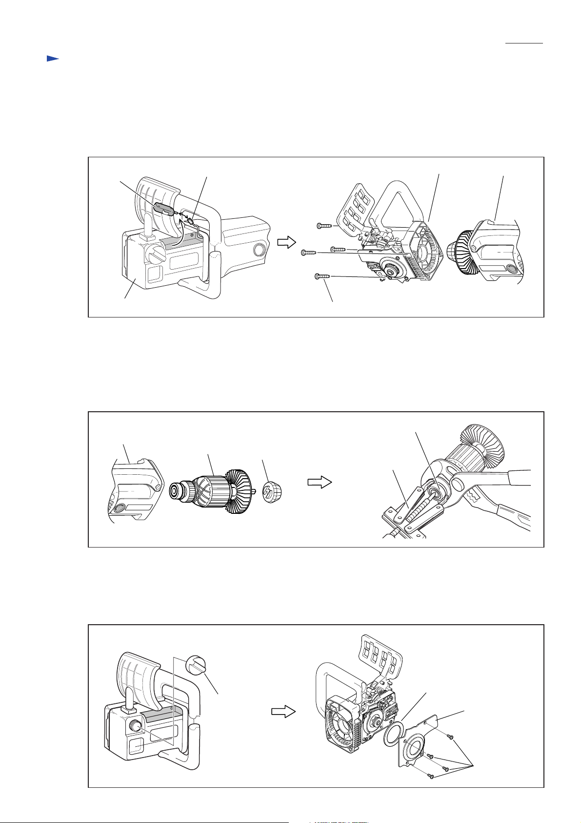
< 2 > Removing Gear Housing from Motor Housing for Replacement of Armature Assembly (cont.)
2. Take switch out of gear housing L, and then disconnect the connecting terminal from switch
as illustrated to left in Fig. 3.
3. Remove four 5x25 tapping screws as illustrated to right in Fig. 3.
Now motor housing can be separated from gear housing section.
Fig. 3
Switch
Gear housing L
4. Replace armature assembly as described below (Fig. 4):
1) After removing motor housing from gear housing, take armature assembly out of motor housing.
2) Remove straight bevel gear 14 from the armature. This gear can be removed by hand.
3) Remove ball bearing 629ZZ on the commutator end of armature assembly using Bearing extractor (No.1R269)
and pliers as illustrated to right in Fig. 4.
Ball bearing 6301LLB on the drive end of armature assembly can be removed in the same way.
Fig. 4
Motor housing
Connecting terminal
Armature
Straight
bevel gear 14
Tapping screw 5x25 (4 pcs)
Bearing extractor
(No.1R269)
Gear housing section
Ball bearing 629ZZ
Motor housing
< 3 > Disassembling Gear Housing
1. Remove oil tank cap, and remove chain oil from oil tank as illustrated to left in Fig. 5.
2. Separate cover plate from gear housing R by removing four BT3.5x9.5 tapping screws as illustrated to right
in Fig. 5.
Fig. 5
Gasket
Oil tank cap
(to be continued to next page)
Cover plate
Tapping screw
BT3.5x9.5
 Loading...