


Makita EG711A, EG511AE, EG781A, EG711AE, EG511A User Manual
...
EG series
EG301A
EG381A, EG381AE EG511A, EG511AE EG711A, EG711AE EG781A, EG781AE
3ZZ9990516
(California Proposition 65)
WARNING:
The engine exhaust from this product contains chemicals known to the State of California to cause cancer, birth defects or other reproductive harm.
(California only)
AIR INDEX
To show compliance with California emission regulations, a hangtag has been provided displaying the Air Index level and durability period of this engine.
The Air Index level defines how clean an engine’s exhaust is over a period of time. A bar graph scaled from “0” (most clean) to “10” (least clean) is used to show an engine’s Air Index level. A lower Air Index level represents cleaner exhaust from an engine.
The period of time (in hours) that the Air Index level is measured is known as the durability period. Depending on the size of the engine, a selection of time periods can be used to measure the Air Index level (see below).
Descriptive Term |
Applicable to Emissions Durability Period |
||
Moderate |
- |
50 hours |
(engine from 0 to 80 cc) |
|
|
125 hours |
(engine greater than 80 cc) |
Intermediate |
- |
125 hours |
(engine from 0 to 80 cc) |
|
|
250 hours |
(engine greater than 80 cc) |
Extended |
- |
300 hours |
(engine from 0 to 80 cc) |
|
|
500 hours |
(engine greater than 80 cc) |
|
|
1000 hours |
(225 cc and greater) |
Notice : This hangtag must remain on this engine or piece of equipment, and only be removed by the ultimate purchaser before operation.
Notice : FEDERAL EMISSION COMPONENT DEFECT WARRANTY and CALIFORNIA EMISSION CONTROL WARRANTY are applicable to only those engines/ generators complied with EPA (Environmental Protection Agency) and CARB (California Air Resources Board) emission regulations in the U.S.A.
Notice : To the engines/generators exported to and used in the countries other than the U.S.A., warranty service shall be performed by the distributor in each country in accordance with the standard engine/generator warranty policy as applicable.

FOREWORD
Thank you for purchasing a Makita generator.
This manual covers operation and maintenance of the Makita generators. All information in this publication is based on the latest production information available at the time of approval for printing.
Pay special attention to statements preceded by the following words:

 DANGER
Indicates a possibility of death or serious injury if instructions are not followed.

 WARNING
Indicates a strong possibility of severe personal injury, loss of life and equipment damage if instructions are not followed.
CAUTION
Indicates a possibility of personal injury or equipment damage if instructions are not followed.
NOTE:
Gives helpful information.
If a problem should arise, or if you have any questions about the generator, consult an authorized dealer or service shop

 WARNING
■The generator is designed to give safe and dependable service if operated according to instructions.
■Do not operate the generator before you have read and understood the instructions. Failure to do so could result in death, personal injury or equipment damage.
ENGLISH

CONTENTS
1.SAFETY PRECAUTIONS 1
2.SPECIFICATIONS 3
3.COMPONENTS 4
4.PRE-OPERATION CHECKS 7
5.OPERATING PROCEDURES 11
6.WATTAGE INFORMATION 21
7.SPARK ARRESTER 23
8.MAINTENANCE SCHEDULE 24
9."HOW-TO" MAINTENANCE 26
10.PREPARATION FOR STORAGE 30
11.TROUBLESHOOTING 31
12.WIRING DIAGRAM 32
1. SAFETY PRECAUTIONS
Please make sure you review each precaution carefully.

 WARNING
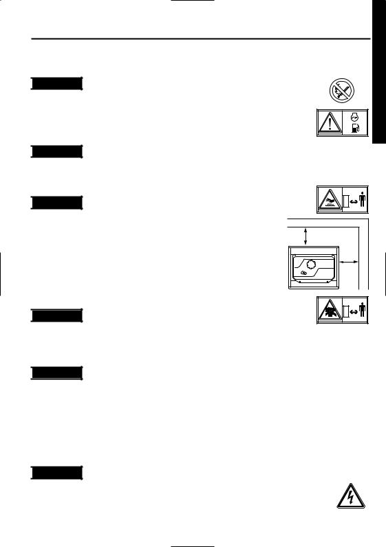
Do not operate the generator near gasoline or gaseous fuel because of the potential danger of explosion or fire.
Do not fill the fuel tank with fuel while the engine is running. Do not smoke or use open flame near the fuel tank. Be careful not to spill fuel during refueling. If fuel is spilt, wipe it off and let dry before starting the engine.

 WARNING
Do not place in flammables near the generator.
Be careful not to place fuel, matches, gunpowder, oily cloths, straw, trash, or any other in flammables near the generator.
ENGLISH

 WARNING
Do not operate the generator inside a room, cave, tunnel, or other insufficiently ventilated area.
Always operate it in a well-ventilated area, otherwise the engine may become overheated, and the poisonous carbon monoxide gas, an odorless, colorless, poison gas, contained in the exhaust gas will endanger human lives.
Operate generator only outdoors and far from open windows, doors, ventilation intakes and other openings.
Keep the generator at least 1 meter (3 feet) away , including overhead, from any structure or building use.
1m |
1m |

 WARNING
Do not enclose the generator nor cover it with a box.
The generator has a built-in forced air cooling system, and may become overheated if it is enclosed. If generator has been covered to protect it from the weather during non use, be sure to remove it and keep it well away from the area during generator use.

 WARNING
Operate the generator on a level surface.
It is not necessary to prepare a special foundation for the generator.
However, the generator will vibrate on an irregular surface, so choose a level place without surface irregularities.
If the generator is tilted or moved during operation, fuel may spill and / or the generator may tip over, causing a hazardous situation.
Proper lubrication cannot be expected if the generator is operated on a steep incline or slope. In such a case, piston seizure may occur even if the oil is above the upper level.

 WARNING
Pay attention to the wiring or extension cords from the generator to the connected device. If the wire is under the generator or in contact with a vibrating part, it may break and possibly cause a fire, generator burnout, or electric shock hazard.
Replace damaged or worn cords immediately.
1

 WARNING
Do not operate in rain, in wet or damp conditions, or with wet hands.
The operator may suffer severe electric shock if the generator is wet due to rain or snow.

 WARNING
If wet, wipe and dry it well before starting. Do not pour water directly over the generator, nor wash it with water.

 WARNING
Be extremely careful that all necessary electrical grounding procedures are followed during each and every use. Failure to do so can be fatal.

 WARNING
Do not contact the generator to a commercial power line. Connection to a commercial power line may short circuit the generator and ruin it or cause electric shock hazard. Use the transfer switch for connecting to domestic circuit.

 WARNING
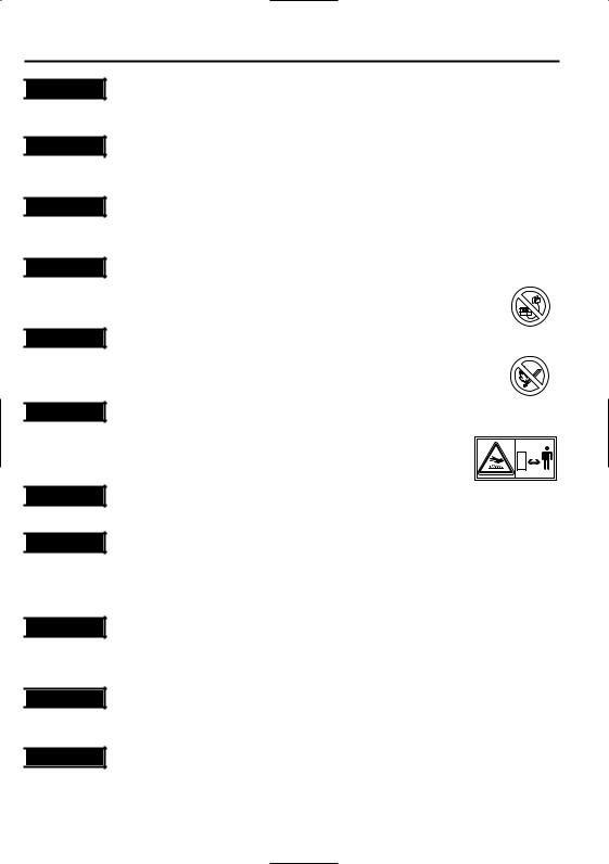
No smoking while handling the battery. The battery emits flammable hydrogen gas, which can explode if exposed to electric arcing or open flame.
Keep the area well-ventilated and keep open flames/sparks away when handling the battery.

 WARNING
Engine becomes extremely hot during and for some time after operation. Keep combustible materials well away from generator area.
Be very careful not to touch any parts of the hot engine especially the muffler area or serious burns may result.

 WARNING
Keep children and all bystanders at a safe distance from work areas.

 WARNING
It is absolutely essential that you know the safe and proper use of the power tool or appliance that you intend to use. All operators must read, understand and follow the tool/appliance owners manual. Tool and appliance applications and limitations must be understood. Follow all directions given on labels and warnings. Keep all instruction manuals and literature in a safe place for future reference.

 WARNING
Use only "LISTED" extension cords.
When a tool or appliance is used outdoors, use only extension cords marked "For Outdoor Use". Extension cords, when not in use should be stored in a dry and well ventilated area.

 WARNING
Always switch off generator's AC circuit breaker and disconnect tools or appliances when not in use, before servicing, adjusting, or installing accessories and attachments.

 CAUTION
Make sure the engine is stopped before starting any maintenance, servicing or repair.
Make sure maintenance and repair of the generator set are performed by properly trained personnel only.
2

2. SPECIFICATIONS
|
|
|
MODEL |
|
EG301A |
|
EG381A |
EG511A |
EG711A |
EG781A |
|
|
|
|
|
EG381AE |
EG511AE |
EG711AE |
EG781AE |
||
|
|
|
|
|
|
|
||||
|
|
Type |
|
|
Brush, self-exciting, 2-poles, single phase |
|||||
|
|
|
|
|
|
|
|
|
|
|
|
|
Voltage regulating system |
|
|
|
|
AVR type |
|
|
|
|
|
|
|
|
|
|
|
|
|
|
|
|
AC Output |
|
|
|
|
|
|
|
|
|
|
|
Rated voltage-Frequency |
V-Hz |
120-60 |
|
|
120/240-60 |
|
|
Generator |
|
|
|
|
|
|
|
|
|
|
|
Rated power factor |
A |
20 |
|
24.2 / 12.1 |
1.0 |
41.7 / 20.8 |
50 / 25 |
||
|
|
|
Rated current |
|
35 / 17.5 |
|||||
|
|
|
Rated output |
VA (W) |
2400 |
|
2900 |
4200 |
5000 |
6000 |
|
|
|
|
|
|
|
|
|
||
|
|
|
Safety device type |
|
|
|
Fuse-less circuit breaker |
|
||
|
|
|
|
|
|
|
|
|
|
|
|
|
DC Output |
|
|
|
|
|
|
|
|
|
|
|
Rated voltage |
V |
|
|
|
12 |
|
|
|
|
|
|
|
|
|
|
|
|
|
|
|
|
Rated current |
A |
|
|
|
8.3 |
|
|
|
|
|
|
|
|
|
|
|
|
|
|
|
|
Safety device type |
|
|
|
Fuse-less circuit breaker |
|
||
|
|
|
|
|
|
|
|
|
|
|
|
|
Model |
|
EX17D |
|
EX21D |
EX30D |
EX35D |
EX40D |
|
|
|
|
|
|
|
|
|
|
||
|
|
Type |
|
ROBIN, Air-cooled, 4-stroke, OHC, Gasoline Engine |
||||||
|
|
|
|
|
|
|
|
|
|
|
|
|
Displacement |
mL |
169 |
|
211 |
287 |
404 |
||
Engine |
|
|
|
|
|
|
|
|||
Fuel tank capacity |
L |
12.8 |
17.8 |
22.0 |
||||||
|
|
Fuel |
|
|
|
Automotive Unleaded Gasoline |
|
|||
|
|
|
|
|
(16.6)*1 |
(21.5)*1 |
(27.5)*1 |
|||
|
|
|
|
|
|
|
|
|
||
|
|
Engine oil capacity |
L |
|
0.6 |
1.0 |
1.2 |
|||
|
|
|
|
|
|
|
|
|
|
|
|
|
Spark plug |
|
|
|
BR-6HS (NGK) |
|
|||
|
|
|
|
|
|
|
|
|
|
|
|
|
Starting system |
|
Recoil |
|
|
Electric starter / Recoil |
|
||
|
|
|
starter |
|
|
|
||||
|
|
|
|
|
|
|
|
|
|
|
|
|
|
|
|
|
|
|
|
|
|
Direction of rotation |
|
|
|
Counter - clockwise |
|
|||||
|
|
|
|
|
|
|
|
|
|
|
Dimension |
Length |
mm |
600 |
|
620 |
675 |
725 |
|||
|
(870)*2 |
(925)*2 |
(975)*2 |
|||||||
|
|
|
||||||||
|
|
|
|
|
|
|
||||
|
|
|
|
|
|
|
|
|
|
|
|
|
Width |
mm |
420 |
|
450 |
510 |
530 |
||
|
|
|
|
|
|
|
|
|
|
|
|
|
Height |
mm |
500 |
|
500 |
570 |
580 |
||
|
|
|
|
|
|
|
|
|
|
|
Dry weight |
kg |
47 |
|
52 |
69 |
86 |
89 |
|||
|
(58)*3 |
(79)*3 |
(96)*3 |
(99)*3 |
||||||
|
|
|
|
|
|
|
||||
Gross weight |
kg |
57(60)*1 |
|
62(65)*1 |
83(86)*1 |
104(108)*1 |
107(111)*1 |
|||
Weight according to EPTA procedure 01/2003 |
|
(68(71))*3 |
(93(96))*3 |
(114(118))*3 |
(117(121))*3 |
|||||
|
|
|
||||||||
Specifications are subject to change without notice.
*1: ( |
) shows the filled amount up to the "LEVEL" position. |
*2: ( |
) shows dimensions with Battery frame. |
*3: ( |
) shows weight with Electric starter. |
ENGLISH
3
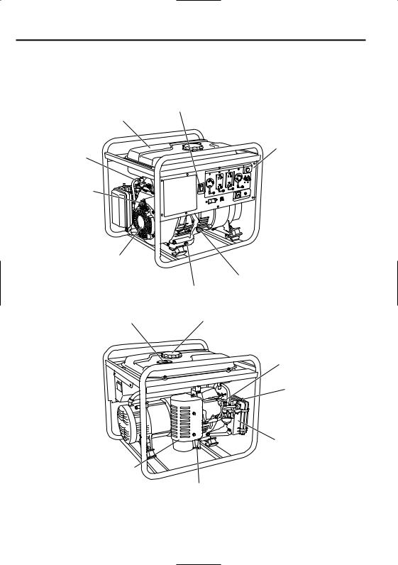
3. COMPONENTS
EG301A, EG381A, EG381AE, EG511A, EG511AE
Fuel tank
Fuel strainer (Fuel valve)
Recoil starter handle
Recoil starter
Fuel gauge
Engine switch
Control panel
Oil gauge (oil filler)
Oil drain plug
Tank cap
Spark plug cap
Choke lever
Air cleaner
Muffler cover
Exhaust outlet
4
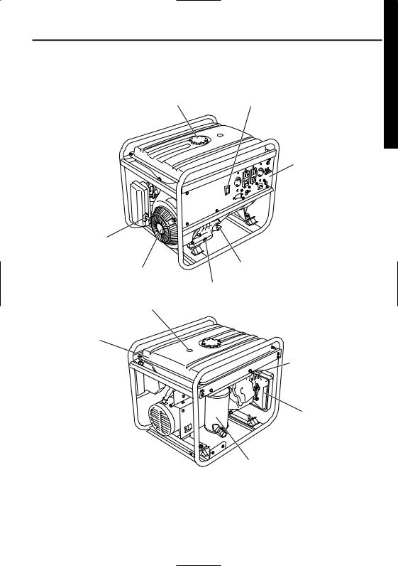
EG711A, EG711AE, EG781A, EG781AE
Tank cap |
Engine switch |
Control panel
Recoil starter handle
Oil gauge (oil filler)
Recoil starter
Oil drain plug
Fuel gauge
Fuel tank
Choke lever

 Spark plug cap
Air cleaner
Muffler
ENGLISH
5
CONTROL PANEL
EG301A |
AC receptacle 20A |
AC circuit |
Pilot lamp |
|
|
breaker |
|
Engine switch |
|
|
DC circuit |
|
|
|
|
|
|
|
breaker |
|
Earth (ground) |
|
DC receptacle |
|
terminal |
|
|
EG381A, EG381AE |
AC receptacle 30A |
AC circuit |
Pilot lamp |
AC receptacle 20A |
breaker |
|
|
[Electric starter model] |
|
|
Idle Control |
|
|
|
|
|
|
|
Switch |
Key switch |
|
|
Full power |
|
|
|
|
|
|
|
switch |
Engine switch |
|
|
DC circuit |
|
|
|
|
|
|
|
breaker |
AC circuit |
Earth (ground) |
|
DC receptacle |
breaker |
terminal |
|
|
EG511A, EG511AE |
AC receptacle 30A |
AC receptacle 30A |
|
EG711A, EG711AE |
|||
EG781A, EG781AE |
AC receptacle 20A |
Pilot lamp |
|
|
|||
[Electric starter model] |
|
|
|
|
|
|
AC circuit |
Key switch |
|
|
breaker |
Engine switch |
|
|
DC circuit |
|
|
|
breaker |
AC circuit |
Full power |
|
DC receptacle |
breaker |
switch |
|
|
|
Earth (ground) terminal |
||
6
4. PRE-OPERATION CHECKS
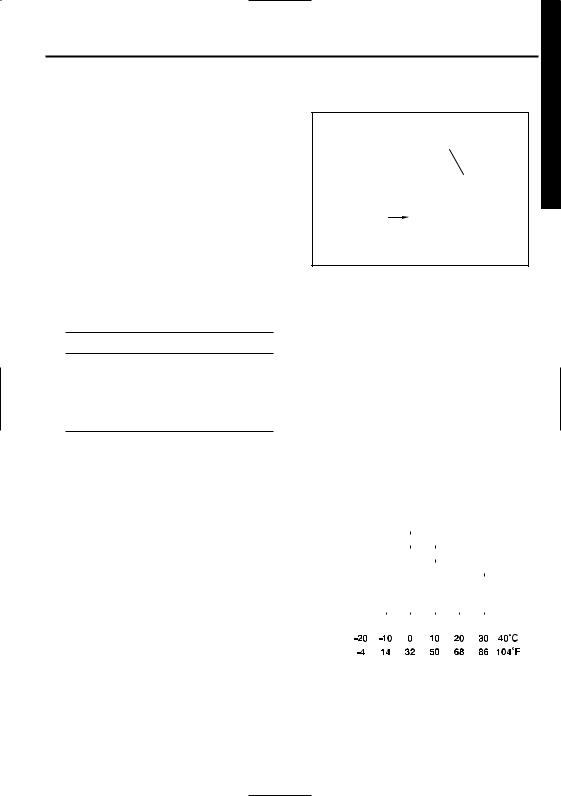
CHECK ENGINE OIL
Before checking or refilling oil, be sure generator is located on stable and level surface with engine stopped.
■Remove oil filler cap and check the engine oil level.
■If oil level is below the lower level line, refill with suitable oil (see table) to upper level line. Do not screw in the oil filler cap when checking oil level.
■Change oil if contaminated. (See "How-To" Maintenance.)
Oil filler cap (Oil gauge)
Upper level 
Lower level
Oil capacity (Upper level) : L (U.S. gal)
EG301A . . . . . . . . . . . . . . . 0.6 (0.15)
EG381A, EG381AE . . . . . . 0.6 (0.15)
EG511A, EG511AE . . . . . . 1.0 (0.26)
EG711A, EG711AE . . . . . . 1.2 (0.32)
EG781A, EG781AE . . . . . . 1.2 (0.32)
Recommended engine oil : |
|
|
|
|
|
|
|
|
|
|
|
|
|
|
|
|
|
|
|
5W |
|
|
|
|
|
|
|
|
|
|
|
|
|||
Use 4-stroke automotive detergent oil |
|
|
|
|
|
|
|
|
|
|
|
|
|
|
|||
|
|
|
|
|
|
|
|
|
|
|
|
|
|
|
|
|
|
|
|
|
|
|
10W |
|
|
|
|
|
|
|
|
|
|||
of API service class SE or higher grade |
|
|
|
|
|
|
|
|
|
|
|
|
|
|
|
|
|
Single grade |
|
|
|
|
|
|
|
20W |
|
||||||||
|
|
|
|
|
|
|
|
|
|
|
|
|
|
|
|
|
|
(SG, SH or SJ is recommended). SAE |
|
|
|
|
|
|
|
#20 |
|
|
|
|
|
|
|
||
|
|
|
|
|
|
|
|
|
|
|
|
|
|
|
|||
|
|
|
|
|
|
|
|
||||||||||
10W-30 or 10W-40 is recommended |
|
|
|
|
|
|
|
|
|
|
|
#30 |
|
|
|
|
|
|
|
|
|
|
|
|
|
|
|
|
|
|
|||||
for general, all-temperature use. If |
|
|
|
|
|
|
|
|
|
|
|
|
#40 |
|
|
||
|
|
|
|
|
|
|
|
|
|
|
|
|
|
|
|
|
|
single viscosity oil is used, select the |
|
|
|
|
|
|
|
|
|
|
|
|
|
|
|
|
|
Multigrade |
|
|
|
|
|
|
|
10W |
-30 |
|
|
|
|
|
|
||
appropriate viscosity for the average |
|
|
|
|
|
|
|
|
|
|
|
|
|
|
|
|
|
|
|
|
|
|
|
|
10W-40 |
|
|||||||||
|
|
|
|
|
|
|
|
|
|||||||||
temperature in your area. |
|
|
|
|
|
|
|
|
|
|
|
|
|
|
|
|
|
Ambient |
|
|
|
|
|
|
|
|
|
|
|
|
|
|
|
|
|
|
temperature |
|
|
|
|
|
|
|
|
|
|
|
|
|
|
|
|
|
|
|
|
|
|
|
|
|
|
|
|
|
|
|
|
|
|
ENGLISH
7
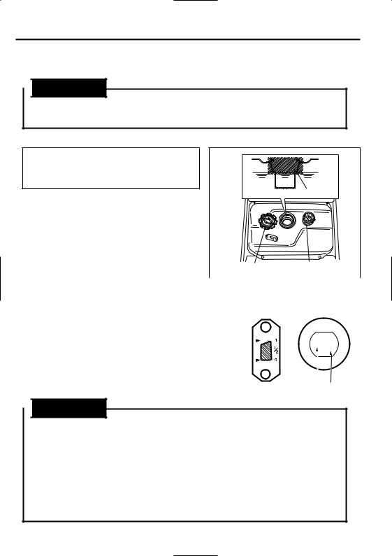
CHECK ENGINE FUEL.

 WARNING
Do not refuel while smoking or near open flame or other such potential fire hazards. Otherwise fire accident may occur.
NOTE :
THIS ENGINE IS CERTIFIED TO OPERATE
ON AUTOMOTIVE UNLEADED GASOLINE.
LEVEL
■ Check fuel level at fuel level gauge.
■ If fuel level is low, refill with unleaded automotive gasoline.
■Be sure to use the fuel filter screen on the fuel filter neck.
|
|
|
Fuel tank cap |
Fuel filter screen |
||||||||||||||
|
|
|
|
|
|
|
|
|
|
|
|
|
|
|
|
|
|
|
|
|
|
|
|
||||||||||||||
Fuel Amount |
|
|
EG301A |
EG711A, EG711AE |
||||||||||||||
|
|
EG381A, EG381AE |
EG781A, EG781AE |
|||||||||||||||
up to "LEVEL" position : |
(L) |
EG511A, EG511AE |
|
|
|
|
||||||||||||
|
|
|
|
|
|
|
|
|
|
|
|
|
|
|
|
|
|
|
EG301A . . . . . . . . . . . . . . . . . . |
12.8 |
|
|
|
|
|
|
|
|
|
|
|
|
|
|
|
|
|
EG381A, EG381AE . . . . . . . . . |
12.8 |
|
FULL |
|
|
|
|
|
|
|
|
|
|
|
|
|
|
|
|
|
|
|
|
|
|
|
|
|
|
|
|
|
|
||||
. . . . . . . . .EG511A, EG511AE |
17.8 |
|
|
|
|
|
|
|
|
|
|
|
|
E |
|
|
F |
|
. . . . . . . . .EG711A, EG711AE |
22.0 |
|
EMPTY |
|
|
|
|
|
|
|
|
|
|
|
|
|
|
|
EG781A, EG781AE |
22.0 |
|
|
|
|
|
|
|
|
|
|
|
|
|
|
|
||
|
|
|
|
|
|
|
|
|
|
|
|
|
|
|
|
|
||
|
|
|
|
|
|
|
|
|
|
|
|
|
|
|
|
|
|
|
|
|
|
|
|
|
|
|
|
|
|
|
|
|
|
EMPTY |
|||
|
|
|
|
|
|
|
|
|
|
|
|
|
|
|
|
FULL |
||
|
|
|
|
|
|
|
|
|
|
|
|
|
|
|
|
|
|
|

 WARNING
Make sure you review each warning in order to prevent fire hazard.
■Do not refill tank while engine is running or hot.
■Close fuel valve before refueling with fuel.
■Be careful not to admit dust, dirt, water or other foreign objects Into fuel.
■Wipe off spilt fuel thoroughly before starting engine.
■Keep open flames away.
8
 Loading...