

Thank you for purchasing a Retracta Auto Rewind Hose
Reel.
The Retracta range of hose reels are a breakthrough in
industrial quality hose reel design, performance,
durability, versatility and cost. The efficiency, safety and
convenience benefits of auto rewind hose reels are
now available for most situations where a hose is
required
Manufactured from the highest quality weather resistant
materials, the tough high impact polypropylene is U.V.
stabilised , designed for all purpose corr osion free
durability. The rewind mechanism is lubricated and
sealed for trouble free operation.
This retractable hose reel promotes a neat and tidy
good-looking work area, reducing the possibility of
accidents, and improves the work environment. Safety is
enhanced by low recoil tension even with the hose fully
extended.
With your appropriate care, combined with the Macnaught
guarantee of dependable after sales service, you will be
assured of cont inu ous safe, eff ici ent and reliable
product operation.
GENERAL INFORMATION
This manual assists you in operating and maintaining
your new retractable hose reel. The information contained
wi ll help y ou e nsu r e ma ny y ear s of depe nda b le
performance and trouble free operation.
Please take a few moments to read through this manual
before installing and operating your new retractable hose
reel. If you experience problems with the product, refer to
the procedures contained within this instruction manual.
If you require further assistance please contact your local
Macnaught distributor, or local Macnaught service centre.
IMPORTANT INFORMATION
This hose reel contains a pre-tensioned spring inside
the drum assembly. For safety reasons the drum
assembly is a non-repairable item. DO NOT under any
circumstances try to open the drum assembly. A new
drum assembl y will be required if the spring is
damaged.
1
RETRACTA (Series 2)
OA100 OXY-ACETYLENE HOSE REEL
0003
RP123
0107
INSTRUCTION MANUAL
Your safety is important to us. Please read, understand
and follow all safety instructions listed below. Some of
these instructions alert you to the potential for personal
injury. “Cautions” listed throughout the manual advise
of potential practices or procedures which may cause
damage to your equipment.
PLEASE READ THIS IMPORTANT SAFETY
INFORMATION CAREFULLY BEFORE USE.
The following additional safety information applies to
the Retracta Oxy-Acetylene Reel. For your safety please
read and follow the safety instructions detailed below.
Oxygen Acetylene Gas is hazardous material that can
cause serio us accide nts and injur ies if proper
precautions and safe practices are not followed.
Op erat ion and ma inte nanc e of Ox y Acet y len e
Gasequipment should conform to the provisions of the
American National Standard Z49-1 “Safety in Welding
and Cutting”.
Make sure all operators have access to adequate
instructions about safe operating and maintenance
procedures.
1
This reel contains a positive latching mechanism,
which enables the reel to be mounted in any position.
Please read and retain this instruction manual to
assist you in the operation and maintenance of this
quality product.
INTRODUCTION
The maximum weight of hose end tools is 2kg (4lb).
The maximum installation height is 4.5 meters (15ft)
above the ground.
DO NOT exceed the maximum working pressure stated
on the product label.
2
DO examine the hose, reel swivel and other equipment
for damage (includ in g leaks) should a “Flashback”
occur. Replacement of swivel seals is recommended.
The use of “Flashback” check valves to reduce the risk of
backflow and “Flashback” is also recommended.
DO use only Retracta replacement swivel components
and seals as supplied by Macnaught. Obtain replacemant
parts from your local Authorised Macnaught Service
Centre or from Macnaught.
DO NOT allow grease and oil to come into contact with
any Oxy-Acetylene equipment, components or hose.
These materials ignite easily and burn violently in the
presence of Oxygen.
DO NOT use pipe fitting compounds or thread lubricants
in making connections.
DO NOT direct the gas flame at the hose or hose reel.
DO NOT exceed the recommended maximum Acetylene
draw off rate from the cylinder and only operate when the
cylinder is upright. Liquid acetone solvent contained in
the cylinder can escape and damage the hose, hose reel
seals and other equipment.
DO NOT work with damaged or faulty equipment or hoses.
INSTALLATION
1) Attach the carry handle to the reel casing above the reel
hose mouth, using the screws provided.
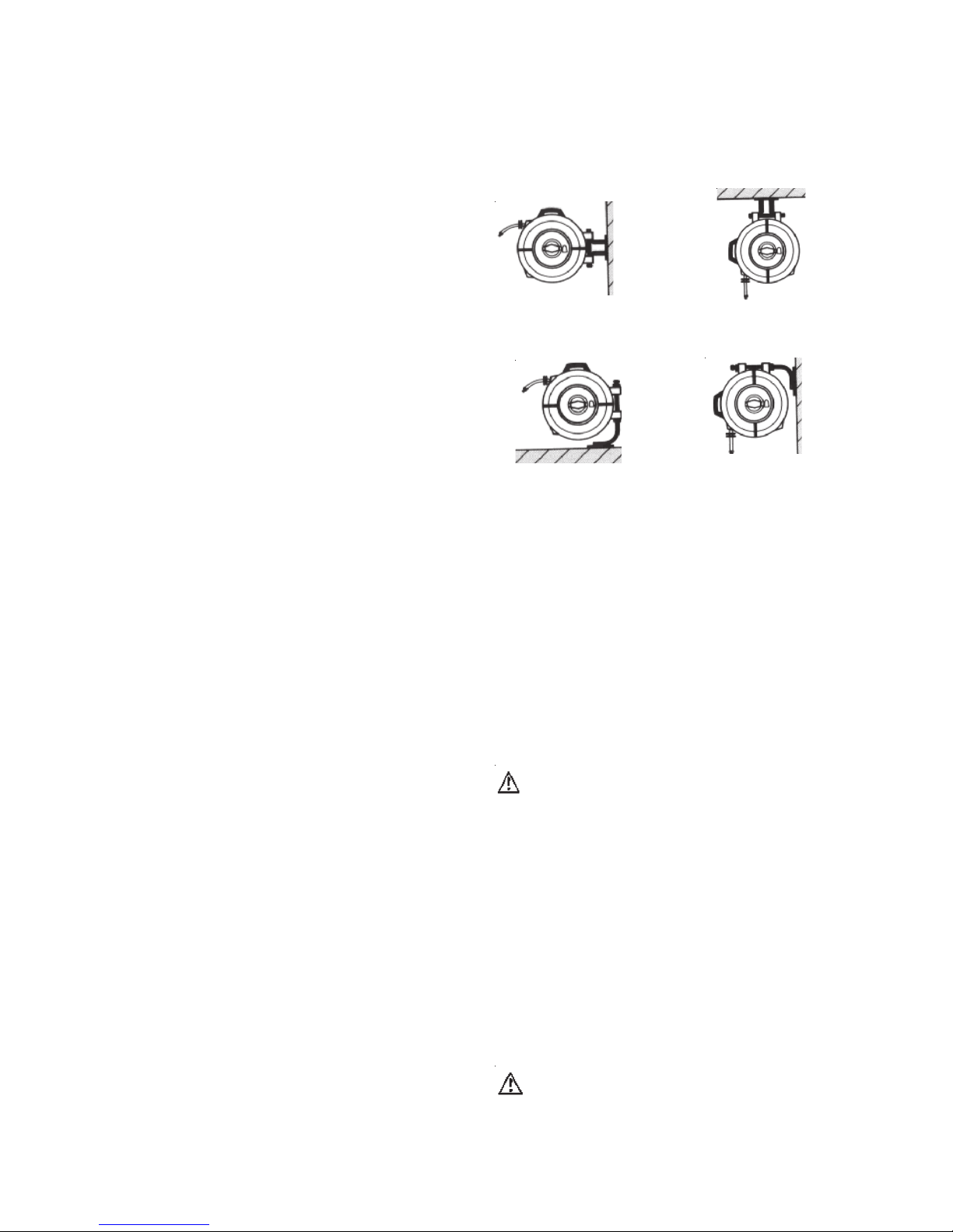
2) The reel can only be mounted in one of the following
positions shown. (Refer Fig 1, 2, 3, 4 )
Fig.1 Wall / BU100 Fig.2 Overhead / BU100
If you choose the most popular positions (1) and (2) you
should use the standard (BU100) bracket. If using
position (3) and (4) you will need the optional
bracket (BB100).
Make all connections dry. DO NOT use pipe fitting
compounds, thread lubricants, oil or grease. Tighten hose
connections with a spanner. Oxygen hoses use only right
hand threaded connections. Note Acetylene hoses use
left hand threaded connections.
CAUTION
Test the system and all connections for leaks prior to
use. Re-test the system frequently (once per month
approx) and on each change of gas cylinder or after
maintenance.
Leak test all connections and hose reel swivels prior
to initial use (refer “Gas Leak Test Procedure”) and
repeat at frequent intervals. It is recommended that
leak tests on all equipment be carried out at least
monthly and on the replacement of cylinders and after
maintenance or replacement of any equipment,
component part or hose.
For O-Ring seal lubrication use only ‘Tranz’ 1434 or an
equivalent inert lubricant when required. DO NOT allow
oil or grease to come in contact with the swivel or
Oxy-Fuel gas equipment.
SAFETY PRECAUTIONS
ONLY use this Retracta reel for the Oxy Acetylene gas
combination.
DO locate equipment in well ventilated areas.
DO run leak tests on your total system including the Hose
Re el Sw ivel freq uent ly. ( R efe r to t h e Re t rac ta
Operating and Service Instructions).
DO repair or replace equipment and hoses immediately
any gas leak is detected. Leaking Oxygen or Acetylene
can cause serious fire and personal injury.
Up to 6ft above ground Up to 15ft above ground
Fig.3 Floor/Bench/BB100 Fig.4 High Wall/BB100
Between 1.8m (6ft) and
4.5m (15ft) above ground
3) Fix mounting bracket in required location and position
reel onto bracket. (Brackets can be padlocked for
additional security). Oxy Acetylene reels should only
be used in well ventilated areas.
4) Connect supply hose to reel inlet allowing sufficient
space for reel to swivel 180° on bracket. Swivel
rotation can be avoided (in the overhead position only)
by adding the locking bracket (RB9) supplied.
POSITIVE LATCH OPERATION
Pull out the hose to the required length.
Note: A clicking noise can be heard every half revolution
of the drum.
To latch the reel, allow the reel to slowly retract after
hearing the 1st, 2nd or 3rd click.
To unlatch the reel, slowly pull out the hose until the
clicking noise stops, then let the hose slowly retract until
the hose stopper rests against the reel mouth.
CAUTION
To prevent injury or damage occurring, do not let go of
the hose during rewinding.

3
3) Rem ove the inl e t side plat e (R efe r Re m ova l/
Replacement Inlet Connection Side Plate).
4) Re mov e circl ip (5) fro m e nd o f s wive l s haft
assembly (1) and slide the inlet shaft from the swivel
body (4).
5) Carefully remove the existing O-Rings by lifting O-Rings
out from grooves using a small screwdriver. With
o-rings extended, cut through the O-Ring onto the
screwdriver face. Be careful you do not score o-ring
grooves.
Do not damage or score inlet shaft surface when
removing or cutting o-ring.
CAUTION
5) Before fitting the new o-rings ensure that both the inlet
shaft and swivel are thoroughly wiped clean. Apply
‘Tranz’ 1434 lubricant (supplied in kit) or equivalent to
the o’ring grooves of the inlet shaft.
6) Slide the o-ring applicator sleeve (supplied in kit) over
the inlet shaft to expose only the furthermost o-ring
groove. Put the first o-ring onto the sleeve and slide up
to the exposed groove. Withdraw the sleeve, stopping
at each groove, and fit the o’rings one at a time
following the same procedure.
SWIVEL RE-ASSEMBLY
7) Slide the inlet shaft back into the swivel body and
replace the circlip. Note that if the circlip groove is not
exposed after fitting, the swivel body is back to front.
GAS LEAK TEST PROCEDURE
Test Oxygen /Acetylene hose lines seperately. Ensure
that all connections from the cylinder through to the torch
are tight.
1) Close both torch valves.
2) Open the Oxygen cylinder valve and adjust the delivery
pressure to 25psi or more.
3) Close the Oxygen valve and observe the delivery
pres sure gaug e. If a drop in pres sur e occ urs,
re-pressure the hose and test all the connections
includi ng the ho se, swiv el and sw ive l bod y by
brushing with warm soapy water solution looking for
the presence of any bubbles.
4) Open the Oxygen valve at the torch and re-close to vent
the Oxygen line. Repeat steps 1, 2 and 3 with the
Acetylene, with the delivery pressure set at 10 psi. Vent
the Acetylene line.
5) Replace or repair any faulty items immediately and
repeat ‘Leak test’ procedure.
MAINTENANCE
This section details the step-by-step procedures that you
may require for the general use and maintenance of your
ree l. Please keep this instruction manual for future
reference.
REMOVAL / REPLACEMENT OF INLET
CONNECTION SIDE PLATE
2) Place reel on a clean bench with the inlet side plate (3)
face up. Remove screw located at the edge of the inlet
plate. Rotate plate clockwise.
4) To replace inlet side plate, suspend reel between your
body and edge of bench. Reposition the plate and turn
counter-clockwise. Relocate side screw.
3) Swivel assembly and hose will come away attached to
the inlet side plate.
SWIVEL SEAL REPLACEMENT
CAUTION
Use only genuine Retracta O-Ring replacement kits. The
use of any other seals can be dangerous. Ensure that
the replacement procedure is carried out in an oil and
grease free, clean environment.
2) Place reel on a clean bench with the inlet side plate (3)
face up. Remove screw located at the edge of the inlet
plate. Rotate plate clockwise.
1) Pull the hose out until it is fully extended and allow the
hose to latch after hearing the 1st, 2nd or 3rd click.
1) Pull the hose out until it is fully extended and allow the
hose to latch after hearing the 1st, 2nd or 3rd click.
8) Slide the inlet shaft back into the drum assembly (6),
pushing the complete unit home.
9) Replace the inlet side plate. (Refer to ‘Removal /
Replacement of Inlet Connection Side Plate’).
HOSE REPLACEMENT
1) Pull the hose out until it is fully extended and allow the
hose to latch after hearing the 1st, 2nd or 3rd click.
2) Remove the inlet side plate (3) (Refer “Removal/
Replacement of Inlet Connection Side Plate”). The
swivel shaft assembly (1) will come away attached
to the inlet side plate.
3) R emo ve ho s e fro m swi vel b ody ( 4). R emov e
remaining old hose from the mouth of the reel.
4) U s e onl y r eco m men ded le ngth a nd typ e o f
replacement hose.
5) Feed the new hose through top of reel mouth and into
opening on reel drum which gives access to the swivel
compartment. Replace and secure the internal hose
stopper 5” (13cm) from the end of hose assembly.
Reconnect hose.
6) Re pla ce inl e t sid e plate (3) (Re fer “R emov al/
Replacement Inlet Connection Side Plate”).

7) Place the reel in a vertical position and while holding
the reel pull the hose out past the last clicking niose
and carefully guide the hose onto the drum
8) If the replacement hose is the same lenght as the old
hose no tension adjustment is necessary. If spring
tension adjustment is required rerer to the “ Spring
tensioning and latch side plate removal” proceedure.
SPRING TENSION AND LATCH SIDE
PLATE REMOVAL
1) Place reel on a clean bench with latching plate (9) face
up.
2) Release spring tension by opening tension plate (8)
and place handle of a pair of pliers in the exposed
slots. Grip the pliers firmly and remove the two screws
holding the tension plate (8) and carefully allow the
tension plate to slowly unwind counter clockwise.
3) Remove screw holding tension plate and remove
tension plate. Remove screw located at the edge of
the latching plate. Turn latching plate clockwise and
remove, this will expose the latching cup assembly.
4) To replace latching plate, suspend reel between your
body and edge of the bench. Reposition the plate and
turn counter clockwise. Relocate side screws, replace
tension plate and fixing screw.
5) Reload spring tension by using the same tool (as in
step 2) and wind tension plate clockwise until hose
sto pper is fir mly aga ins t th e re el mout h, some
resistance will be felt. Then add approximately six (6)
complet 360 deg. tetension turns. Hold the tension
plate in this position align dimples on tension plate la
latching side plate and replace the two screws. Close
CAUTION
Test the reel for leaks prior to any further use
4
CAUTION
Test the reel for leaks prior to any further use.
tension plate and cover.

PARTS LIST
PARTS DIAGRAM
1
2
3
5
6
7
8
9
10
11
12
13
7
5
O A 1 0 0 R E E L P A R T S
I T E M P A R T N o . N o . o f f P A R T o r S E T K I T . R E F D E S C R I P T I O N
1 R S 79 1 R S 79 s ( A U S T ) S W I V E L S H A F T A S S EM B L Y
2 R S 59 1 O A - 1K R S 53 s ( U S A ) S W I V E L S E A L K IT
3 R P 2 1 o r d er R P 3 4 s IN L E T S ID E P L A T E
4 R S 8 0 1 R S 79 s ( A U S T ) S W I V E L B O D Y A S S E M B L Y
5 Z 9 1 Z 9 s C IR C L IP
6 R P 3 5 1 R P 3 5 - B la c k D R U M A S S EM B L Y ( in cl S p ri ng )
7 R P 3 6 1 R P 3 6 C s * i nc l R P 6 s O U T E R C A S IN G ( LO W E R )
7 R P 3 6 s 1 O U T E R C A S IN G i nc l M O U T H G U A R D
8 R P 9 0 1 T E N S IO N I N G P L A T E A S SE M B L Y
9 R P 114 1 R P 3 4 s ( in cl It e m 3 ) L A T C H S ID E P LA T E A S S E M B L Y
10 R P 115 1 R A T C H E T P LA T E
11 R P 6 1 R P 6 s C A R R Y HA N D L E
12 Z 2 2 s 1 R H 3 0 s H O S E ST O P P ER
13 R H 3 0 1 H O SE R E P LA C E M E N T K IT
R B 9 1 R B 9 s L O C K IN G B R A C K E T
B U 10 0 1 B U 10 0 S T A N D A R D W A L L B R A C K ET
* N O M I N A T E C O L O U R W H E N O R D E R I N G R E P L A C E M E N T M O U L D I N G S
4
LATCHING PLATE ASSEMBLY
LATCHING PLATE
LATCH PAWL
SPRING
PLASTIC SLEEVE
USE ONLY genuine Retracta ‘O’ Ring Replacement Kit and lubricant specified. The use of any
other materials can be dangerous.

NOTES:
6

NOTES:
7

TROUBLE SHOOTING GUIDE
1. Hose will not retract
1. Hose bunching.
2. Spring tension too light.
3. Replacement hose too heavy.
3. Reel Leaks.
1. Damaged Hose.
2. Loose fittings.
3. Worn swivel seals
PROBLEM
1. Pull hose out and rewind guiding the hose
to avoid bunching.
2. Refer to “Spring tension and latch side plate
removal”.
3. Replace hose with recommended hose,
refer to “Hose Replacement”.
1. Replace hose. Refer to “Hose Replace
ment”.
2. Tighten Fitting. refer to “Removal / Re
placement of inlet Connection Side Plate”.
3. Refer to “Swivel Seal Replacement”.
REMEDY
8
2. Reel will not latch
1. The hose has been pulled past the
latching teeth.
2. Broken latching pawl or pawl spring.
1. Allow the reel to slowly retract after
hearing the 1st, 2nd or 3rd click.1.
2. Replace broken components. Refer
to “Spring Tension and Latch Side
Plate Removal”.
Macnaught Pty Ltd
PO Box 90 Arncliffe NSW 2205 Australia
Telephone (02) 9567 0401
Facsimile (02) 9597 7773
Email: sales@macnaught.com.au
Web: www.macnaught.com.au
macnaught warranty
1. Macnaught Pty Ltd (“Macnaught”) warrants that all products manufactured by Macnaught and/ or sup plied by
Macnaught under the “Macnaught” brand, exluding M-Series positive displacemnt meters (“Meters”) and components
subject to wear, will be free from any defects caused by faulty materials or workmanship (“Warranty”) for a period of 5
years from the date of purchase of the product.
2. For products (exluding Meters) which carry the “Macnaughtdesign”endorsement, an additional Warranty period of 5 years
applies to all mechanical components (exluding electronic and electrical components), giving a total Warranty period of 10
years.
3. For Meters, the Warranty period is 12 months from the date of purchase of the product.
4. For components contained in all products which are usually subject to wear from normal operation of the products (such
as o-rings, seals, springs, hoses and battaries), the Warranty period is 12 months from the date of purchase of the relevant
product.
5. For products and componenets which are not manufactured by Macnaught and are supplied by Macnaught under a brand
name other than “Macnaught”, the Warranty period is the longer of 12 months from the date of purchase of the relevant
product and the period of the manufacturer’s warranty.
6. The warranties contained in clauses 1, 2, 3, 4 and 5 above are conditional on the purchaser, during the relevant Warranty
period:
a. delivering to Macnaught a detailed notice setting out full details of any defect in any product and
details of the date and place of purchase (together with copies of purchase receipts and/or
other supporting documents), and
b. at the purchaser’s own cost, returning the defective product to the nearest
authorised Macnaught service centre.
7. Subject to compliance by the purchaser with clause 6, Macnaught shall, at its option, repaire or replaice any product
or component found defective by its inspection by reason of faulty materials or workmanship of Macnaught.
8. This Warranty does not cover the failure of products, parts or components which, in the sole judgment of the Macnaught,
arises other than from faulty materials or workmaship of Macnaught, incuding misuse, abrasion,corrosion, negligence,
accident, substitution of non-Macnaught parts, unauthorised modification, improrer use, storage or handling, faulty installation or tampering by the purchaser or any third party.
9. If Macnaught’s inspection discloses no defect in material or workmanship, repair or replacement and return (at
Macnaught’s sole option) will be made at customary charges, which will be advised to the purchaser.
10. Macnaught’s liability and the purchaser’s rights under this Warranty shall be limited to the repair or replacement of
defective products or components and particular, shall not extend to any direct, special, indirect or consequential damage
or losses of any other warranties.
11. The foregoing Warranty supersedes, voids and is in lieu of any other warranties.
This Warranty does not form part of, nor does it constitute, a contract between Macnaught and the end-user or purchaser.
It is additional to any warranty given by the seller of the products. This Warranty does not exlude, limit, ristrict or modify
the non-excludable rights or remedies conferred upon the end-user or purchaser, or the non-excludable duties or liabilities
imposed on the seller or Macnaught, by Part V, Division 2, 2A, and Part VA of the Trade Act1974 (Commonwelth) or other
rights conferred on the end-user or purchaser or duties or liabilities imposed upon Macnaught.
 Loading...