


OWNER’S MANUAL
SAFETY INSTRUCTIONS
1.Read Instructions — All the safety and operation instructions should be read before this Mackie product is operated.
2.Retain Instructions — The safety and operating instructions should be kept for future reference.
3.Heed Warnings — All warnings on this Mackie product and in these operating instructions should be followed.
4.Follow Instructions — All operating and other instructions should be followed.
5.Water and Moisture — This Mackie product should not be used near water – for example, near a bathtub, washbowl, kitchen sink, laundry tub, in a wet basement, near a swimming pool, swamp, or salivating St. Bernard dog, etc.
6.Ventilation — This Mackie product should be situated so that its location or position does not interfere with its proper ventilation. For example, the Component should not be situated on a bed, sofa, rug, or similar surface that may block any ventilation openings, or placed in a built-in installation such as a bookcase or cabinet that may impede the flow of air through ventilation openings.
7.Heat — This Mackie product should be situated away from heat sources such as radiators or other devices which produce heat.
PORTABLE CART WARNING
Carts and stands - The Component should be used only with a cart or stand that is recommended by the manufacturer.
A Component and cart combination should be moved with care. Quick stops, excessive force, and uneven surfaces may cause the Component and cart combination to overturn.
8.Power Sources — This Mackie product should be connected to a power supply only of the type described in these operating instructions or as marked on this Mackie product.
9.Power Cord Protection — Power supply cords should be routed so that they are not likely to be walked upon or pinched by items placed upon or against them, paying particular attention to cords at plugs, convenience receptacles, and the point where they exit this Mackie product.
10.Object and Liquid Entry — Care should be taken so that objects do not fall into and liquids are not spilled into this Mackie product.
11.Damage Requiring Service — This Mackie product should be serviced only by qualified service personnel when:
A.The power-supply cord or the plug has been damaged; or
B.Objects have fallen, or liquid has spilled into this Mackie product; or
C.This Mackie product has been exposed to rain; or
D.This Mackie product does not appear to operate normally or exhibits a marked change in performance; or
E.This Mackie product has been dropped, or its chassis damaged.
12.Servicing — The user should not attempt to service this Mackie product beyond those means described in this operating manual. All other servicing should be referred to the Mackie Service Department.
13.Do not remove the cover on the console. It is permissible to remove the outer cover on the Remote CPU to install accessory cards. Do not remove the inner power supply cover.
14.To prevent electric shock, do not use this polarized plug with an extension cord, receptacle, or other outlet unless the blades can be fully inserted to prevent blade exposure.
Pour prévenir les chocs électriques ne pas utiliser cette fiche polariseé avec un prolongateur, un prise de courant ou une autre sortie de courant, sauf si les lames peuvent être insérées à fond sans laisser aucune pariie à découvert.
15.Grounding or Polarization — Precautions should be taken so that the grounding or polarization means of this Mackie product is not defeated.
16.This apparatus does not exceed the Class A/Class B (whichever is applicable) limits for radio noise emissions from digital apparatus as set out in the radio interference regulations of the Canadian Department of Communications.
ATTENTION —Le présent appareil numérique n’émet pas de bruits radioélectriques dépassant las limites applicables aux appareils numériques de class A/de class B (selon le cas) prescrites dans le règlement sur le brouillage radioélectrique édicté par les ministere des communications du Canada.
FCC Information
NOTE: This equipment has been tested and found to comply with the limits for a Class A digital device, pursuant to Part 15 of the FCC Rules. These limits are designed to provide reasonable protection against harmful interference when the equipment is operated in a commercial installation. This equipment generates, uses, and can radiate radio frequency energy and, if not installed and used in accordance with the instruction manual, may cause harmful interference to radio communications. Operation of this equipment in a residential area is likely to cause harmful interference in which case the user will be required to correct the interference at his own expense.
WARNING — To reduce the risk of fire or electric shock, do not expose this appliance to rain or moisture.

Note: The following notice concerns the lithium battery located on the motherboard inside the Remote CPU.
CAUTION: DANGER OF EXPLOSION IF BATTERY IS INCORRECTLY REPLACED. REPLACE ONLY WITH THE SAME OR EQUIVALENT TYPE RECOMMENDED BY THE MANUFACTURER. DISPOSE OF USED BATTERIES ACCORDING TO THE MANUFACTURER’S INSTRUCTIONS.
ATTENTION: IL Y A DANGER D’EXPLOSION S’IL Y A REMPLACEMENT INCORRECT DE LA BATTERIE, REMPLACER UNIQUEMENT AVEC UNE BATTERIE DU MEME TYPE OU D’UN TYPE ÉQUIVALENT RECOMMANDÉ PAR LE CONSTRUCTEUR. METTRE AU REBUT LES BATTERIES USAGÉES CONFORMÉMENT AUX INSTRUCTIONS DU FABRICANT.
Statement of Conformity
Mackie Designs’ Digital 8•Bus has been tested and conforms to the following standards and directives of the European Council:
73/23/EEC |
Low Voltage Directive with amendments |
|||||
|
91/263/EEC, 89/392/EEC, and 89/336/EEC |
|||||
89/336/EEC |
EMC Directive |
|||||
IEC 950(1991)/EN60950:1992 |
Electrical Safety Requirements |
|||||
EN55103-1 and EN55103-2 |
Residential (E1) and Commercial (E2) Environments |
|||||
|
|
|
|
|
|
|
|
|
|
|
|
|
|
|
|
|
|
|
|
|
|
|
|
|
|
|
|
|
|
|
|
|
|
|
Part No. SW0047 Rev. A 5/03
©2003 Mackie Designs Inc. All Rights Reserved.
Table of Contents |
|
Preface .................................................................................................................................... |
1 |
Chapter 1: Getting Ready ................................................................................................. |
3 |
Introduction .................................................................................................................................................................... |
4 |
About This Manual ............................................................................................................................................ |
4 |
Let’s Get It Working .......................................................................................................................................... |
4 |
Hooking Stuff Up ............................................................................................................................................... |
4 |
A New Way of Thinking: Four Consoles in One!................................................................................... |
7 |
Fader Bank Selection........................................................................................................................................ |
8 |
Let’s Get Some Sound Happening .............................................................................................................. |
8 |
Figure 1-1 Completing the Microphone Signal Path ....................................................................................................... |
9 |
Signal Routing Concept ................................................................................................................................ |
10 |
Figure 1-2 Simple Microphone Connection/Basic Live Setup ................................................................................... |
11 |
Figure 1-3 Setting Up to Track ................................................................................................................................................ |
11 |
Figure 1-4 Basic Mixdown Setup .......................................................................................................................................... |
12 |
Keep Close Track of These Concepts ...................................................................................................... |
12 |
Figure 1-5 Signal-Flow Diagram ............................................................................................................................................. |
13 |
Figure 1-6 D8B Block Diagram ............................................................................................................................................... |
14 |
Figure 1-7 D8B Gain Structure Diagram ............................................................................................................................. |
16 |
Specifications.................................................................................................................................................... |
17 |
Physical Dimensions ....................................................................................................................................... |
18 |
Updating Software .......................................................................................................................................... |
19 |
Windows-based Computers .................................................................................................................................................. |
19 |
Macintosh Computers ............................................................................................................................................................. |
19 |
Summary ............................................................................................................................................................ |
20 |
Chapter 2: Where Is it? ..................................................................................................... |
21 |
It’s Time to Locate Everything… ............................................................................................................................ |
22 |
Rear Panel Description ............................................................................................................................................. |
22 |
Channels 1–12 Inputs ...................................................................................................................................... |
22 |
Channels 13–24 Inputs ................................................................................................................................... |
22 |
Card Cage Section ........................................................................................................................................... |
22 |
Master Input/Output Section ................................................................................................................... |
23 |
AUX OUT Section ........................................................................................................................................... |
24 |
Remote CPU Description......................................................................................................................................... |
25 |
Data and Synchronization I/O .................................................................................................................. |
25 |
Connecting a Mouse, Keyboard and SVGA Monitor......................................................................... |
25 |
Other Connections ......................................................................................................................................... |
25 |
Control Surface Functions ..................................................................................................................................... |
26 |
Channel Strip Section ................................................................................................................................... |
26 |
Master Section Description .................................................................................................................................. |
28 |
Master Fader/Bank Select Section ......................................................................................................... |
28 |
Master V-Pot Section .................................................................................................................................... |
29 |
V-Pot Assign Section ...................................................................................................................................... |
30 |
Figure 2-1 Aux Sends 1-8 (Default – Mackie Stereo Effects [4 MFX Cards]) ......................................................... |
31 |
Fat Channel Section........................................................................................................................................ |
32 |
Studio/Solo Section ...................................................................................................................................... |
33 |
Phones/Cue Mix Section ............................................................................................................................. |
34 |
D8B Manual • Table of Contents • page i
Control Room Section .................................................................................................................................. |
34 |
Clipboard Section ........................................................................................................................................... |
35 |
Master L–R/Shortcuts Section ................................................................................................................. |
36 |
Bus Assignment Section................................................................................................................................ |
36 |
Automation Section ....................................................................................................................................... |
36 |
Session Setup Section ................................................................................................................................... |
38 |
Transport Section ............................................................................................................................................ |
39 |
Chapter 3: What’s On TV?................................................................................................ |
41 |
Using the Graphic User Interface (GUI) ............................................................................................................. |
42 |
The Beauty of It… ............................................................................................................................................. |
42 |
The Master Strip .............................................................................................................................................. |
47 |
Signal Path Flexibility .................................................................................................................................... |
49 |
May I See A Menu Please ......................................................................................................................................... |
51 |
The File Menu ................................................................................................................................................... |
51 |
The Edit Menu................................................................................................................................................... |
53 |
The Channel Menu .......................................................................................................................................... |
56 |
The Options Menu ......................................................................................................................................... |
60 |
Automation Sub-menu ............................................................................................................................................................ |
61 |
Transport Sub-menu ................................................................................................................................................................. |
61 |
Meters Sub-menu ..................................................................................................................................................................... |
62 |
The Plugins Menu ............................................................................................................................................ |
63 |
The Windows Menu........................................................................................................................................ |
65 |
The Desktop Window (Ctrl+D) ............................................................................................................................................ |
66 |
The Setup Window (Ctrl+1) .................................................................................................................................................. |
66 |
General ............................................................................................................................................................................... |
66 |
Network.............................................................................................................................................................................. |
66 |
Digital I/O ......................................................................................................................................................................... |
67 |
Licensing ............................................................................................................................................................................. |
68 |
Mix Options ...................................................................................................................................................................... |
69 |
Surround ............................................................................................................................................................................. |
70 |
MIDI ...................................................................................................................................................................................... |
71 |
FTP Server ........................................................................................................................................................................... |
71 |
The Snapshot Window (Ctrl+2) ............................................................................................................................................ |
71 |
The Surround Window (Ctrl+3) ............................................................................................................................................ |
73 |
The Locator Window (Ctrl+4) .............................................................................................................................................. |
77 |
The Mix Editor Window (Ctrl+5) ........................................................................................................................................ |
79 |
The Fat Channel Window (Ctrl+6) ..................................................................................................................................... |
84 |
The Panning Window (Ctrl+7) .............................................................................................................................................. |
89 |
The Faders Window (Ctrl+8) ................................................................................................................................................ |
90 |
Event Automation Track (Ctrl+9) ........................................................................................................................................ |
90 |
Track Sheet (Ctrl+T) ................................................................................................................................................................. |
92 |
The History List Window (Ctrl+H) ...................................................................................................................................... |
92 |
The MIDI Map Window (Ctrl + –) ...................................................................................................................................... |
93 |
Erase UFX Memory... ................................................................................................................................................................ |
94 |
Upgrade UFX Cards... ............................................................................................................................................................... |
94 |
D8B Manual • Table of Contents • page ii
Chapter 4: Applications .................................................................................................. |
95 |
Setting Up for a Session .......................................................................................................................................... |
96 |
Listening Environment .................................................................................................................................. |
96 |
Channel Configuration/Planning............................................................................................................. |
96 |
Power-up Procedure ...................................................................................................................................... |
96 |
Figure 4-1 Power-up Procedure ............................................................................................................................................ |
96 |
Figure 4-2 Basic Connection for Multitrack Recording .............................................................................................. |
97 |
Setup Window .................................................................................................................................................. |
97 |
Installation and Connection of Optional I/O and Effects Cards ............................................. |
99 |
Installation of FX Cards .............................................................................................................................. |
100 |
Installation of I/O Cards ............................................................................................................................ |
101 |
Checklist for Basic Operational Functionality .................................................................................. |
102 |
Connecting Analog Multitrack(s) ............................................................................................................ |
102 |
Connecting ADAT (Lightpipe) Multitrack(s) ....................................................................................... |
102 |
Connecting TASCAM (TDIF) Multitrack(s) ........................................................................................... |
103 |
Multitrack Recording .................................................................................................................................. |
104 |
Multitrack Tracking Checklist ............................................................................................................................................ |
105 |
Sample Tracking Setup ............................................................................................................................... |
108 |
Mixdown Setup .............................................................................................................................................. |
110 |
Effects/Plug-ins .............................................................................................................................................. |
112 |
Dynamics and EQ Applications ................................................................................................................ |
114 |
MIDI and the D8B ........................................................................................................................................... |
115 |
Word Clock and the D8B – The Kitchen Sync ................................................................................... |
116 |
Dither - To UV22 or Not to UV22: That Is the Question ........................................................................................... |
119 |
D8B–HDR24/96 Setup ............................................................................................................................... |
120 |
Using the Digital 8•Bus with ADATs ....................................................................................................... |
125 |
Connecting the Digital 8•Bus to a BRC and ADATs ......................................................................... |
126 |
Connecting the Digital 8•Bus to ADATs Using an External Sync Box ....................................... |
128 |
Connecting the D8B to TASCAM MDMs ............................................................................................. |
130 |
Digital Audio Workstation Setup ........................................................................................................... |
132 |
Live Sound/Live Recording Setup ......................................................................................................... |
134 |
Post-Production Setup ................................................................................................................................ |
136 |
Bouncing/Summing Using Bus Outs ..................................................................................................... |
136 |
Using Basic Automation.............................................................................................................................. |
137 |
Automation Procedural Checklists ....................................................................................................... |
140 |
Appendices ........................................................................................................................ |
141 |
Appendix A: Service ................................................................................................................................................. |
142 |
Appendix B: IVL Vocal Studio .............................................................................................................................. |
144 |
About the IVL Vocal Studio ....................................................................................................................... |
144 |
The Interface ................................................................................................................................................... |
144 |
Operation–Harmony ................................................................................................................................... |
146 |
Operation–Pitch Correction Mode ....................................................................................................... |
150 |
Appendix C: Plug-in Configuration and Routing .......................................................................................... |
152 |
Appendix D: Shortcuts........................................................................................................................................... |
160 |
Appendix E: MIDI Implementation Guide ...................................................................................................... |
163 |
Appendix F: HUI Mode ........................................................................................................................................... |
164 |
Appendix G: Compatible Cables ....................................................................................................................... |
180 |
Colophon ...................................................................................................................................................................... |
191 |
Index................................................................................................................................... |
182 |
D8B Manual • Table of Contents • page iii
Preface
The Mackie Digital 8•Bus is an amazing digital audio tool. Its flexibility, depth, and power provide the engineer/artist with nearly limitless creative freedom to produce top quality work.
The D8B v5.1 upgrade offers a host of new features that can make your mixes sound better and speed your workflow. Here’s a list of the newest features of the Mackie OS v5.1.
WHAT'S NEW WITH v5.1
•Great new overview screen graphics improve viewing and productivity
•HTML on-screen Help to quickly answer questions about D8B features and functions
•HUI Mode allows the D8B to operate as a HUI control surface with DAW software applications that support the Mackie HUI (i.e., Pro Tools, DP3, Nuendo, Cubase SX, Soundscape, Logic 6)
•New metering options offer more flexibility:
°On-screen level meters with choice of bottom view, top view, or off
°On-screen level Meter Type options include Pre Fader, Post Fader, and Post Mute/Fader
°On-screen level Meter Reference Point can be assigned to –10 dB, –15 dB, or –20 dB to accommodate different program sources
°Show Meters In Trim Mode displays the actual signal level in the on-screen meters when in Trim Levels Automation mode
°Show Peak Holds causes the Overload indicators in the Top meters view to remain lit when triggered by a transient peak
•Numeric Fader Reference—the fader’s current level in dB appears just below the fader
•Modify Fader Levels calibrated in dB
•Vertical channel linking
•Individual Aux Send mutes on each channel
•Stereo Aux Send Pan sliders
•Channel EQ window dims when the EQ is disabled instead of flat-lining
•Double-click the channel EQ window to open the Fat Channel for detailed editing
•Improved Fat Channel:
°Improved EQ algorithms
°Larger Channel EQ and Dynamics EQ views by double-clicking in either graphic window
°Expanded Dynamics View opens graphic views of the Compressor and Gate parameters
°Alternate view of the Compressor and Gate meters
°Compressor meter switches between Output Level or Compressor Gain Reduction
°Gate meter switches between Input Level and Gate Gain Reduction
°Gate Expansion mode allows reduction of the signal level below the designated threshold by a variable ratio
°Adjustable Dynamics Key Types provides a selection of four EQ types that can be applied to the Key Input (BAND 4 EQ TO DYN)
°External MIDI Trigger for the Gate
°Channel polarity can be flipped from the console VFD
•Advanced Mix Editor features including:
°Insert Event by placing Event markers in the Mix Editor window time bar
°Event markers can be moved, edited, and locked
°Events can be commited to Dynamic Automation for further editing
•Independent control of Plug-in Source and Destination
•Plug-in Chaining
•Plug-ins can now be used on Bus Inserts
D8B Manual • Preface • page 1

•Enhanced Surround Sound features:
°Surround Sound Setup window
°Surround Sound Monitor Level control in the Surround window
°Mute option for surround monitoring when in Stereo surround mode
°Surround mode now selectable from the Surround window
°Surround panning appears in Fat Channel
•Adjustable attenuation for the Control Room DIM switch includes –20 dB, –30 dB, –40 dB, and off
•Track Sheet stores all pertinent session information with the session itself
•Track Sheet can be exported as an HTML file or text file
•Channel Notes window for keeping additional notes about each channel
•Serial•9 support provides Sony 9-Pin communication with external devices
•Copy Mix to Bus copies the current L/R mix to any consecutive odd/even pair of buses (Bus 1-8)
•Copy Mix to Cues button now provides the option of copying the current L/R mix to any consecutive odd/even pair of aux sends, including the cue mixes (Aux 9/10 and 11/12)
•Global Aux Pre/Post Assign in the Mix Options Setup window now includes Aux 9/10 and 11/12
•Reset Selected Channel provides an easy way to reset all the parameters on the selected channel to their default values
•Screen Saver option can be set to activate after
1minute, and after up to 1 hour of inactivity
•Extended Memory Usage now supports up to 250 MB of RAM
Note: If you are updating from version 3.0 to the v5.1 OS, when you open a session that was created in version 3.0, you may experience anomolies in some of the EQ settings due to the new EQ alogrithms in v5.1. You may want to finish any sessions you’ve already started in version 3.0 before updating to v5.1. If you do update midway through a session, be sure to double-check your EQ settings and make sure they are set correctly.
Alternately, there is an option to select version 3.0 EQ settings under Mix Options in the Setup window. This instructs the DSP to use the version 3.0 algorithms for the EQ, rather than the new and improved algorithms for v5.1.
Another Note: You’re probably wondering what happened to version 4. Version 5 has so many new features and enhanced graphics that we thought it was appropriate to skip version 4 altogether and jump up to version 5!
D8B Manual • Preface • page 2
Getting Ready
Chapter 1
D8B Manual • Chapter 1 • page 3
Introduction
This Guide reflects the newest and most progressive features and options available on the Mackie Digital 8•Bus. The D8B is
designed to grow with the audio industry. Each software revision provides new features and capabilities, updating your console and ensuring that your investment remains current for many years to come.
An increasing number of other manufacturers have jumped on the D8B band wagon. Through affiliations with companies like Acuma Labs, Apogee, TC Electronics, Massenburg, dbx, and Antares, Mackie Designs has provided an environment where third-party plug-ins let you design the perfect system for your needs—all within the Digital 8•Bus architecture!
Let’s Get It Working
This is a step-by-step guide to get the Digital 8•Bus working. We assume you’ve pulled everything out of the box and are ready to start working.
First, you’ll need:
•1 Stereo Power Amplifier
•1 pair of Monitor Speakers (you can substitute a pair of powered monitors for the power amplifier/ monitor speaker combo, or some stereo headphones)
•Miscellaneous cables
•1 cup of coffee (we think any native Seattle-based beverage heightens the Mackie experience)
Hooking Stuff Up
About This Manual
This manual is the “let’s just do it” guide. Each chapter covers an important consideration:
•Chapter 1 describes basic setup procedures with an emphasis on achieving successful routing of an audio source to your monitors.
•Chapter 2 briefly describes all surface controls.
•Chapter 3 describes the on-screen interface.
•Chapter 4 highlights some typical applications. If you’d like to move ahead at light-speed, try
jumping directly to Chapter 4, using Chapters 2 and 3 as a reference. If you crave details, or if you’re new to recording—especially digital recording—don’t forget to check out our website for more info at www.mackie.com.
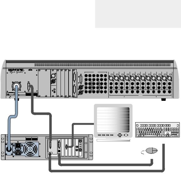
First, connect the Remote CPU to the console.
1.Connect the DC power cable between the Remote CPU and the console. Rotate the outer sleeve of the connector clockwise until the sleeve is snug and finger-tight.
Caution: The Remote CPU weighs 42 pounds, so we recommend that if you mount it in a rack, you place it at the bottom of the rack and provide additional support at the rear of the unit.
|
|
|
A |
B |
C |
D |
|
TAPE 1-8 |
TAPE 9-16 |
TAPE 17-24 |
|
|
|
|
|
|
|
|
|
|
|
|
|
|
|
|
|
|
|
|
56 INPUT 72 CHANNEL |
|
|
DIGITAL I/O 1 |
|
|
|
ANALOG I/O |
|
|
LINE INPUTS |
|
|
12 |
11 |
10 |
9 |
8 |
7 |
6 |
5 |
4 |
3 |
2 |
1 |
||
|
|
DIGITAL MIXER |
|
|
AES/EBU |
|
|
|
& |
|
|
(BAL/UNBAL) |
|
|
||||||||||||||
|
|
|
|
|
|
|
BUS OUT 1-8 |
|
|
|
|
|
|
|
|
|
|
|
|
|
|
|
|
|||||
|
|
|
|
|
|
|
|
|
|
SURROUND OUT |
18 |
17 |
16 |
15 |
14 |
13 |
+48V |
+48V |
+48V |
+48V |
+48V |
+48V |
+48V |
+48V |
+48V |
+48V |
+48V |
+48V |
|
|
|
|
|
|
|
|
|
|
|
|
|
|
|
|
|
PH |
PH |
PH |
PH |
PH |
PH |
PH |
PH |
PH |
PH |
PH |
PH |
|
|
|
|
|
|
|
|
|
|
OUT |
|
|
|
|
|
|
MIC |
MIC |
MIC |
MIC |
MIC |
MIC |
MIC |
MIC |
MIC |
MIC |
MIC |
MIC |
|
WARNING: |
|
|
|
|
|
|
|
|
|
|
|
|
|
|
|
|
|
|
|
|
|
|
|
|
|
|
|
|
|
|
|
|
|
|
|
|
ANALOG |
|
|
|
|
|
|
|
|
|
|
|
|
|
|
|
|
|
|
|
SHUT OFF REMOTE POWER SUPPLY BEFORE CONNECTING |
|
|
|
IN |
|
|
|
24 |
23 |
22 |
21 |
20 |
19 |
|
|
|
|
|
|
|
|
|
|
|
|
|||
OR DISCONNECTING POWER SUPPLY CABLE FROM CONSOLE |
|
|
|
|
|
|
|
|
|
|
|
|
|
|
|
|
|
|
|
|
|
|
|
|
|
|||
|
POWER |
CONSOLE |
|
|
|
|
|
|
|
|
|
|
|
|
|
|
|
|
|
|
|
|
|
|
|
|
|
|
|
SUPPLY |
DATA |
|
|
|
|
|
|
|
|
|
|
|
|
|
|
|
|
|
|
|
|
|
|
|
|
|
|
|
|
|
|
|
|
|
|
|
|
|
MASTER OUT |
2 TRACK IN A |
PHONES 1 |
PHONES 2 |
LINE IN |
LINE IN |
LINE IN |
LINE IN |
LINE IN |
LINE IN |
LINE IN |
LINE IN |
LINE IN |
LINE IN |
LINE IN |
LINE IN |
||
|
|
|
|
|
|
|
|
|
|
|
L |
R |
L |
R |
|
|
|
|
|
|
|
|
|
|
|
|
|
|
|
|
|
|
|
|
OUT |
|
|
|
|
|
|
|
|
|
|
|
|
|
|
|
|
|
|
|
|
|
|
|
|
|
|
|
|
|
|
|
|
|
CR |
2 TRACK IN B |
STUDIO OUT |
INSERT |
INSERT |
INSERT |
INSERT |
INSERT |
INSERT |
INSERT |
INSERT |
INSERT |
INSERT |
INSERT |
INSERT |
|||
|
|
|
|
|
|
DIGITAL I/O 2 |
|
|
|
|
MAIN |
|||||||||||||||||
|
|
|
|
|
|
|
|
|
L |
L |
R |
L |
R |
L |
R |
|
|
|
|
|
|
|
|
|
|
|
|
|
|
|
|
|
|
|
S/PDIF |
|
|
|
|
|
|
|
|
|
|
|
|
|
|
|
|
|
|
|
|
|
|
|
|
|
|
|
|
|
|
|
|
IN |
|
|
|
|
|
|
|
|
|
|
|
|
|
|
|
|
|
|
|
|
|
|
|
|
|
|
|
|
ANALOG |
NEAR FIELD |
2 TRACK IN C |
PUNCH I/O |
TALKBACK |
|
|
|
|
|
|
|
|
|
|
|
|
||
|
|
|
|
|
|
IN |
|
|
|
|
CR |
|
|
|
|
|
|
|
|
|
|
|
|
|
|
|
|
|
|
|
|
|
|
|
|
|
|
|
|
L |
R |
L |
R |
|
|
|
|
|
|
|
|
|
|
|
|
|
|
CAUTION |
WARNING: |
SERIAL NUMBER |
MANUFACTURING DATE |
|
|
OUT |
|
|
|
R |
|
|
|
|
|
|
|
|
|
|
|
|
|
|
|
|
|
|
|
AVIS: |
É |
|
|
|
|
|
|
|
|
|
|
|
|
|
|
AUX |
AUX |
AUX |
AUX |
AUX |
AUX |
AUX |
AUX |
AUX |
AUX |
AUX |
AUX |
REPLACE WITH THE SAME TYPE FUSE AND RATING. |
UTILISE UN FUSIBLE DE RECHANGE DE MÊME TYPE. |
|
|
|
|
|
|
|
|
|
|
|
|
|
|
12 |
11 |
10 |
9 |
8 |
7 |
6 |
5 |
4 |
3 |
2 |
1 |
|
DISCONNECT SUPPLY CORD BEFORE CHANGING FUSE |
DEBRANCHER AVANT DE REMPLACER LE FUSIBLE |
|
|
|
|
|
|
|
|
|
|
|
|
|
|
|
|
|
|
|
|
AUX OUT |
|
|
|
|
|
|
|
|
|
|
|
|
|
|
|
|
MASTER OUT |
|
|
|
|
|
|
|
|
|
|
|
|
(BAL/UNBAL) |
|
|
|
|
|
WARNING: SHUT OFF POWER TO UNIT BEFORE INSTALLING OR REMOVING CARDS! |
|
DIGITAL EFFECTS CARDS |
DIGITAL I/O |
SYNC |
ALT I/O |
TAPE IN/OUTS |
|
|
|
|
|
|
|
|
|
|
|
|
|
|
|
|
|
|
PATENTS PENDING |
|||
|
|
|
|
|
|
|
|
|
|
|
|
|
|
|
|
|
|
|
|
|
|
|
||||||
Data Cable
DC Power
Cable
MACKIE DESIGNS |
SERIAL NUMBER |
MANUFACTURING DATE |
THIS DEVICE COMPLIES WITH PART 15 OF THE FCC RULES. OPERATION IS SUBJECT TO |
|
|
THE FOLLOWING TWO CONDITIONS: 1) THIS DEVICE MAY NOT CAUSE HARMFUL |
|
|
INTERFERENCE AND 2) THIS DEVICE MUST ACCEPT ANY INTERFERENCE RECEIVED THAT |
|
PARALLEL |
MAY CAUSE UNDESIRED OPERATION |
|
|
|
|
DATA |
120V |
|
CONSOLE |
60Hz, 2.8A |
|
|
|
|
MOUSE |
|
|
KEYBOARD |
120/230V |
|
|
1.0/0.5A |
|
|
PC-Compatible Keyboard
Multi-Sync Video Monitor
PS/2 Mouse
D8B Manual • Chapter 1 • page 4
CPU
CONSOLE DATA
KEYBOARD
Keyboard
PARALLEL |
MIDI |
|
Ethernet
MOUSE |
Mouse |
Video |
|
|
 CONCEIVED, DESIGNED, AND MANUFACTURED BY MACKIE DESIGNS INC • WOODINVILLE • WA • USA • MADE IN USA • FABRIQUE AU USA • COPYRIGHT ©1997 •
  THE FOLLOWING ARE TRADEMARKS OR REGISTERED TRADEMARKS OF MACKIE DESIGN INC.: "MACKIE", "DIGITAL SYSTEMS", D8B AND THE "RUNNING MAN" FIGURE •
2.Connect the data cable between the Remote CPU and the console. Rotate the thumbscrews on each connector clockwise until they are finger tight.
3.Make sure the POWER switch on the Remote CPU is off.
4.Connect the detachable linecord to the Remote CPU. Shortly, we’ll connect to AC power.
Next, connect the keyboard, mouse, and video monitor.
These connections are optional, but we strongly recommend using them to get the most from your new Digital 8•Bus console.
PARALLEL
CONSOLE DATA
MOUSE
KEYBOARD
 CONCEIVED, DESIGNED, AND MANUFACTURED BY MACKIE DESIGNS INC • WOODINVILLE • WA • USA • MADE IN USA • FABRIQUE AU USA • COPYRIGHT ©1997 •
  THE FOLLOWING ARE TRADEMARKS OR REGISTERED TRADEMARKS OF MACKIE DESIGN INC.: "MACKIE", "DIGITAL SYSTEMS", D8B AND THE "RUNNING MAN" FIGURE •
D8B Manual • Chapter 1 • page 5
1.Plug a PC-compatible keyboard into the KEYBOARD port on the back of the Remote CPU.
2.Plug a PS/2 compatible mouse into the MOUSE port on the back of the Remote CPU.
3.Plug an SVGA video monitor into the VIDEO port on the back of the Remote CPU.
Note: We highly recommend the use of a multisync monitor; however, if one is unavailable you must use a monitor capable of at least a 72Hz scan rate. We recommend using a 17-inch or larger monitor for best results.
Now connect the audio inputs and outputs to the console.
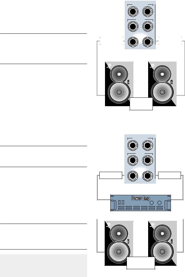
1.Connect the CR NEAR FIELD or CR MAIN outputs on the back of the Digital 8•Bus to the line inputs of the power amplifier. These outputs are wired balanced when using a tip-ring-sleeve connector or unbalanced when using a tip-sleeve connector. Use instrument/line-level cable for this connection.
2.Connect monitor speakers to the output of the power amplifier using speaker cable. Always use high quality wire. The sound you hear will be more reliable and accurate.
Note: If you’re using powered monitors, connect the Left and Right CR NEAR FIELD outputs directly to the line inputs on the powered monitors.
Optional Refreshments
Have a sip of java and a biscotti.
Details
Make sure the POWER switch on the Remote CPU is off. Now plug the linecord into an AC outlet properly configured for your model. Leave the POWER switch off while connecting the peripheral equipment to the console.
Note: The Remote CPU should be treated as you would any computer. We recommend that you use a UPS (Uninterruptible Power Supply) and a surge protector on the AC line.
Caution: Never connect or disconnect anything except microphone or line-level inputs while the console is powered up.
MASTER OUT
L R
CR
MAIN
L R
CR
 NEAR FIELD
Line Cable |
L |
R |
Line Cable |
|
|
Powered |
Monitors |
Connect directly from CR NEARFIELD or CR MAIN to powered reference monitors using line-level cable.
MASTER OUT
L R
CR
MAIN
L R
CR
 NEAR FIELD
L |
R |
Line Cable |
Line Cable |
|
|
|
|
|
|
|
|
|
|
|
|
|
|
|
|
|
|
|
Speaker Cable |
|
Speaker Cable |
||
|
|
|
|
|
|
Non-powered |
Monitors |
Connect from D8B outputs to power amp using line cable, then from amp to non-powered speakers using speaker cable.
D8B Manual • Chapter 1 • page 6
Turn on the power switch on the front panel of the Remote CPU, then turn on the power to all your peripheral equipment. The Digital 8•Bus takes a few moments to load the Mackie Real Time OS (Operating System) and initialize the DSPs. When the Vacuum Fluorescent Display (VFD) in the onboard Fat Channel Section indicates EQ settings for channel 1, the console is ready to use.
Fast Track Power-Up
1.Switch D8B power on.
2.Verify that SPEAKER LEVEL V-Pot is turned all the way down.
3. Switch on all peripherals |
FAST |
(processors, recorders, |
TRACK |
|
|
interfaces, etc.). |
|
4.Switch on monitor amplifier or powered monitors.
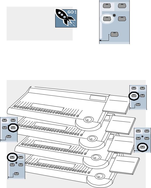
These buttons let you access four completely different sets of controls, referred to as Fader Banks. A fifth fader bank, HUI mode, is available by pressing SHIFT+MASTERS. Even though only one Fader Bank is accessible at a time, all are fully functional at all times. Use of a computer monitor provides onscreen control of two fader banks at a time.
MASTERS |
SHIFT |
1-24 |
25-48 |
MIC/LINE |
TAPE IN |
(TRACK) |
(MONITOR) |
49-72
EFFECTS
BANK SELECT
A New Way of Thinking:
Four Consoles in One!
With the Digital 8•Bus, what you get is way more than what you see at first glance. Directly above the Master L/R fader, locate four buttons labeled MIC/LINE, TAPE IN, EFFECTS, and MASTERS.
Now that you’ve got the Digital 8•Bus powered up, try the different fader banks.
•Press the MIC/LINE button and set up a random set of fader levels.
•Press the TAPE IN button and set up a completely different set of fader levels.
•Do the same for EFFECTS and MASTER.
|
|
|
C |
|
|
|
|
|
|
|
|
|
|
|
|
hannels |
|
|
|
|
|
|
|||
|
|
|
|
|
|
1- |
|
|
|
|
|
|
|
|
|
|
|
|
|
24 |
|
|
|
||
MASTERS |
SHIFT |
|
|
|
|
|
|
|
|
|
|
|
1-24 |
25-48 |
|
C |
ha |
nnels |
2 |
5- |
|
|
|
||
|
|
|
|
|
|
|
|
|
||||
|
|
|
|
|
|
|
|
|
|
|
|
|
|
|
|
|
|
|
|
|
|
48 |
|
|
|
MIC/LINE |
TAPE IN |
|
|
|
|
|
|
|
|
|
|
|
(TRACK) |
(MONITOR) |
|
|
|
|
|
|
|
|
|
|
|
|
49-72 |
|
|
|
|
|
|
|
|
|
|
|
EFFECTS |
|
|
|
|
|
|
|
|
|
|
|
|
BANK SELECT |
|
FX Retu |
|
|
|
|
|
|
|
|
||
|
|
|
|
|
|
|
|
|
|
|
||
|
|
|
|
rn 1-16; |
|
|
|
|
||||
|
|
|
|
|
|
|
|
ALT Re |
|
|
||
|
|
|
|
|
|
|
|
|
|
turn 1-8 |
|
|
|
MASTERS |
SHIFT |
Grou |
|
|
|
|
|
|
|
||
|
1-24 |
25-48 |
|
8;MIDI |
|
|
|
|||||
|
|
|
|
ps 1- |
|
|
1- |
|
|
|||
|
|
|
|
|
|
|
|
|
|
8;Bus |
|
|
|
MIC/LINE |
TAPE IN |
|
|
|
|
|
|
|
|
1- |
|
|
|
|
|
|
|
|
|
|
|
8 |
||
|
(TRACK) |
(MONITOR) |
|
|
|
|
|
|
|
|
|
|
|
49-72 |
|
|
|
|
|
|
|
|
|
|
|
|
EFFECTS |
|
|
|
|
|
|
|
|
|
|
|
|
BANK SELECT |
|
|
|
|
|
|
|
|
|
|
|
|
|
|
|
MASTERS |
SHIFT |
|
|
|
|
|
1-24 |
25-48 |
|
Fader |
Bank 1 |
MIC/LINE |
TAPE IN |
|
||
(TRACK) |
(MONITOR) |
|
||||
|
|
|
|
|||
Channels 1-24 |
|
|
49-72 |
|
||
Mic/Line |
|
|
EFFECTS |
|
||
Tracking |
|
|
BANK SELECT |
|
||
Fader Bank |
2 |
|
|
|||
Channels |
25-48 |
|
|
|||
Monitor/Tape |
In |
|
|
|
||
Mixdown |
|
|
|
|
|
|
|
|
|
|
MASTERS |
SHIFT |
|
Fader Bank 3 |
|
||
Channels |
|
|
|
FX |
49-72 |
|
|
Return 1-16 |
|
|
|
ALT |
|
|
|
Return 1-8 |
|
|
|
Fader |
|
4 |
|
|
Bank |
||
Virtual |
1-8 |
||
MIDI |
Groups |
||
Controllers 1-8 |
|||
Bus |
|
|
|
1-8 Masters |
|
|
|
1-24 |
25-48 |
MIC/LINE |
TAPE IN |
(TRACK) |
(MONITOR) |
49-72
EFFECTS
BANK SELECT
D8B Manual • Chapter 1 • page 7

As you switch back and forth between all four fader banks, the faders will move to their respective settings for each bank. You’ll find that this becomes your most popular demonstration. Your friends will love it; your spouse will love it; your pet will be mildly amused.
This exercise demonstrates a process that will become second nature as you increase your skills on the Digital 8•Bus. The layered approach to digital mixing is actually very convenient, while at the same time providing tons of features in a compact package. This mixer contains more flexibility and features than most consoles taking up 12 or more feet of desk space and costing up to 50 times more!
Fader Bank Selection
•MIC/LINE button = Fader Bank 1 (Channels 1–24)
•TAPE IN button = Fader Bank 2 (Channels 25–48)
•EFFECTS button = Fader Bank 3 (Channels 49– 72: Internal Effects Returns, FX 1–16, and ALT RETurns 1–8)
•MASTERS button = Fader Bank 4 (Virtual Groups 1–8, MIDI Controllers 1–8, Bus Masters 1–8)
•SHIFT+MASTERS button = Fader Bank 5 (with HUI Mode active)
This architecture provides a total of 56 inputs,
with Fader Banks 1 and 2 providing 48 inputs, and the 8 ALT Returns in Fader Bank 3 providing another 8 inputs.
One of the primary applications the Digital 8•Bus was designed for is multitrack recording (generally up to 24 tracks). This involves tracking and monitoring, bouncing, overdubbing, and mixdown. You can think of Fader Bank 1 and Fader Bank 2 as two separate mixing consoles, where Fader Bank 1 is used for tracking and Fader Bank 2 is used for monitoring and mixdown.
Two 24-track machines can easily be connected to the D8B for mixdown: one into the Fader Bank 1 line inputs, and the other into the Fader Bank 2 (Tape) I/O cards. This setup provides an amazing amount of control through automation, routing, and DSP!
Note: Although the D8B is perfectly set up for 24-track recording, it’s possible to route channels to 46 outputs, all at the same time: 24 direct outputs (3 cards), 8 buses (Alt I/O), 2 main stereo outputs, and 12 auxes.
Let’s Get Some Sound Happening
• Mixer Power On.
• Monitors connected and on.
• Microphone or Instrument plugged into Channel One.
FAST
• Phantom Power button TRACK pushed in if required.
•Fader Bank 1 (MIC/LINE selected).
•Press the MIC button down when using a microphone; leave it up for an instrument.
•While sound source is active, adjust TRIM for a reading around –15 on the channel 1 meter.
•Select L–R in the ASSIGNMENT section, then verify that the ASSIGN button on Channel One lights up green.
•In the CONTROL ROOM section, select MASTER L–R.
•Select the desired SPEAKERS in the CONTROL ROOM section.
•Set the SPEAKER LEVEL V-pot to about 11:00.
•Turn the MASTER L/R fader up to unity.
•Slowly raise the level of the Channel One fader until you hear sound.
•The Master L/R meters should display levels.
•Rejoice in the sense of accomplishment while listening to crystal-clear audio.
Refer to Figure 1-1 for the Fast Track Graphic description of this procedure.
Details
1.Especially for digital connections, it’s important that the Digital 8•Bus is powered up first. This procedure helps establish the mixer as a primary source in the digital sync scheme.
2.Be sure you’ve noted which output is connected to the monitor system(s) and be sure they’re powered up.
3.Be sure the microphone or instrument is plugged into Channel 1 and that Fader Bank 1 (MIC/LINE) is selected. It doesn’t take long to get used to selecting the fader bank you really need to access; however, at first make a conscious effort to include this step in your routine.
4.Be sure the button below the gain trim labeled MIC is pressed down for a microphone or is in the up position for an instrument When working fast this button is sometimes overlooked. If it’s in the wrong position there won’t be any signal to play with. That’s bad. Get in the habit of following the signal from the source to the destination—step by step. If you don’t leave any steps out you’ll be successful every time.
D8B Manual • Chapter 1 • page 8
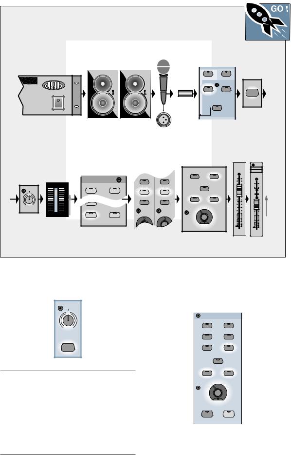
Figure 1-1 Completing the Microphone Signal Path
Follow this graphic map to quickly complete a signal path using a microphone to capture the
FAST
sound source.. T
RACK
|
Mic into |
|
|
Speakers On and |
Mic Input |
Select Fader |
|
|
Bank 1 |
||
Connected to Mixer |
|
||
|
|
|
|
Power On |
Phantom |
|
|
|
MASTERS |
SHIFT |
|
|
power |
1-24 |
25-48 |
|
|
MIC/LINE |
TAPE IN |
|
|
(TRACK) |
(MONITOR) |
|
|
|
49-72 |
|
|
EFFECTS |
|
|
|
BANK SELECT |
|
Mic Button
Down
MIC |
Trim Up Until
Channel Meter Reads
Around –15 dBFS
|
|
1 |
|
TRIM |
OL |
||
2 |
|||
LINE |
4 |
||
MIC |
7 |
||
|
|
10 |
|
|
|
15 |
|
|
|
20 |
|
0 |
60 |
25 |
|
30 |
|||
-20dB |
+40dB |
||
1 |
40 |
||
60 |
|||
|
|
50 |
|
25
Select L/R in ASSIGNMENT, then Verify Assign on Channel Strip
ASSIGNMENT |
REC/RDY |
REC/RDY |
|
|
|
||
ASSIGN |
ASSIGN |
ASSIGN |
ASSIGN |
|
|
||
|
BUS 2 |
|
|
ASSIGN |
|
WRITE |
WRITE |
|
|
|
|
BUS 7 |
BUS 8 |
|
|
ASSIGN |
ASSIGN |
|
|
L-R |
ROUTE TO |
|
|
|
TAPE |
|
|
Verify |
Master Fader |
||||
|
at Unity |
||||
MASTER L/R |
|
||||
|
MASTER |
||||
|
|
|
|
L/R |
GROUP 1 |
|
|
|
|
|
FX 1 |
|
|
|
|
|
1 |
|
|
|
dB |
|
25 |
|
|
|
10 |
|
|
2 TRACK C |
MASTER |
|
|
|
dB |
|
L-R |
|
5 |
|
10 |
|
|
|
|
|
|
|
|
|
|
|
5 |
|
|
|
U |
|
|
MONO |
|
|
|
|
U |
OR |
|
|
5 |
|
|
|
|
10 |
|
5 |
|
NEAR FIELD |
MAIN |
|
|
|
10 |
SPEAKERS |
|
|
20 |
|
|
|
|
|
|
|
20 |
|
|
|
30 |
|
|
|
|
|
|
|
30 |
|
|
|
40 |
|
|
|
|
|
50 |
|
40 |
|
|
|
|
|
|
|
|
|
60 |
|
50 |
|
|
|
|
60 |
|
SPEAKER LEVEL |
|
|
|
||
|
|
|
|
||
Select Monitors/Set |
|
|
Raise Channel |
||
V-pot Around 11:00 |
|
|
|||
|
|
Level to Hear |
|||
|
|
|
|
|
|
5.Start with gain TRIM down. While talking into the mic or playing the instrument, turn it up until the level stays around –15 to –10 on the channel one meter.
TRIM
LINE |
|
MIC |
|
0 |
60 |
-20dB |
+40dB |
1
MIC
Note: The TRIM and MIC button status are two of the only controls that are not written into automation or snapshot data. That’s a disadvantage of analog circuitry, but these controls are necessary. Running a strip of white safe-release tape across the top label strip allows for careful recording of each channel’s TRIM level and MIC button status. This kind of tape can be removed and folded for storage with session documentation, guaranteeing accurate settings whenever you need to restore the mix.
6.In the CONTROL ROOM section, press the MASTER L–R button so the yellow light comes on. Assigning this button sends whatever is coming from the MASTER L/R fader to the selected speakers.
CONTROL ROOM
2 TRACK A |
DIGITAL IN 1 |
2 TRACK B |
DIGITAL IN 2 |
2 TRACK C |
MASTER |
|
L-R |
|
MONO |
|
OR |
NEAR FIELD |
MAIN |
SPEAKERS
SPEAKER LEVEL
DIM |
TALKBACK |
D8B Manual • Chapter 1 • page 9
7.In the ASSIGNMENT section, verify that when L–R is selected (green light on) the ASSIGN button in Channel One lights up green. This is basic bus assignment procedure. Anything you want to come out the MASTER L–R bus must light up on the assign button of each desired channel. In similar fashion, any channel that needs to be assigned to Bus 1 must have the channel assign button lit when Bus 1 is selected in the ASSIGNMENT section.
ASSIGNMENT
ASSIGN |
ASSIGN |
BUS 1 |
BUS 2 |
ASSIGN |
ASSIGN |
BUS 3 |
BUS 4 |
ASSIGN |
ASSIGN |
BUS 5 |
BUS 6 |
ASSIGN |
ASSIGN |
BUS 7 |
BUS 8 |
ASSIGN |
ASSIGN |
L-R |
ROUTE TO |
|
TAPE |
8.Be sure the SPEAKER button is lit that corresponds to your monitor system connection—that the yellow light shows on NEAR FIELD or MAIN.
9.Turn the SPEAKER LEVEL V-pot up to about 11:00.
10.Turn the MASTER L/R fader up to unity.
11.Slowly raise the level of the Channel One fader until you hear sound.
TRIM |
TRIM |
LINE |
|
12 |
|
REC/RDY |
REC/RDY |
ASSIGN |
ASSIGN |
WRITE |
WRITE |
|
|
ASSIGNMENT |
||
10 |
10 |
|
|
|
20 |
20 |
ASSIGN |
ASSIGN |
|
|
|
|||
|
|
|
BUS 2 |
|
30 |
30 |
|
|
|
|
|
ASSIGN |
|
|
40 |
40 |
BUS 7 |
BUS 8 |
|
50 |
50 |
|||
|
|
|||
60 |
60 |
|
|
|
|
|
ASSIGN |
ASSIGN |
|
|
|
L-R |
ROUTE TO |
|
|
|
|
TAPE |
|
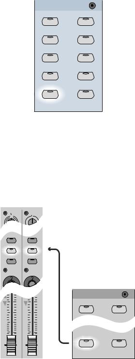
Signal Routing Concept
The Digital 8•Bus, with its multilayer technology, literally performs the work of at least four consoles. To help organize the various connections, visualize each bank as a new console. The “V” or “Multi-V” diagrams that follow provide a simple and accurate mental image of the signal flow and/or processing while you put the Digital 8•Bus through its paces.
Figure 1-2 demonstrates a simple connection scheme utilizing a microphone that’s routed though the D8B to the monitor system.
Figure 1-3 demonstrates a tracking setup. Notice how the graphic representation of two separate fader banks supports the mental image of the D8B concept: sound source into the MIC/LINE bank, then routed to the multitrack, then back into the TAPE IN bank. Figure 1-4 adds a mixdown recorder. The beauty
of this concept lies in its flexibility. Start at the beginning, middle, or end of the signal path—it doesn’t matter. When the routing concept is understood, the process is simple.
D8B Manual • Chapter 1 • page 10
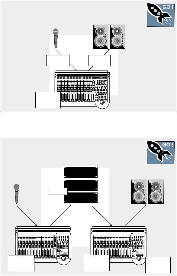
Figure 1-2 Simple Microphone Connection/Basic Live Setup
This setup illustrates the most fundamental use of the D8B. A very basic live setting might require only this limited level of complexity.
FAST
TRACK
Channel 1–24
Mic/Line In
Monitor Outs
to Speakers
Channels 1–24 |
Tracking Mixer |
Fader Bank 1 |
Figure 1-3 Setting Up to Track
The graphic below highlights the simplicity of the D8B tracking procedure. Once levels to tape are set, using the Channel Trim controls, it’s typically best to monitor the mix from the TAPE IN Fader Bank throughout tracking.
Multitrack
FAST
TRACK
|
|
|
|
|
|
|
|
|
|
|
|
|
|
|
|
|
|
|
|
|
|
|
|
|
|
|
|
|
|
|
|
From Tape to Channel |
|
|
|
|
|
|
|
|
|
|
|
|
|
Monitor Outs |
|||||||||||||||||
Channel 1–24 |
|
|
|
|
|
|
|
|
|
|
|
|
|
|
|
|
|
|
|
|
|
|
|
|
|
|
|
|
|
|
|
||||||||||||||||||||||||||||||||
Mic/Line In |
|
|
|
|
|
|
Tape or Bus Outs to |
|
|
25–48 Inputs |
|
|
|
|
|
|
|
|
to Speakers |
||||||||||||||||||||||||||||||||||||||||||||
|
|
|
|
|
|
|
|
|
|
|
|
|
|
|
|
|
|
|
|
|
|
Multitrack Inputs |
|
|
|
|
|
|
|
|
|
|
|
|
|
|
|
|
|
|
|
|
|
|
|
|
|
|
|
|
|
|
|
|
|
||||||||
|
|
|
|
|
|
|
|
|
|
|
|
|
|
|
|
|
|
|
|
|
|
|
|
|
|
|
|
|
|
|
|
|
|
|
|
|
|
|
|
|
|
|
|
|
|
|
|
|
|
|
|
|
|
|
|||||||||
|
|
|
|
|
|
|
|
|
|
|
|
|
|
|
|
|
|
|
|
|
|
|
|
|
|
|
|
|
|
|
|
|
|
|
|
|
|
|
|
|
|
|
|
|
|
|
|
|
|
|
|
|
|
|
|
|
|
|
|
|
|
|
|
|
|
|
|
|
|
|
|
|
|
|
|
|
|
|
|
|
|
|
|
|
|
|
|
|
|
|
|
|
|
|
|
|
|
|
|
|
|
|
|
|
|
|
|
|
|
|
|
|
|
|
|
|
|
|
|
|
|
|
|
|
|
|
|
|
|
|
|
|
|
|
|
|
|
|
|
|
|
|
|
|
|
|
|
|
|
|
|
|
|
|
|
|
|
|
|
|
|
|
|
|
|
|
|
|
|
|
|
|
|
|
|
|
|
|
|
|
|
|
|
|
|
|
|
|
|
|
|
|
|
|
|
|
|
|
|
|
|
|
|
|
|
|
|
|
|
|
|
|
|
|
|
|
|
|
|
|
|
|
|
|
|
|
|
|
|
|
|
|
|
|
|
|
|
|
|
|
|
|
|
|
|
|
|
|
|
|
|
|
|
|
|
|
|
|
|
|
|
|
|
|
|
|
|
|
|
|
|
|
|
|
|
|
|
|
|
|
|
|
|
|
|
|
|
|
|
|
|
|
|
|
|
|
|
|
|
|
|
|
|
|
|
|
|
|
|
|
|
|
|
|
|
|
|
|
|
|
|
|
|
|
|
|
|
|
|
|
|
|
|
|
|
|
|
|
|
|
|
|
|
|
|
|
|
|
|
|
|
|
|
|
|
|
|
|
|
|
|
|
|
|
|
|
|
|
|
|
|
|
|
|
|
|
|
|
|
|
|
|
|
|
|
|
|
|
|
|
|
|
|
|
|
|
|
|
|
|
|
|
|
|
|
|
|
|
|
|
|
|
|
|
|
|
|
|
|
|
|
|
|
|
|
|
|
|
|
|
|
|
|
|
|
|
|
|
|
|
|
|
|
|
|
|
|
|
|
|
|
|
|
|
|
|
|
|
|
|
|
|
|
|
|
|
|
|
|
|
|
|
|
|
|
|
|
|
|
|
|
|
|
|
|
|
|
|
|
|
|
|
|
|
|
|
|
|
|
|
|
|
|
|
|
|
|
|
|
|
|
|
|
|
|
|
|
|
|
|
|
|
|
|
|
|
|
|
|
|
|
|
|
|
|
|
|
|
|
|
|
|
|
|
|
|
|
|
|
|
|
|
|
|
|
|
|
|
|
|
|
|
|
|
|
|
|
|
|
|
|
|
|
|
|
|
|
|
|
|
|
|
|
|
|
|
|
|
|
|
|
|
|
|
|
|
|
|
|
|
|
|
|
|
|
|
|
|
|
|
|
|
|
|
|
|
|
|
|
|
|
|
|
|
|
|
|
|
|
|
|
|
|
|
|
|
|
|
|
|
|
|
|
|
|
|
|
|
|
|
|
|
|
|
|
|
|
|
|
|
|
|
|
|
|
|
|
|
|
|
|
|
|
|
|
|
|
|
|
|
|
|
|
|
|
|
|
|
|
|
|
|
|
|
|
|
|
|
|
|
|
|
|
|
|
|
|
|
|
|
|
|
|
|
|
|
|
|
|
|
|
|
|
|
|
|
|
|
|
|
|
|
|
|
|
|
|
|
|
|
|
|
|
|
|
|
|
|
|
|
|
|
|
|
|
|
|
|
|
|
|
|
|
|
|
|
|
|
|
|
|
|
|
|
|
|
|
|
|
|
|
|
|
|
|
|
|
|
|
|
|
|
|
|
|
|
|
|
|
|
|
|
|
|
|
|
|
|
|
|
|
|
|
|
|
|
|
|
|
|
|
|
|
|
|
|
|
|
|
|
|
Channels 1–24 |
Channels 25–48 |
Channel Assign- |
|
Tracking Mixer |
Tape Returns |
||
ments Routed to |
|||
Fader Bank 1 |
Fader Bank 2 |
||
L/R Mix |
|||
|
|
D8B Manual • Chapter 1 • page 11
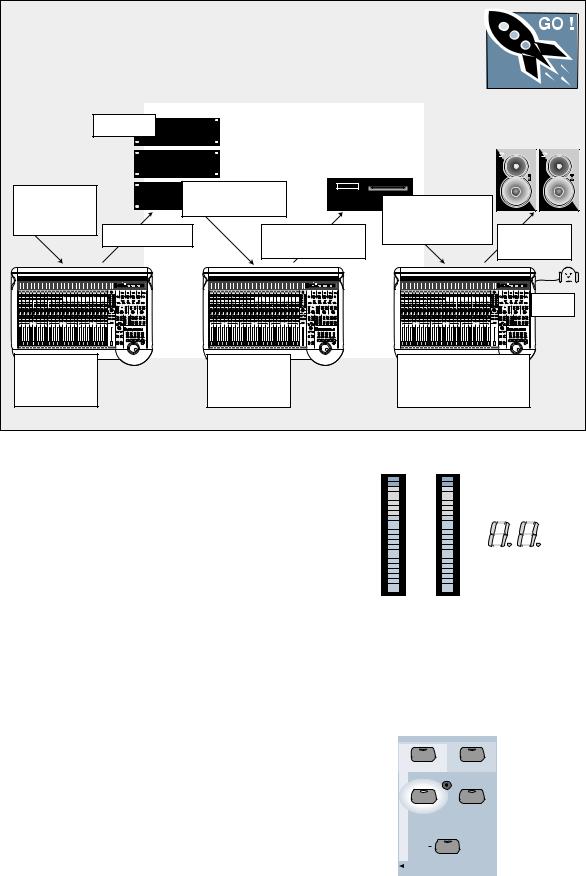
Figure 1-4 Basic Mixdown Setup
This is a basic mixdown setup. Live Mic/Line input source might be used for any audio source: live vocals, instruments, or effects returns.
FAST
TRACK
Multitrack
Outboard Effects, |
From Tape to Channel |
From Mix Playback to |
|
||
|
25–48 Inputs |
|
|||
MIDI Gear, Live |
|
|
|||
|
|
2-Track Input (Analog |
|
||
Room Mics, etc. |
|
From Master Out to |
Monitor Outs |
||
Tape or Bus Outs |
or Digital) |
||||
|
|||||
|
|
Mixdown Recorder |
|
to Speakers |
|
Channels 1–24
Tracking Mixer
Fader Bank 1
Channels 25–48
Monitor Tape
Fader Bank 2
Phones |
Monitor Mixdown Machine
at CONTROL ROOM in the
Master Section
Use this diagram for troubleshooting!
Signal Flow |
|
|
|
|
OL |
|
|
|
CHANNEL |
|
||||
|
|
|
|
|
|
|
||||||||
|
|
|
|
2 |
|
|
|
|
|
|
|
|
||
The previous diagrams help create an accurate |
|
|
|
|
4 |
|
|
|
|
|
|
|
|
|
|
|
|
|
7 |
|
|
|
|
33 |
|
|
|||
mental image of how the D8B functions. The signal |
|
|
|
|
10 |
|
|
|
|
|
|
|||
flow diagram in Figure 1-5 (on the next page) looks |
|
|
|
|
15 |
|
|
|
|
|
|
|||
|
|
|
|
20 |
|
|
|
|
|
|
||||
more closely at the actual path the signal takes from |
|
|
|
|
30 |
|
|
|
|
|
|
|||
|
|
|
|
|
25 |
|
|
|
|
|
|
|
|
|
a point of origin to a chosen destination. This is a |
|
|
|
|
35 |
|
|
|
|
|
|
|
|
|
simplified flow-diagram designed to provide a “bird’s- |
|
|
|
|
40 |
|
|
|
|
|
|
|
|
|
|
|
|
|
50 |
|
|
|
|
|
|
|
|
||
eye” view. Follow the signal from left to right. Notice |
|
|
|
|
|
|
|
|
|
|
|
|
||
|
|
|
|
|
|
|
|
|
|
|
|
|
||
|
LEFT |
RIGHT |
|
|||||||||||
the first thing the signal encounters, after the analog |
|
|
||||||||||||
|
|
|
|
|
|
|
|
|
|
|
|
|
||
inputs (including the analog trim), is the analog-to- |
2. Be sure you verify the Bank Selection whenever |
|||||||||||||
digital converter. The audio remains in the digital |
||||||||||||||
|
you need to make a change. At first it’s easy to |
|||||||||||||
domain from that point until it finally converts back |
|
|||||||||||||
|
forget to check the Fader Bank status. However, |
|||||||||||||
to analog at the main outputs, bus outputs, and |
|
|||||||||||||
|
once you’ve adjusted to the layered consoles, |
|||||||||||||
external aux sends. Simply follow the arrows to |
|
|||||||||||||
|
maneuvering throughout the entire console will |
|||||||||||||
discover the path—you never know where you might |
|
|||||||||||||
|
become second nature. |
|
|
|
|
|
|
|||||||
end up. For a more detailed block diagram of the |
|
|
|
|
|
|
|
|||||||
|
|
|
|
|
|
|
|
|
|
|
|
|
||
D8B signal path refer to Figure 1-6. |
|
|
|
|
|
|
|
|
|
|
|
|
|
|
Keep Close Track of These Concepts |
|
|
|
MASTERS |
SHIFT |
|
|
|
||||||
|
|
|
|
|
|
|||||||||
|
|
|
|
|
1-24 |
|
25-48 |
|
|
|
|
|
||
1. The Channel Select Display, next to the Master |
|
|
|
|
MIC/LINE |
TAPE IN |
|
|
|
|||||
L/R meters, always displays the currently |
|
|
|
|
|
|
||||||||
|
|
|
|
(TRACK) |
(MONITOR) |
|
|
|
||||||
selected channel number no matter which Fader |
|
|
|
|
49-72 |
|
|
|
|
|
|
|||
Bank is selected. If an adjustment is required in |
|
|
|
|
|
|
|
|
|
|
|
|
|
|
|
|
|
|
|
|
|
|
|
|
|
|
|
||
the Fat Channel, verify that the channel you |
|
|
|
|
|
EFFECTS |
|
|
|
|||||
|
|
|
|
|
|
|
|
|||||||
intend to adjust is displayed here. |
|
|
|
|
|
BANK SELECT |
|
|
||||||
|
|
|
|
|
|
|
|
|||||||
|
|
|
|
|
|
|
|
|
|
|
|
|
||
|
|
|
|
|
|
|
|
|
|
|
|
|
||
D8B Manual • Chapter 1 • page 12
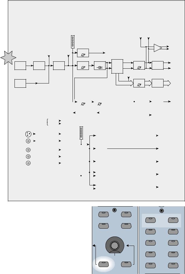
Figure 1-5 Signal-Flow Diagram
Simply begin at the far left star and follow the route the signal must take to reach the master output. DSP includes all dynamics, equalization, and phase controls.
|
|
Main Inserts |
|
Tracking/Routing |
Channel |
R |
L |
Meter |
|
|
|
|
|
|
|
|
|
|
|
AES/EBU Out |
|
|
Pre-DSP |
Post-DSP |
Level to |
|
|
|
|
S/PDIF Out |
|
|
Tape |
|
To Tape Outputs |
|
|
|
|||
|
Insert |
Insert |
|
|
|
|
|
||
|
|
|
Channel |
Channel |
|
L |
|
|
|
Analog |
Analog to |
DSP |
|
Master L/R |
Digital to |
Main |
|||
Fader |
Pan |
Bus |
|||||||
Inputs |
Digital |
(EQ, Comp, |
Fader |
Analog |
|||||
CH 1-24 |
Converter |
Gate, etc.) |
|
|
Assign |
R |
Converter |
Out |
|
|
|
|
|
|
|
|
|
||
|
|
|
Pre |
|
|
Bus |
|
|
|
|
|
|
|
|
Inserts |
|
|
||
|
|
|
|
|
|
|
|
||
Optional |
|
|
|
Post |
|
Bus Master |
Digital to |
Bus 1-8 |
|
|
|
|
|
|
|||||
Tape |
|
|
|
|
|
|
Analog |
Outputs |
|
I/O Card |
|
|
|
|
|
Bus 1-8 |
Converter |
|
|
|
|
|
|
|
|
|
|
|
|
|
|
|
|
|
|
|
|
|
|
Aux Send |
|
|
Master Aux |
|
|
|
|
Digital to |
|
Aux |
|||||
|
|
|
|
|
|
|
|
|
|
|
|
|
|
|
|
|
|
|
|||||||||
|
|
|
|
|
|
|
|
|
|
|
|
Level |
|
|
Send Level |
|
|
|
|
Analog |
|
||||||
|
|
|
|
|
|
|
|
|
|
|
|
|
|
|
|
|
|
|
|
|
|
|
|
Converter |
|
Sends |
|
|
|
|
|
|
|
|
To FX Returns (Ch. 49-64), |
|
|
|
|
|
|
|
|
From Aux Sends 1 – 8, |
|
|
|
|
|
||||||
|
|
|
|
|
|
|
|
Internal |
|
|
|
L or R Main Insert, Channel |
|
|
|
|
|
||||||||||
|
|
|
|
|
|
|
L or R Main Inserts, |
|
|
|
|
|
|
|
|
|
|
|
|
||||||||
|
|
|
|
|
|
|
|
|
|
FX |
|
|
|
Pre or Post-DSP Insert, |
|
Lake Sammamish |
|
||||||||||
|
|
|
|
|
|
|
Channel Pre or Post-DSP Inserts, |
|
|
|
|
|
|
|
|||||||||||||
Monitoring |
|
|
|
|
|
or Bus 1-8 |
|
|
|
|
|
|
|
|
Plugin Chain, or Bus 1-8 |
|
6 miles |
|
|||||||||
|
|
From |
|
|
|
|
|
|
|
|
|
|
|
|
|||||||||||||
|
|
|
|
|
|
|
|
|
|
|
|
|
|
|
|
|
|
|
|
|
|
|
|
|
|||
|
|
|
|
L/R Out |
|
|
|
|
|
|
|
|
|
|
|
|
|
|
|
|
|
|
|
|
|
||
|
|
|
|
|
|
|
|
|
|
|
|
|
Main L/R |
|
|
|
|
|
|
|
|
||||||
|
|
|
|
|
|
|
|
|
|
|
|
|
Meter |
|
|
|
|
|
|
|
|
||||||
AES/EBU |
|
|
DAC |
|
|
|
|
|
|
|
|
|
|
|
|
|
Near Field |
|
|
|
|
|
|
CR |
|
||
|
|
|
|
|
|
|
|
|
|
|
|
|
|
|
|
|
|
|
|
|
|
||||||
|
|
|
|
|
|
|
|
|
|
|
|
|
|
|
Speaker |
|
|
|
|
|
|
|
|||||
|
|
|
|
|
|
|
|
|
|
|
|
|
|
|
|
|
|
|
|
|
|
|
|
Nearfield |
|
||
|
|
|
|
|
|
|
|
|
|
|
|
|
|
|
|
|
|
|
Level |
|
|
|
|
|
|
||
S/PDIF |
|
|
DAC |
|
|
|
|
|
|
|
|
|
|
|
|
|
|
|
|
|
|
Out |
|
||||
|
|
|
|
|
Control |
|
|
|
|
|
|
|
|
|
|
|
|
|
|
|
|
|
|
||||
|
|
|
|
|
|
|
|
|
|
|
|
|
|
|
|
|
|
|
|
|
|
|
|||||
|
|
|
|
|
|
|
|
|
Room |
|
|
|
|
|
|
|
|
|
|
|
|
|
|
|
|
||
|
|
|
|
|
|
|
|
|
|
|
|
|
|
|
|
|
|
|
|
|
|
|
|
|
|
|
|
|
|
|
|
|
|
|
|
|
Select |
|
|
|
|
|
|
|
Main |
|
|
|
|
|
CR |
|
|||
2 TRK A |
|
|
|
|
|
|
|
|
|
|
|
|
|
|
|
|
|
|
Speaker |
|
|
|
|
|
Main |
|
|
|
|
|
|
|
|
|
|
|
|
|
|
|
|
|
|
|
|
|
Level |
|
|
|
|
|
Out |
|
|
2 TRK B |
|
|
|
|
|
|
|
|
|
|
|
|
|
|
|
|
|
|
|
|
|
|
|
|
Studio |
|
|
|
|
|
|
|
|
|
|
|
|
|
|
|
|
|
|
|
|
|
|
|
|
|
|
|
|||
|
|
|
|
|
|
|
|
|
|
|
|
|
|
|
|
|
|
|
Studio |
|
|
|
|
|
|
||
2 TRK C |
|
|
|
|
|
|
|
|
|
|
|
|
|
|
|
|
|
|
Level |
|
|
|
|
|
Out |
|
|
|
|
|
|
|
|
|
|
|
|
|
|
|
|
|
|
|
|
|
|
|
|
|
|
||||
|
|
|
|
|
|
|
|
|
|
|
|
|
|
|
|
|
|
|
|
|
|
|
|
|
Phones 1 |
|
|
|
|
|
|
|
|
|
|
|
|
|
|
|
|
|
|
|
|
|
|
|
|
|
|
|
|
||
|
|
Auxes 9/10 |
|
|
|
|
|
|
|
|
|
|
|
|
|
|
Cue Mix 1 |
|
|
|
|
|
|
||||
|
|
|
|
|
|
|
|
|
|
|
|
|
|
|
Level |
|
|
|
|
|
Out |
|
|||||
|
|
Auxes 11/12 |
|
|
|
|
|
|
|
|
|
|
|
|
|
|
|
|
|
|
|
|
|||||
|
|
|
|
|
|
|
|
|
|
|
|
|
|
|
|
|
|
|
|
|
|
|
|
|
Phones 2 |
|
|
|
|
|
|
|
|
|
|
|
|
|
|
|
|
|
|
|
|
|
Cue Mix 2 |
|
|
|
|
|
|
||
|
|
|
|
|
|
|
|
|
|
|
|
|
|
|
|
|
|
|
Level |
|
|
|
|
|
Out |
|
|
|
|
|
|
|
|
|
|
|
|
|
|
|
|
|
|
|
|
|
|
|
|
|
|
|
|||
|
|
|
|
|
|
|
|
|
|
|
|
|
|
|
|
|
|
|
|
|
|
|
|
|
|
|
|
3.When using the V-Pot to adjust a parameter, make sure it’s assigned to make the change you need. Since the V-Pot is a multifunction control, it’s easy to assume it’s doing the job you want when it might be changing a completely different setting. Intentionally check the status of the V-Pot before making a change.
|
1-24 |
1-48 |
AUX 9-10 |
AUX 11-12 |
|
|
LEVEL TO TAPE |
DIGITAL TRIM |
PAN |
PAN |
|
|
AUX 1 |
AUX 2 |
AUX 3 AUX 4
|
MASTER |
AUX 5 |
AUX 6 |
|
|
||
PAN |
SOLO |
AUX 7 |
AUX 8 |
|
|
D8B Manual • Chapter 1 • page 13
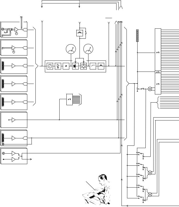
|
|
|
|
|
PRE-DSP |
KEY INPUT |
||
|
|
|
|
|
INSERT |
Default: Itself (the channel) |
|
|
ANALOG STEREO |
|
CHANNEL TAP |
|
OR: |
||||
|
BUS TAP |
CHANNEL TAP |
||||||
INSERT/RETURN |
|
AUX TAP |
ALT RETURNS |
|||||
|
|
|
|
2-TRACK DIGITAL INPUT |
BUS TAP |
|||
|
|
|
|
|
PLUG-INS |
AUX TAP |
||
|
|
|
|
|
|
|
2-TRACK DIGITAL INPUT |
|
MIC/LINE 1 (through 12) |
|
|
|
|
|
|
|
|
MIC IN |
TRIM |
|
|
|
|
|
|
|
MIC/LINE |
|
|
|
|
|
|
|
|
|
|
|
|
|
|
|
|
|
|
A to D |
|
|
|
|
|
|
|
48V |
|
|
|
|
EQ TO |
|
KEY EQ |
|
LINE IN |
|
|
|
DYNAMICS |
|
IN |
|
|
LINE 13 (through 24) |
|
|
GATE IN |
COMPRESSOR OUT |
|
|||
|
|
|
METER |
|
METER |
|
||
|
TRIM |
|
|
|
|
|
||
LINE IN |
|
|
|
|
|
|
|
|
A to D |
|
|
|
|
|
|
|
|
|
|
|
|
|
|
|
|
|
FROM TAPE 25 (through 32) |
|
|
|
|
|
|
|
|
|
A to D |
|
|
|
|
|
|
|
Analog 8 channel TAPE CARD |
DELAY |
DIG. TRIM |
PHASE |
GATE |
COMP |
HI PASS |
EQ |
|
|
(optional) |
|
|
|
|
|
|
|
FROM TAPE 33 (through 40) |
A to D |
Analog 8 channel TAPE CARD |
(optional) |
FROM TAPE 41 (through 48) |
TO |
|
|
|
BUS 1-8 |
A to D |
L/R MAIN INSERTS |
CH PRE/POST DSP INSERTS |
|
Analog 8 channel TAPE CARD |
|
(optional) |
|
FX card A. inputs 49–52 |
|
Inputs 53–64 (optional — B, C, D cards)
ALT I/O CARD 65-72 (optional) |
A to D |
TDIF/ADAT 8 channel format |
(optional) |
AES/EBU & S/PDIF STEREO INPUT
TO CONTROL ROOM
SELECT
“Mackie Digital 8•Bus Block Diagram 2 / 28 / 2003”
POST-DSP |
CHANNELTAP |
RETURNSALT |
TRACK-2 DIGITAL |
TAP/AUXBUS TAP |
|
|
INSERT |
|
|
|
|
|
|
PLUG-INS |
|
|
|
|
|
|
ONLY |
|
|
|
|
|
|
|
|
|
|
METER |
|
|
|
|
|
|
|
DIRECT ASSIGN |
|
|
|
|
|
|
TO TAPE OUT |
|
|
|
|
|
|
|
PFL SOLO |
|
|
|
|
|
MUTE |
PAN |
|
|
|
|
|
|
|
|
|
|
|
FADER |
|
|
|
|
|
|
PRE/ |
|
|
|
|
|
|
POST |
AUX 1–8 |
|
|
|
|
|
|
||
|
|
|
|
|
AUX |
|
|
|
|
|
|
LEVEL |
|
|
|
|
|
|
|
AUX |
|
|
|
|
|
AUX |
PAN |
|
|
|
|
|
|
|
|
|
|
|
|
LEVEL |
|
|
|
|
|
|
AUX |
|
|
|
|
|
|
LEVEL |
|
|
|
|
|
|
|
AUX |
|
|
|
|
|
|
PAN |
|
|
|
|
|
AUX |
|
|
|
|
|
|
LEVEL |
|
Figure 1-6 D8B Block Diagram
This diagram provides a detailed view of the D8B signal path.
D8B Manual • Chapter 1 • page 14

TAPE1–8 TAPE9–16 TAPE17–24 PFLSOLO SOLOL SOLOR MAINLEFT MAINRIGHT |
BUSES1–8 AUXSEND1–8 AUXSEND9 AUXSEND10 |
AUXSEND11 |
|
|
MAIN INSERT R (L) |
|
|
|
|
MIXDOWN SOLO SENDS |
|
D8B OUTPUT SECTION |
|
||||||
|
X2 LEFT AND (RIGHT) |
|
|||||||
ONLY SOLOED CHANNELS |
|
|
|||||||
12SENDAUX |
|
|
|
|
|
|
|||
|
|
|
TO MAIN L/R BUS |
|
|
|
|
|
|
|
|
|
|
MASTER |
|
|
|
|
|
|
|
|
|
FADER |
|
|
|
|
|
|
|
|
MIXDOWN |
SOLO |
|
D / A |
|
|
|
|
|
|
PFL/AFL/MIXDOWN |
|
|
|
|
||
|
|
|
PFL |
|
|
|
|
|
|
|
|
|
AFL |
SOLO |
|
|
|
|
|
|
|
|
|
|
|
|
|
|
|
|
|
|
|
LEVEL |
|
D / A |
|
|
|
|
|
|
AUX SOLO 9 (10) |
|
|
|
|
||
|
|
|
|
|
|
|
|
||
|
|
|
AUX 9/10 MASTER |
|
|
|
|
|
|
|
|
|
|
|
|
D / A |
|
|
|
|
|
|
|
|
|
|
TO SOLO BUS |
|
|
|
|
|
|
|
|
|
PHONES SELECT |
PH 1 |
|
|
|
|
|
|
|
|
CTRL RM |
|
|
|
|
|
AUX SOLO 11 (12) |
|
D / A |
9/10 |
|
PH 1 LEVEL |
|
|
|
|
|
|
|
|
11/12 |
|
|
|
|
|
|
|
|
|
|
|
|
|
|
|
|
|
|
|
CTRL RM |
PH 2 |
|
|
|
|
AUX 11/12 MASTER |
|
|
9/10 |
|
PH 2 LEVEL |
|
|
|
|
|
|
|
|
|
||
|
|
|
|
|
|
D / A |
11/12 |
|
|
|
|
|
|
|
|
|
|
||
|
|
|
|
|
|
D / A |
|
|
|
|
|
|
|
|
|
|
TALKBACK |
|
|
|
|
|
TB LEVEL |
|
|
|
|
|
|
|
|
|
|
|
|
(R) |
|
|
|
|
|
|
FROM |
|
|
|
TALKBACK TO STUDIO |
|
|
|
|
|
D / A |
|
|
|
|
|
|
|
|
|
S/PDIF IN |
|
|
|
|
|
|
|
|
|
|
|
|
|
|
|
|
|
|
|
FROM |
D / A |
|
|
|
|
|
|
|
|
AES/EBU IN |
|
|
|
|
|
|
|
|
|
|
|
|
|
|
|
|
|
|
|
|
|
|
DIG IN 1 |
|
|
|
AUX 9/10 |
|
|
2 TRK IN |
|
|
DIG IN 2 |
|
|
|
|
|
|
|
MASTER L-R |
|
|
|
||
|
|
|
A |
|
|
|
LEVEL |
||
|
|
|
|
2 TRK A |
CONTROL ROOM |
|
|
||
|
|
|
|
|
SELECT |
|
|
|
|
|
|
|
B |
|
|
|
|
|
|
|
|
|
|
2 TRK B |
|
|
|
|
|
|
|
|
C |
|
2 TRK C |
|
METERS |
NEARFIELD |
DIM |
|
|
|
|
|
|
|
|
|
|
|
|
|
|
|
|
|
|
|
LEVEL |
AUX 11/12 |
|
|
|
|
D / A |
|
|
|
|
|
|
|
|
|
|
|
|
DIM |
|
|
|
|
|
|
|
SOLO |
MONO LEFT |
||
|
|
|
BUS |
BUS INSERTS |
CONTROL |
(R) |
|
|
|
|
|
|
|
|
|
|
|||
|
|
|
TAP |
|
|
|
|
||
|
|
|
|
|
|
|
MAIN |
|
|
|
|
|
|
|
|
|
|
|
|
|
|
|
|
|
|
SURROUND MONITOR |
|
|
LEVEL |
|
|
|
|
|
|
|
|
|
|
|
|
|
|
|
|
LEVELS (x8 + MASTER) |
|
|
|
|
|
|
BUS LEVEL |
MUTE |
|
|
D / A |
|
|
|
|
|
|
|
|
|
|
||
|
|
|
|
|
|
|
|
|
|
|
|
|
LEVEL TO TAPE |
|
|
ASSIGN |
|
|
|
|
|
|
|
|
|
|
|
|
|
LEVEL TO TAPE
LEVEL TO TAPE
|
AUX SOLO 1 (of 8) |
|
|
AUX 1 (of 8) |
|
|
MASTER |
|
|
LEVEL |
D / A |
TAPE 1–8 TAPE9–16 TAPE17–24 PFL SOLO SOLO L SOLO R MAINLEFT MAINRIGHT BUSES1–8 SENDAUX 1–8 AUXSEND 9 AUXSEND 10 AUXSEND 11 AUXSEND 12 |
|
|
BUS 1-8 |
FX CARDS |
|
|
AUX |
|
|
TAP |
|
|
FROM |
|
|
L/R MAIN INSERTS |
|
|
CH PRE/POST DSP INSERT |
|
|
PLUG-IN |
|
S/PDIF
DIGITAL OUT LEFT
(R)
AES / /EBU
DIGITAL OUT LEFT
(R)
MAIN OUT LEFT
(R)
MAIN OUT LEFT
(R)
AUX 9/10
PHNS 1 LEFT
PHNS 2 LEFT
AUX 11/12
STUDIO OUT LEFT
(R)
NEARFIELD SPKR LEFT
(R)
MAIN
SPKR LEFT
(R)
BUS 1–8
TAPE 1–8
TAPE 9–16
TAPE 17–24
ALT I/0
AUX 1 – AUX 8
D8B Manual • Chapter 1 • page 15
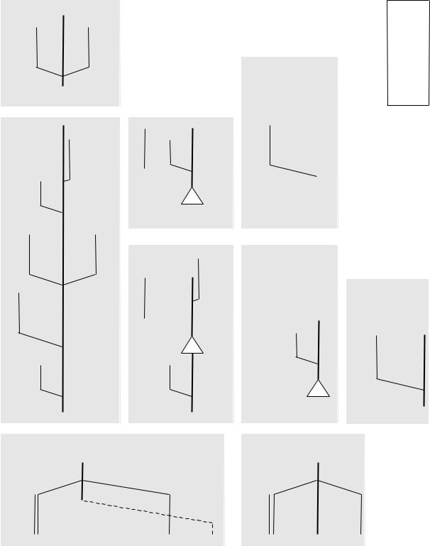
|
up+12dB |
|
dn–12dB |
|
EQ |
|
|
|
|
|
|
Effects |
gain |
0 |
gain |
|
|
|
|
|
|
|
|
Mackie |
|
|
|
|
|
|
|
|
|
|
|
|
levelup+10dB |
pancntr–3dB |
|
channelfader pan |
+22dBumaxout |
levelup+10dB |
0 0 0 |
|
|
||
|
|
Bus1-8 StudioOut Phones1&2 |
|
|
|||||||
|
|
|
|
|
|
|
|
||||
|
gainup+15dB |
|
|
|
gaindn–15dB |
compressor 4bandEQ |
|
|
st.auxpancntr-3dB |
|
|
levelup+20dB |
|
|
|
+22dBumaxout |
|
0 0 |
mix |
||||
fatDSP |
levelup+10dB |
0 |
|
|
|
digitaltrim |
Auxsend |
levelup+10dB |
0 0 |
|
chauxlevel |
|
dBloss |
0 |
|
|
|
|
dBgain |
|
|
dBgain |
|
|
20 |
|
|
|
|
|
|
40 |
|
|
60 |
linein 1-12 |
+22dBumaxinput |
+2dBumaxinput |
|
|
micin |
1-12 |
|
|
|
|
|
|
|
|
|
|
|
|
|||||
|
|
|
|
|
|
|
|||||
|
|
|
|
|
|
|
|||||
|
|
|
|
|
|
|
|||||
|
|
|
|
|
|
|
|||||
|
|
|
|
|
|
|
|||||
|
|
|
|
|
|
|
|||||
|
|
|
|
|
|
|
|||||
|
|
|
|
|
|
|
|||||
|
|
|
|
|
|
|
|||||
|
|
|
|
|
|
|
|||||
|
|
|
|
|
|
|
|||||
Figure 1-7 D8B Gain Structure Diagram
|
|
+22dBumaxout |
|
|
@Unitygain |
|
|
MackieDesigns Digital8•Bus |
GainStructureDiagram 5/15/01 |
|
|
|
|
|
|
|
MaxLevel |
|
|
|
|
Room |
|
|
|
|
0 |
|
|
|
|
|
|
|
|
|
|
|
|
|
|
||
Control |
|
|
|
|
|
|
|
|
|
|
XLR+28dBumaxout |
TRS+22dBumaxout |
|
|
|
|
A-C |
|
|
||
|
|
|
|
|
levelup+10 |
0 0 0 |
|
Inputs25-48,Returns1-8,2Trk |
+22dBumaxinput |
|
|
|
|
|
|
|
|
||||
MainL-R |
|
|
|
|
0 |
|||||
|
|
|
|
|
|
|||||
|
|
|
|
|
|
|
|
|||
|
|
|
|
dBloss |
|
0 |
|
dBgain |
|
|
in13-24 |
dBumaxinput |
20 |
|
|
20 |
|
|
|||
line |
+22 |
|
|
|
|
|
|
|
|
|
D8B Manual • Chapter 1 • page 16

Specifications
Meters:
•LED ladders displaying 24 channels, 24 LEDs per channel from –50 to 0 dBFS (0 dBFS = +20 dBu)
Frequency Response:
• 20 Hz – 20 kHz ±0.5 dB
Crosstalk (@ 1kHz)
• |
Adjacent channels: |
–90 dBu |
• Aux sends feed through: |
–90 dBu |
|
• |
Main outputs: |
–90 dBu |
Equalizer
• |
Gain Range: |
±15 dB |
• |
Frequency range: |
20 Hz – 20 kHz |
|
|
split into 4 bands |
• |
Q: |
1/12 to 3 octave |
Compressor
• |
Threshold: |
–60.0 to –1.0 dB |
• |
Attack: |
0.1 ms to 2.5 sec |
• |
Release: |
10.0 ms to 2.5 sec |
• |
Ratio: |
1.0:1 to inf:1 |
• |
Output: |
0.0 dB to 20.0 dB |
Gate
• |
Threshold: |
–60.0 to –1.0 dB |
• |
Attack: |
0.1 ms to 2.5 sec |
• |
Release: |
10.0 ms to 2.5 sec |
•Range (Expand off): 0 dB to 100 dB
•Ratio (Expand on): 1:1.0 to 1:inf
Digital Specs
•Converters:
24-bit, 115 dB Signal-to-Noise-Ratio (EIAJ), 106 dB Dynamic Range, 128X oversampling
•DSP:
32 bit (>190 dB dynamic range)
•CPU:
300 MHz Celeron
(166 MHz Pentium in earlier versions)
•Minimum System Requirements for v5.1: 32 MB RAM
166 MHz Pentium D8B CPU
•Recommended System Requirements for v5.1: 64 MB RAM
300 MHz Celeron D8B CPU
File Storage:
•Floppy drive, internal hard drive or 10-base-T Ethernet network
Dither:
• Apogee UV22 16-bit Super CD Encoding onboard
Analog Input/Output Section
•Output Level (0 dBu = 0.775V RMS)
•Left and Right Outputs: +22 dBu balanced 1/4" TRS +28 dBu balanced XLR
•Bus (Tape) out:
+22 dBu balanced 1/4" TRS
•Aux sends:
+22 dBu balanced 1/4" TRS
•Inserts:
+22 dBu unbalanced 1/4" TRS
Channel Section (mic/line)
•Line input: balanced 1/4" TRS input
•Mic Input: balanced XLR input
•Preamp dynamic range:
|
|
114 dB max. |
• |
E.I.N.: |
–129.5 dBu, 150 ohm source |
|
|
–131.2 dBV, 150 ohm source |
• |
CMRR: |
–83 dBu @1kHz |
• |
Distortion: |
0.005% @ 1kHz |
|
|
+14 dBu output level |
|
|
(20 Hz – 20 kHz filter) |
• |
Mic gain range: |
Unity to +60 dB |
• Line In gain range: |
–20 dB to +40 dB |
|
|
|
(channels 1-12) |
|
|
–20 dB to +20 dB |
|
|
(channels 13-24) |
• |
Input max. level: |
+4 dBu nominal |
|
|
+22 dBu clipping |
•Aux send gain range: off to +10 dB
•Bus out gain range: off to +10 dB
• Threshold: |
–60 to –1 dB |
• Ch. fader gain range: –100 to +10 dB
Physical Dimensions
•Console:
8.7" x 37.6" x 27.1" (221mm x 955mm x 688mm)
•Remote CPU:
5.25" x 19.0” x 20.0" (133mm x 483mm x 508mm)
Weight
• |
Console: |
73 lbs. (33.1kg) |
• |
Remote CPU: |
50 lbs. (22.7kg) |
Note: All specifications subject to change without notice.
D8B Manual • Chapter 1 • page 17
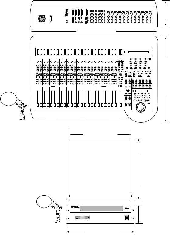
Physical Dimensions
D8B
CONSOLE SHIPPING WEIGHT 73 lbs. (33.1 kg)
D8B CPU SHIPPING WEIGHT 50 lbs. (22.7 kg)
8.7" |
(221mm) |
37.6" (955mm)
27.1" (688mm)
17.25" (43.8cm)
20" (50.8cm)
CPU |
5.25" (13.3cm) |
3U |
19.00" (48.3cm)
D8B Manual • Chapter 1 • page 18
Updating Software
Software upgrades can easily be downloaded from the Mackie website at www.mackie.com. Find the D8B section and select “Downloads.”
Always read the Release notes that accompany the software downloads. They contain valuable information specific to the current software revisions and install procedures.
Windows-based Computers
Follow these steps if you are downloading onto a Windows®-based computer:
1.Download the .ZIP files d8b5xxxx_PC.zip for the operating system installation, and the D8B Plug-in Demo Kit (ServicePack2.zip) for the plug-ins installation.
2.We recommend that you update the operating system first. Double-click on the d8b5xxxx_PC.zip file. This will launch the WinZip™ selfextraction utility.
3.The default "Unzip To" directory is set to C:\. If you prefer to have the files extracted to a different location, type the path into the provided text box and then press the Unzip button. Quit the WinZip™ self-extraction utility.
4.Locate the three extracted files, labeled d8b5xxxx Install 1.exe, d8b5xxxx Install 2.exe, and d8b5xxxx Install 3.exe, on your hard drive.
5.Double-click on the first file, d8b5xxxx Install 1.exe, and you'll see a "WinImage™ Self Extractor" dialog box.
6.Ensure that the "Writing On Floppy" check box is selected, then click the "OK" button in the upper right corner of the dialog box.
7.When the "Batch Assistant" dialog box appears, insert a double-sided, high-density 1.44MB floppy disk into drive A:\ and then click the "OK" button.
8.When the Winimage™ utility has completed writing to the first disk, be sure to label your disks so you know which is #1, #2, #3.
Additionally, be sure not to leave a disk in your floppy drive. Rebooting your PC with the disk in the drive can create problems with your PC.
Repeat steps 5 through 7 for the second and third disk image files.
9.With the D8B console power supply turned off, insert installation disk #1 into the floppy disk drive.
10.Power on the console power supply.
11.Follow the instructions on the D8B control surface. (Note: The installer no longer uses the VGA screen; typical boot is about 30 seconds.)
12.Place the 2nd floppy disk in the drive when prompted by the installation software.
13.Remove the 2nd floppy disk when prompted and insert the 3rd floppy disk.
14.Remove the 3rd floppy disk when prompted and power down the console power supply, then power back on.
15.You now have the updated D8B operating system installed.
16.Make sure you read the release notes. They have important info about this upgrade.
Note: Repeat the above procedure with the ServicePack2.zip file to install the plug-in update. After updating the plug-ins software on the D8B, you must perform the “Erase UFX Memory” and “Upgrade UFX Cards” procedures (under Windows in the upper menu bar) to upgrade the UFX cards that are installed in the D8B (see page 86).
Macintosh Computers
Follow these steps if you are downloading onto a Mac OS® computer:
1.Download the self-extracting file d8b5xxxx_Mac.hqx for the operating system installation, and the D8B Plug-in Demo Kit (Plugin Service Pack2.sea) for the plug-ins installation.
2.We recommend that you update the operating system first. Double-click on the d8b5xxxx_Mac.hqx file to extract the three disk images.
3.Launch Apple's DiskCopy utility (you may need to download the DiskCopy utility from http:// www.apple.com or check the system installations disks that came with your system).
4.Depending on your version of DiskCopy, either click the "Load Image File..." button or choose "Make a Floppy" from the Utilities menu.
5.Locate the image file labeled d8b5xxxx Install 1.img that was extracted onto your hard drive.
6.DiskCopy will prompt you (depending on your version of DiskCopy) to insert a floppy disk into the floppy disk drive. With older versions of Disk Copy, you may need to click the "Make a copy" button first.
7.Once the disk has been ejected from the computer, be sure to label your disk so you know which is #1, #2, and #3. Then follow steps 4 through 6 to create the second and third installation disks from the second and third disk image files (d8b5xxxx Install 2.img; d8b5xxxx Install 3.img).
8.With the D8B console power supply turned off, insert installation disk #1 into the floppy disk drive.
9.Power on the console power supply.
10.Follow the instructions on the D8B control surface. (Note: The installer no longer uses the VGA screen; typical boot is about 30 seconds.)
D8B Manual • Chapter 1 • page 19

11.Place the 2nd floppy disk in the drive when prompted by the installation software.
12.Remove the 2nd floppy disk when prompted and place the 3rd floppy disk in the drive.
13.Remove the 3rd floppy disk when prompted and
power down the console power supply, then power back on.
13.You now have the updated D8B operating system installed.
14.Make sure you read the release notes. They
have important info about this upgrade.
Note: Repeat the above procedure with the Plugin Service Pack2.sea file to install the plug-in update. After updating the plug-ins software on the D8B, you must perform the “Erase UFX Memory” and “Upgrade UFX Cards” procedures (under Windows in the upper menu bar) to upgrade the UFX cards that are installed in the D8B.
Note to Macintosh USB Floppy drive users:
Apple's Disk Copy program will not work using the above method with a USB floppy drive because the menu option "Make a Floppy..." will not be available. You must use Aladdin Systems' ShrinkWrap program available for purchase and trial download from http://www.aladdinsys.com/ shrinkwrap/index.html. Once you have ShrinkWrap installed, substitute these steps for steps 3-6 in the above directions.
3.Launch ShrinkWrap.
4.Select "Write Image back to Disk..." from the Image menu (command-B).
5.Locate the image file labeled d8b5xxxx Install 1.img that was extracted onto your hard drive.
6.ShrinkWrap will prompt you to insert a floppy disk into the floppy disk drive.
Summary
This chapter has been specifically designed to help you understand the basic concept of the Digital 8•Bus architecture. The following two chapters describe the physical surface controls and the software features and capabilities. The last chapter describes specific applications as they pertain to unique recording tasks and needs.
Chapters 2 and 3 support what you’ll encounter in Chapter 4. Feel free to jump ahead, but keep in mind that you’ll probably need to use these second two chapters as a reference for the terms and controls that are new to you.
D8B Manual • Chapter 1 • page 20
Where Is It?
Chapter 2
D8B Manual • Chapter 2 • page 21
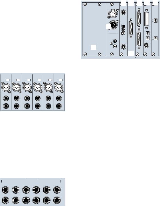
It’s Time to Locate Everything…
No matter how fast you want—or need—to get started, take advantage of this simple map of the territory: it provides the Fast Track overview of the D8B. It’s amazing how artistically supportive this console is. It’s well worth your time to take a look at all the controls so you can put them to work efficiently.
Rear Panel Description
This section describes rear panel connector types, their functions, and associated signal buses.
Channels 1–12 Inputs
6 |
5 |
4 |
3 |
2 |
1 |
+48V |
+48V |
+48V |
+48V |
+48V |
+48V |
PH |
PH |
PH |
PH |
PH |
PH |
MIC |
MIC |
MIC |
MIC |
MIC |
MIC |
LINE IN |
LINE IN |
LINE IN |
LINE IN |
LINE IN |
LINE IN |
INSERT |
INSERT |
INSERT |
INSERT |
INSERT |
INSERT |
Each channel contains:
•XLR mic input. Be sure the MIC button is pressed down on the control surface channel strip.
•Phantom power On/Off button depending on mic requirements.
•1/4" TRS line input—balanced or unbalanced. Be sure the MIC switch is in the up position on the control surface channel strip.
•1/4" TRS channel insert/direct output jack.
Channels 13–24 Inputs
LINE INPUTS
(BAL/UNBAL)
18 |
17 |
16 |
15 |
14 |
13 |
24 |
23 |
22 |
21 |
20 |
19 |
Channels 13 through 24 have 1/4" TRS (Tip/Ring/ Sleeve) line input connectors that accept balanced and unbalanced signals.
Card Cage Section
A |
B |
C |
D |
|
6 4 |
1 2 3 |
|||
|
|
|
|
DIGITAL I/O 1 |
|||||
|
|
|
|
APOGEE |
PDI•8 |
ANALOG I/O |
|
|
|
|
|
|
|
AES/EBU |
|
|
|
||
|
|
|
|
CLOCK I/O |
|
|
|
|
|
|
|
|
|
|
|
|
|
|
|
|
|
|
|
IN |
WORD CLOCK OUT |
|
ANALOG OUT |
|
TDIF |
|
|
|
|
|
|
|
|||
|
|
|
|
7 |
|
|
I/O |
|
|
|
|
|
|
|
|
AES/EBU |
|
|
|
|
|
|
|
OUT |
|
|
|
|
|
|
|
|
|
|
|
|
|
|
|
|
|
|
|
DIGITAL I/O 2 |
|
|
ANALOG IN |
ADAT OPTICAL |
IN OUT |
|
|
|
|
S/PDIF |
|
|
|||
|
|
|
|
IN |
WORD CLOCK IN |
|
|||
|
|
|
|
|
|
||||
|
8 |
|
|
OUT |
|
|
|
|
SYNC |
|
|
|
|
|
|
|
|
||
|
|
|
|
|
|
|
|
|
|
|
|
|
|
|
|
5 |
|
|
OPT•8 |
|
|
|
|
|
|
|
|
|
|
|
DIGITAL EFFECTS CARDS |
DIGITAL I/O |
SYNC |
ALT I/O |
|
TAPE IN/OUTS |
|||
This is where you plug in the optional I/O cards of your choosing, to customize the Digital 8•Bus for your own application.
There are three slots assigned as TAPE IN/OUTS. Each slot provides I/O for 8 channels, so you can add up to 24 tape sends and returns, or additional inputs and outputs.
•TO TAPE (OUTPUT) – The D8B can route any channel in Fader Banks 1, 2 and 3 to the multitrack through these connectors. In addition, the bus outputs in Fader Bank 4 (MASTERS) can be routed out the tape outputs.
•FROM TAPE (INPUT) – Multitrack outputs are
fed back into channels 25–48 (Fader Bank 2) through these connectors. Depending on the specific I/O card, these inputs will receive any line-level analog or digital signal.
Each I/O card contains its own labeling protocol, but the fundamental concepts described above pertain to all.
1 Analog I/O (AIO•8)
•Each 25-pin D-sub connector handles 8 balanced analog channels.
•Top connectors send line-level outputs to the multitrack (or other line-level equipment).
•Bottom connectors receive line-level analog signal from the multitrack outputs (or other line-level equipment).
•Each card offers I/O for 8 channels.
•Connectors are compatible with TASCAM DA-88, 25-pin analog connectors.
2 Apogee Digital I/O (DIO•8)
•Two digital-format ins and outs: ADAT optical (fiber optic connections) and TASCAM TDIF (25-pin D-sub connections).
•Select one digital format at a time in the Setup screen.
•One BNC sync connector for master clock connection from the D8B to TASCAM clock recipient.
•Use the DIO•8 card as a format converter between either optical and/or TDIF.
D8B Manual • Chapter 2 • page 22
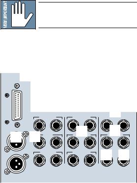
3 ADAT Optical (OPT•8)
•Two digital ADAT optical (fiber optic) connections.
•Each card offers I/O for 8 channels.
4 AES/EBU (PDI•8)
•One 25-pin D-sub connector in digital AES/EBU format.
•Each card offers I/O for 8 channels.
5 ALT I/O Card Slot
•Separate input/output card slot offering 8 more ins and outs.
•Holds any card: AIO•8, DIO•8, OPT•8, or PDI•8.
•Inputs show up at RETURNS faders (channels 65–72).
•Outputs are assignable to either the 8 bus outputs (BUS 1–8), the 12 Aux Sends (AUX 1–12), or the MASTER L-R outputs.
•Assignments are made in the Digital I/O menu.
6 The Clock I/O Card
•Provides word clock in and out to connect with other digital equipment.
•For use as a master or slave clock source.
•Supports 48kHz and 44.1kHz internal sample rates, with vari-speed capabilities.
•Supports external sample rates between 32kHz and 50kHz.
Note: The Apogee Clock I/O card replaces the standard clock card that is shipped in the SYNC slot with the D8B.
7 The Digital I/O Card (2-track)
•AES/EBU digital I/O. Stereo interconnect for master record machine. Input is connected to DIGITAL 1 in the CONTROL ROOM monitor section.
•S/PDIF digital I/O. Input is connected to DIGITAL 2 in the CONTROL ROOM monitor section.
•Same source output as MASTER L-R.
8 Digital Effects Card Slots
•Room for four separate effects cards.
•MFX – Mackie Effects card with two stereo processors.
•UFX – Universal DSP engine with functions dependent on specific plug-in effects. Each card is capable of four discrete mono, two stereo, or one stereo and two mono effects.
•L-R Mix, Channel Pre or Post Insert, Buses 1-8, and Plugin Chain, in addition to the Aux sends 1–12, internally route to the four card locations.
•Using the configurable plug-in architecture, insert plug-in capability is available for channels 1–48 (Preand Post-DSP), Buses 1-8, and Main Mix L-R.
•Effects return to the main L-R mix at Fader Bank 3 via FX 1–16.
Reminder: Power down the system before installing any cards!
Master Input/Output Section
BUS OUT& bl1-8
SURROUND OUT
bn
|
|
MASTER OUT |
2 TRACK IN A |
PHONES 1 |
PHONES 2 |
|
|
L R |
L R |
|
|
9 |
bm |
CR |
br |
bo |
|
L R |
L R |
L |
R |
||
|
|
MAIN |
2 TRACK IN B |
STUDIO OUT |
|
L |
|
|
|
|
|
|
|
CR |
L R |
bp |
bq |
|
|
L R |
|||
|
|
NEAR FIELD |
2 TRACK IN C |
PUNCH I/O |
TALKBACK |
R |
|
|
|
|
|
MASTER OUT
9 MASTER OUTputs (1/4" TRS and XLR)
•Fed from the Master L/R fader on the console surface.
•Both sets deliver balanced line-level signals. However, the TRS Master Outputs also provide unbalanced line-level signals.
•Post fader, DSP, and D/A converter.
bl BUS OUT 1–8 (SURROUND OUT)
•25-pin D-sub connector provides eight balanced line-level outputs.
•Any channel (1–48), internal effects return, or ALT IN can be assigned to one or more bus outputs.
•In Stereo Mode: Output level is controlled by the BUS 1–8 MASTERS (Fader Bank 4).
•In Surround Mode: Output level is controlled by the Surround Monitor Level controls in the Surround window.
D8B Manual • Chapter 2 • page 23
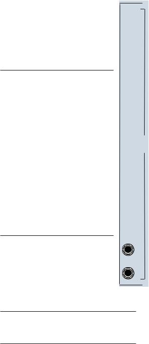
bm CR MAIN and CR NEAR FIELD
•Pairs of 1/4" TRS stereo line-level outputs for sending signals to control room speakers.
•Both outputs carry the same signal (as selected in the Control Room section).
•Levels can be adjusted independently or linked together.
•Post-DSP, Master L/R fader, and D/A converter.
•The signal fed to these outputs is selected in the CONTROL ROOM section of the control surface.
bn PHONES 1 and 2
•Each jack carries an unbalanced stereo signal through a 1/4" TRS jack.
•Designed to connect to virtually any stereo headphones. Phones 1 and 2 V-Pots adjust to compensate for headphones with exceptionally high or low impedances.
•The signal at these outputs is determined by the PHONES/CUE MIX 1 and PHONES/CUE MIX 2 source selection on the control surface.
•Aux 9–10, Aux 11–12, or the CONTROL ROOM selection can feed either or both Phones/Cue outputs.
•The Master L/R mix can be copied to either or both Aux 9–10 or 11–12 Cue Mixes.
bo STUDIO OUT L-R
•Signal at these outputs is determined by the CONTROL ROOM source selection.
•Balanced analog stereo-paired outputs for sending signals to the studio.
•1/4" TRS outputs can drive a balanced or unbalanced input.
•Level controlled by the V-Pot in the SOLO/STUDIO section of the control surface, when STUDIO LEVEL is selected.
bp PUNCH I/O
•A remote switch connection for activating the MMC master record function—to punch in or out of record.
•Use with a normally-open switch.
bq TALKBACK
•A remote switch connection for engaging the talkback function.
•Duplicates the Talkback switch in the CONTROL ROOM section.
•Use with a normally-open switch.
br 2 TRACK A, B, and C
•Balanced 1/4" TRS inputs for receiving linelevel analog signals from a 2-track recorder.
•The separate left/right pairs feed the 2 TRACK A, B, and C buses in the control room monitoring section.
•Can accept balanced and unbalanced signals.
AUX OUT Section
•There are 12 Aux sends available.
•Auxes 1–8 provide mono 1/4" TRS analog line-level outputs.
•Auxes 9 and 10 are linked together as a stereo pair of 1/4" TRS analog line-level outputs.
•Auxes 11 and 12 are linked together as a stereo pair of 1/4" TRS analog linelevel outputs.
Note: Auxes 1–12 simultaneously feed the analog Aux sends and the internal effects cards (by default).
Each MFX card handles two separate mono inputs, so auxes are paired. MFX effects returns are stereo, so each card, while receiving two discrete mono inputs, returns two sets of stereo outputs to the EFFECTS Bank. Internally, Aux 1 returns to FX 1/2; Aux 2 returns to FX 3/4; Aux 3 returns to FX 5/6; continuing through Aux 8, which returns at FX 15/16.
UFX cards handle 4 mono, two stereo, or one stereo and two mono inputs.
For each UFX card, no matter what the Aux input selection, returns appear at the FX faders numbered the same as their respective slots.
If all UFX effects are mono, each return correlates directly to the Slot number ( 9 to 9, 10 to 10, etc.)
 AUX AUX AUX AUX AUX AUX AUX AUX AUX AUX
1
2
3
4
5
6 OUTAUX
7
8
9
10
(BAL/UNBAL)
•When stereo effects are selected, regardless of the Aux input selection, returns appear at the FX faders numbered the same as their respective slots. For stereo effects with mono inputs, the effects return at the respective slot numbered pair (input 9 returns at FX 9/ 10; input 11 returns at FX 11/12, etc.)
AUX |
11 |
AUX |
12 |
Note: Patching from an Aux output does not interrupt the internal sends to the FX Cards, so it’s possible to run both internal and outboard effects at the same time.
D8B Manual • Chapter 2 • page 24
 Loading...