


Operation Guide
INPUT
 OL
OL 
8
0
4
8
 24
24 
0 = +4dBu
PHONES
1
OO
2
OO
|
INPUT SOURCE SELECT |
MIC |
|
|
|
||
DAW |
2-TRACK |
2-TRACK PHONO |
|
MIX |
A |
B |
|
STUDIO OUTS
OO
POWER
MONITOR SELECT
A B C
TALKBACK
MAX
PHONES/
STUDIO OUTS
SOURCE
MAX
INPUT SOURCE(S) |
OFF |
PHONES MIX INPUT |
ON |
MAX |
|
|
|
VOLUME |
|
|
|
|
MONO |
|
DIM |
|
|
OO |
MAX |
MUTE |
OO |
MAX |
|
LEVEL |
LEVEL |
||||
|
|||||
TO |
TO |
2-TRACKS |
PHONES/ |
|
STUDIO |
STUDIO COMMAND SYSTEM
BIG KNOB
Important Safety Instructions
1.Read these instuctions.
2.Keep these instructions.
3.Heed all warnings.
4.Follow all instructions.
5.Do not use this apparatus near water.
6.Clean only with dry cloth.
7.Do not block any ventilation openings. Install in accordance with the manufacturer’s instructions.
8.Do not install near any heat sources such as radiators, heat registers, stoves, or other apparatus (including amplifiers) that produce heat.
9.Do not defeat the safety purpose of the polarized or grounding-type plug. A polarized plug has two blades with one wider than the other. A grounding-type plug has two blades and a third grounding prong. The wide blade or the third prong are provided for your safety. If the provided plug does not fit into your outlet, consult an electrician for replacement of the obsolete outlet.
10.Protect the power cord from being walked on or pinched particularly at plugs, convenience receptacles, and the point where they exit from the apparatus.
11.Only use attachments/accessories specified by the manufacturer.
12.Use only with a cart, stand, tripod, bracket, or table specified by the manufacturer, or sold with the apparatus. When a cart is used, use caution when moving the cart/apparatus combination to avoid injury from tip-over.
PORTABLE CART WARNING
Carts and stands - The Component should be used only with a cart or stand that is recommended by the manufacturer.
A Component and cart combination should be moved with care. Quick stops, excessive force, and uneven surfaces may cause the Component and cart combination to overturn.
CAUTION |
AVIS |
RISK OF ELECTRIC SHOCK |
|
DO NOT OPEN |
|
RISQUE DE CHOC ELECTRIQUE |
|
NE PAS OUVRIR |
|
CAUTION: TO REDUCE THE RISK OF ELECTRIC SHOCK |
|
DO NOT REMOVE COVER (OR BACK) |
|
NO USER-SERVICEABLE PARTS INSIDE |
|
REFER SERVICING TO QUALIFIED PERSONNEL |
|
ATTENTION: POUR EVITER LES RISQUES DE CHOC |
|
ELECTRIQUE, NE PAS ENLEVER LE COUVERCLE. AUCUN |
|
ENTRETIEN DE PIECES INTERIEURES PAR L’USAGER. CONFIER |
|
L’ENTRETIEN AU PERSONNEL QUALIFIE. |
|
AVIS: POUR EVITER LES RISQUES D’INCENDIE OU |
|
D’ELECTROCUTION, N’EXPOSEZ PAS CET ARTICLE |
|
A LA PLUIE OU A L’HUMIDITE |
|
The lightning flash with arrowhead symbol within an equilateral triangle is intended to alert the user to the presence of uninsulated "dangerous voltage" within the product’s enclosure, that may be
of sufficient magnitude to constitute a risk of electric shock to persons.
Le symbole clair avec point de fl che l’int rieur d’un triangle quilat ral est utilis pour alerter l’utilisateur de la pr sence
l’int rieur du coffret de "voltage dangereux" non isol d’ampleur suffisante pour constituer un risque d’ l ctrocution.
The exclamation point within an equilateral triangle is intended to alert the user of the presence of important operating and maintenance (servicing) instructions in the literature accompanying the appliance.
Le point d’exclamation l’int rieur d’un triangle quilat ral est employ pour alerter les utilisateurs de la pr sence d’instructions importantes pour le fonctionnement et l’entretien (service) dans le livret d’instruction accompagnant l’appareil.
13.Unplug this apparatus during lightning storms or when unused for long periods of time.
14.Refer all servicing to qualified service personnel. Servicing is required when the apparatus has been damaged in any way, such as powersupply cord or plug is damaged, liquid has been spilled or objects have fallen into the apparatus, the apparatus has been exposed to rain or moisture, does not operate normally, or has been dropped.
15.This apparatus has been equipped with a rocker-style AC mains power switch. This switch is located on the rear panel and should remain readily accessible to the user.
16.This apparatus does not exceed the Class A/Class B (whichever is applicable) limits for radio noise emissions from digital apparatus as set out in the radio interference regulations of the Canadian Department of Communications.
ATTENTION — Le présent appareil numérique n’émet pas de bruits radioélectriques dépassant las limites applicables aux appareils numériques de class A/de class B (selon le cas) prescrites dans le réglement sur le brouillage radioélectrique édicté par les ministere des communications du Canada.
17.Exposure to extremely high noise levels may cause permanent hearing loss. Individuals vary considerably in susceptibility to noise-induced hearing loss, but nearly everyone will lose some hearing if exposed to sufficiently intense noise for a period of time. The U.S. Government’s Occupational Safety and Health Administration (OSHA) has specified the permissible noise level exposures shown in the following chart.
According to OSHA, any exposure in excess of these permissible limits could result in some hearing loss. To ensure against potentially dangerous exposure to high sound pressure levels, it is recommended that all persons exposed to equipment capable of producing high sound pressure levels use hearing protectors while the equipment is in operation. Ear plugs or protectors in the ear canals or over the ears must be worn when operating the equipment in order to prevent permanent hearing loss if exposure is in excess of the limits set forth here.
Duration Per Day |
Sound Level dBA, |
Typical |
In Hours |
Slow Response |
Example |
8 |
90 |
Duo in small club |
6 |
92 |
|
4 |
95 |
Subway Train |
3 |
97 |
|
2 |
100 |
Very loud classical music |
1.5102
1 |
105 |
Tami screaming at Adrian about deadlines |
0.5110
0.25 or less |
115 |
Loudest parts at a rock concert |
WARNING — To reduce the risk of fire or electric shock, do not expose this apparatus to rain or moisture.
2 |
BIG KNOB |
Table of Contents |
|
Introduction................................................................................................................ |
4 |
Getting Started.......................................................................................................... |
4 |
Zero the Controls ....................................................................................................................................... |
4 |
Connections................................................................................................................................................. |
4 |
Set the Levels .............................................................................................................................................. |
5 |
Hookup......................................................................................................................... |
6 |
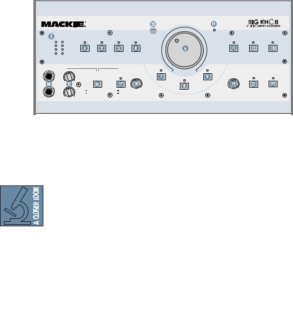
Big Knob Features ...................................................................................................... |
7 |
Front Panel................................................................................................................................................... |
7 |
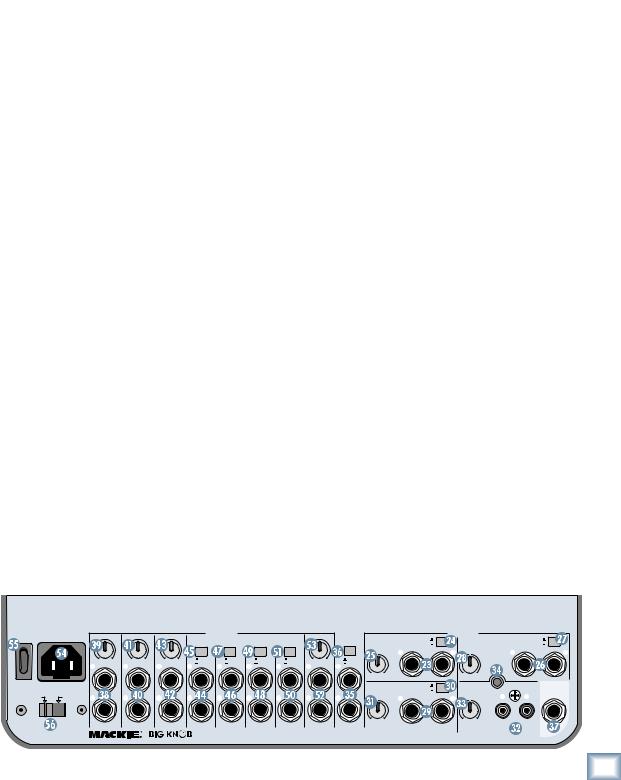
Rear Panel.................................................................................................................................................... |
9 |
Appendix A: Service Information......................................................................... |
13 |
Warranty Service...................................................................................................................................... |
13 |
Troubleshooting....................................................................................................................................... |
13 |
Repair .......................................................................................................................................................... |
14 |
Appendix B: Connections ...................................................................................... |
15 |
XLR Connectors ........................................................................................................................................ |
15 |
1/4" TRS Phone Plugs and Jacks ........................................................................................................... |
15 |
1/4" TS Phone Plugs and Jacks.............................................................................................................. |
15 |
RCA Plugs and Jacks................................................................................................................................. |
15 |
Footswitch Plug and Jack....................................................................................................................... |
15 |
Appendix C: Technical Info ................................................................................... |
16 |
Big Knob Specifications.......................................................................................................................... |
16 |
Big Knob Block Diagram......................................................................................................................... |
18 |
Big Knob Limited Warranty.................................................................................. |
19 |
Guide Operation
Please write your serial number here for future reference (i.e., insurance claims, tech support, return authorization, etc.)
Purchased at:
Date of purchase:
Don’t forget to visit our website at www.mackie.com for more information about this and other Mackie products.
Part No. 0009001 Rev. B 4/04
©2004 LOUD Technologies Inc. All Rights Reserved.
Operation Guide |
3 |
BIG KNOB
Introduction
Thank you for choosing the Mackie Big Knob, your signal routing and monitoring solution for your DAW-based studio. Big Knob provides a control room matrix and the basic features of an expensive mixer, but tailored for the requirements of your DAW (Digital Audio Workstation) environment. These features include selecting up to four separate stereo input sources, monitoring through three different speakers for A/B/C comparisons, providing a separate headphone mix and a studio output for the talent, and a built-in talkback mic for slate-to-tape and headphone cueing. In other words, it gives you everything you need from a mixer, without the stuff you don’t need!
Another important feature you’ve come to expect from Mackie is pristine sound quality, and Big Knob is no exception. This is studio-quality gear, and we made sure the audio signal suffers no degradation by passing through Big Knob. You can connect this baby between your expensive DAW and your really expensive studio monitors with no reservations. Big Knob will pass the test!
Big Knob is part of the growing family of Mackie computer recording products. Visit our website (www.mackie.com) to learn more about these products and the solutions to your audio and recording needs that Mackie has to offer, or pick up a catalog at your nearest Mackie dealer.
INPUT
 OL
OL 
8
0
4
8
 24
24 
0 = +4dBu
PHONES
1
OO
2
OO
|
INPUT SOURCE SELECT |
|
MIC |
|
POWER |
|
MONITOR SELECT |
|||
|
|
|
|
|
||||||
|
|
|
|
|
|
|||||
DAW |
2-TRACK |
2-TRACK |
PHONO |
|
|
A |
|
B |
C |
|
MIX |
A |
B |
|
|
|
|
|
|||
|
|
|
|
|
|
|
|
|||
|
|
STUDIO OUTS |
|
|
|
|
TALKBACK |
|
||
|
|
|
|
OO |
VOLUME |
MAX |
|
|
|
|
|
PHONES/ |
|
|
|
|
|
|
|
|
|
|
STUDIO OUTS |
|
|
|
|
|
|
|
|
|
|
SOURCE |
|
|
|
|
|
|
|
|
|
MAX |
|
|
|
MONO |
|
DIM |
|
|
|
|
|
INPUT SOURCE(S) |
OFF |
OO |
MAX |
MUTE |
OO |
MAX |
TO |
TO |
|
|
|
|
|
|
|
|||||
|
PHONES MIX INPUT |
ON |
LEVEL |
LEVEL |
|
2-TRACKS |
PHONES/ |
|||
|
|
|
||||||||
STUDIO
MAX
|
|
|
Getting Started |
Zero the Controls |
|
The following steps will help you set up your Big Knob and get the levels adjusted correctly. Once you have made the connections and adjustments, refer to the Features section for more in-depth information about each input, output, switch, and control knob.
Most of the inputs and outputs on Big Knob have either a trim control or a level switch labeled –10 dB and +4 dB. This actually comes from two standard operating levels that have evolved in the audio industry:
–10 dBV consumer level and +4 dBu pro-
|
|
fessional level. Most consumer equipment with RCA |
|
|
connectors operate at the –10 dBV level, while most |
|
|
professional equipment with 1/4-inch phone jacks |
|
|
or XLR connectors operate at the +4 dBu level. |
|
|
As you might expect, the +4 dBu level is higher |
|
|
(louder) than the –10 dBV level, so it is important to |
|
|
match the input and output levels of Big Knob to the |
|
|
equipment you have connected to it. For a Big Knob |
|
|
input, the –10 dB setting accepts a smaller signal |
|
|
and provides more gain than the +4 dB setting. For |
|
|
a Big Knob output, the –10 dB setting produces a |
|
|
smaller signal than the +4 dB setting. |
|
|
|
|
|
|
|
4 |
BIG KNOB |
|
|
|
1.Turn off the POWER switch  on the rear panel.
2.On the front panel, turn the Big VOLUME Knob
 and all the LEVEL controls all the way down (counterclockwise).
3.Set all the switches to the up position (front and rear panels).
4.On the rear panel, turn all the trim controls all the way down (counterclockwise).
Connections
1.Connect the supplied detachable power cord to
the AC socket  on the rear panel of Big Knob. Set the AC SELECT switch
  to the correct position that corresponds to the AC voltage you are using (100-120V or 220-240V).
For Monitoring:
2.Connect the audio outputs (stereo mix) from your DAW’s audio interface to the two DAW MIX  input jacks on the rear panel of Big Knob.
3.Connect the MONITOR A output jacks on the rear panel of Big Knob to a pair of active studio monitors (or the inputs of an amplifier that is powering a pair of passive studio monitors). These will be located at your mixing position. If you know whether the inputs to the active studio monitors (or amplifier) accept a –10 dBV
(consumer) or +4 dBu input level, set the trim
control above the MONITOR A output jacks to the appropriate position. Otherwise, leave it
at the –10 dBV position for now. You can con-
nect additional speakers to the MONITOR B and MONITOR C
 output jacks so you can hear your mix through different types of speakers.
4.If you have a separate studio for recording,
connect the STUDIO OUTS to a pair of active studio monitors (or the inputs of an amplifier that is powering a pair of passive studio monitors).
These will be located in studio for the talent.
Set the trim control  above the STUDIO OUTS output jacks to the appropriate position, or leave it at the –10 dBV position if you’re not sure.
5.If you have a headphone distribution amplifier
for monitoring while recording, connect the PHONES AMP output jacks to the inputs of the headphone amp. Set the +4/–10 level
switch

 above the PHONES AMP output jacks to the appropriate position, or leave it at the –10 position (pushed in) if you’re not sure.
For Recording
6.Connect the 2-TRACK A outputs to the linelevel inputs of any recording device, like a DAT or cassette recorder. This allows you to record
from your DAW to the recorder. Set the +4/–10
level switch  above the 2-TRACK A output jacks to the appropriate position, or leave it at the –10 position (pushed in) if you’re not sure.
7.Connect the line-level outputs from the DAT or cassette recorder to the 2-TRACK A  inputs.
8.Connect the DAW output jacks on the rear panel of Big Knob to the stereo inputs of your DAW’s audio interface. This allows you to
record from the 2-TRACK recorder back to your
DAW. Set the +4/–10 level switch above the DAW output jacks to the appropriate position, or leave it at the –10 position (pushed in) if you’re not sure.
Set the Levels
1.With everything off, turn on Big Knob’s POWER
 switch first.
2.Turn on all other external power amplifiers, active speakers, and headphone amplifiers.
3.Start playback on your DAW and play something you’ve already recorded (or a demo track). You want to be able to listen to it over the monitor speakers connected to Big Knob.
4.Press the DAW MIX

 button in the INPUT SOURCE SELECT section on the front panel. The LED above the DAW MIX button should light.
5.Press the MONITOR A 

 button in the MONITOR SELECT section on the front panel. The LED above the MONITOR A button should light.
6.If you know whether your DAW’s audio interface output is at a –10 dBV level (consumer) or a
+4 dBu level (pro), set the +4/–10 level switch
 for the DAW MIX
 inputs to the appropriate position. If you don’t know, leave it out (in the +4 dBu position). We can change it later if we need to.
7.Slowly turn up the trim control 

 for the DAW MIX input until you see the meters
 on the front panel lighting and dancing happily. Adjust the control until the meters are lighting the “0” LED regularly. You want the “+8” LED to light only occasionally, and the “OL” LED to not light at all.
8.If you can’t adjust the trim control far enough to get the signal level up to the 0 and +5 LEDs on the meter, turn the trim control all the way down, push in the +4/–10 level switch for the DAW MIX input, and slowly turn up the trim control again. Now the signal should be strong enough to get the 0 and +5 LEDs to light.
9.Slowly turn up the Big Knob VOLUME control. You should begin to hear playback from your DAW through your studio monitor speakers. Adjust the VOLUME control to a comfortable listening level. If it seems like you have to turn up the VOLUME control all the way to hear
the monitor speakers, turn down the VOLUME control and check to see if the trim control
Guide Operation
POWER |
~100-240 VAC |
MONITOR A MONITOR B MONITOR C |
OUTPUTS |
|
|
STUDIO |
DAW |
|
|
|
SOURCES |
|
|
|
||||
ON |
50/60 Hz 25W |
2-TRACK |
2-TRACK |
DAW |
PHONES |
PHONES |
2-TRACK |
+4dB |
2-TRACK |
|
|
+4dB |
||||||
|
|
|
|
|
A |
B |
OUTPUT |
AMP |
|
MIX INPUT |
|
A |
-10dB |
|
B |
|
|
-10dB |
|
|
|
|
|
|
|
|
|
|
|
|
|
(MONO) |
|
|
(MONO) |
|
|
|
|
|
|
|
|
|
|
|
|
|
|
U |
L |
R |
U |
L |
|
R |
|
|
-10dB +4dB |
-10dB +4dB |
-10dB +4dB |
+4dB |
+4dB |
+4dB |
+4dB |
-10dB +4dB |
+4dB |
|
|
|
|
|
|
|
|
|
|
L |
L |
L |
-10dB |
-10dB |
-10dB |
-10dB |
L |
-10dB |
|
|
|
|
|
|
|
|
|
|
L |
L |
L |
L |
L |
|
|
|
|
|
|
|
|
||||
|
|
|
|
|
|
|
|
|
|
|
-10dB |
+10dB |
BAL/ |
-10dB |
+10dB |
|
|
BAL/ |
|
|
|
|
|
|
|
|
|
|
|
|
|
UNBAL |
|
|
|
|
UNBAL |
AC SELECT |
|
|
|
|
|
|
|
|
|
DAW |
+4dB |
PHONO |
GROUND |
|
TALK BACK |
|||
|
|
|
|
|
|
|
|
|
-10dB |
|
|
FOOT |
||||||
|
|
|
|
|
|
|
|
|
MIX |
|
|
|||||||
100-120V |
220-240V |
|
|
|
|
|
|
|
|
|
(MONO) |
|
|
L |
R |
SWITCH |
||
R |
R |
R |
R |
R |
R |
R |
R |
R |
|
|
|
|
||||||
|
U |
L |
R |
U |
|
|||||||||||||
|
|
|
|
|
|
|||||||||||||
|
|
|
|
|
|
|
|
|
|
|
-10dB |
+10dB |
BAL/ |
-10dB |
+10dB |
RIAA |
|
|
|
|
|
|
|
|
|
|
|
|
|
|
|
|
|||||
|
|
BAL/UNBAL |
BAL/UNBAL |
BAL/UNBAL |
BAL/UNBAL |
BAL/UNBAL |
BAL/UNBAL |
BAL/UNBAL |
BAL/UNBAL |
BAL/UNBAL |
|
|
UNBAL |
|
|
|
|
|
|
|
|
|
|
|
|
|
|
|
|||||||||
DESIGNED BY MACKOIDS IN WOODINVILE, WA, USA • "BIG KNOB" & "MACKIE" ARE TRADEMARKS OF LOUD TECHNOLOGIES INC. • COPYRIGHT ©2004
Operation Guide |
5 |

BIG KNOB
above the MONITOR A output jacks is in the –10 dB position (counterclockwise). If it is, turn the control up to the +4 dB position and then turn up the Big Knob VOLUME control. Now it should get louder, faster.
10.If you have monitors connected to the STUDIO
OUTS  , make sure the PHONES/STUDIO OUTS SOURCE
  button on the front panel is out, and the STUDIO OUTS ON/OFF
  button is ON (LED above the button is lit).
11.Slowly turn up the STUDIO OUTS LEVEL  control on the front panel. You should begin to hear playback from your DAW through your studio monitor speakers. Adjust the STUDIO
OUTS LEVEL control to a comfortable listening level. If it seems like you have to turn up the LEVEL control all the way to hear the studio monitor speakers, turn down the LEVEL control
and check to see if the trim control  above the STUDIO OUTS
  jacks is in the –10 dB position (counterclockwise). If it is, turn the control
up to the +4 dB position and then turn up the LEVEL control. Now it should get louder, faster.
12.If you have a headphone distribution amplifier
connected to the PHONES AMP

 outputs, you should be able to turn up the volume for each headphone connected to the headphone amplifier and hear playback from the DAW. If it seems like you’re not getting enough volume from the headphone amplifier, turn down all the headphone volume controls on the headphone ampli-
Hookup
MONITOR A
Passive
Studio Monitors
MONITOR B |
|
|
Mackie HR824 or other |
MONITOR C |
|
Active Studio Monitors |
||
Powered |
||
|
Subwoofer |
Stereo Power
Amplifier
fier and check to see if the +4/–10 level switch

 above the PHONES AMP

 output jacks is in the –10 dB position (pushed in). If it is,
switch it to the +4 position and then turn up the headphone volume control on the headphone amplifier. Now it should get louder, faster.
13.You can connect a pair of headphones to one of the two PHONES  jacks on the front panel of Big Knob. Slowly turn up its associated LEVEL
  control to a comfortable listening level.
14.If you want to record from the DAT or cassette player to your DAW, start playback on the DAT or cassette connected to Big Knob.
CAUTION: See “A Cautionary Note” on the next page to avoid creating a feedback loop through the 2-TRACK inputs and outputs.
15.Push in the 2-TRACK A  button in the INPUT SOURCE SELECT section on the front panel and turn off the DAW MIX button. Slowly turn
up the trim control  for the 2-TRACK A input until you see the meters
  on the front panel light. Adjust the control until the meters are lighting the “0” LED regularly. You want the “+8” LED to light only occasionally, and the “OL” LED to not light at all.
16.Make sure the inputs to the DAW are selected for recording. Start recording and the playback from the 2-TRACK A input to Big Knob should be recording in the DAW application. If it seems like you’re not getting enough volume from the 2-TRACK playback, check to see if the +4/–10
level switch  above the DAW
  output jacks is in the –10 dB position (pushed in). If it is, switch it to the +4 position. This will provide a stronger signal to send to your DAW.
Headphones
Reel-to-Reel
Headphone Distribution Recorder
Amp
STUDIO MONITORS
Mackie HR824 or other
Active Studio Monitors
POWER |
~120-240 VAC |
MONITOR |
A |
MONITOR |
B |
MONITOR |
C |
OUTPUTS |
|
|
STUDIO |
DAW |
|
|
|
SOURCES |
|
|
|
|||||||
ON |
50/60 Hz 25W |
|
|
|
|
|
|
2-TRACK |
2-TRACK |
DAW |
PHONES |
|
|
PHONES |
2-TRACK |
+4dB |
2-TRACK |
|
|
+4dB |
||||||
|
|
|
|
|
|
|
|
|
|
|
|
A |
B |
OUTPUT |
AMP |
|
|
MIX INPUT |
|
A |
-10dB |
|
B |
|
|
-10dB |
|
|
|
|
|
|
|
|
|
|
|
|
|
|
|
|
|
|
|
|
|
(MONO) |
|
|
(MONO) |
|
|
|
|
|
|
|
|
|
|
|
|
|
|
|
|
|
|
|
|
|
|
U |
L |
R |
U |
L |
|
R |
|
|
|
-10dB |
+4dB |
-10dB |
+4dB |
-10dB |
+4dB |
+4dB |
+4dB |
+4dB |
+4dB |
-10dB |
+4dB |
+4dB |
|
|
|
|
|
|
|
|
|||
|
|
|
L |
|
|
L |
|
|
L |
|
|
-10dB |
-10dB |
-10dB |
-10dB |
L |
|
-10dB |
|
|
|
|
|
|
|
|
|
|
|
|
|
|
|
|
|
L |
L |
L |
L |
|
L |
|
|
|
|
|
|
|
|
||||
|
|
|
|
|
|
|
|
|
|
|
|
|
|
|
|
|
|
|
-10dB |
+10dB |
BAL/ |
-10dB |
+10dB |
|
|
BAL/ |
|
|
|
|
|
|
|
|
|
|
|
|
|
|
|
|
|
|
|
UNBAL |
|
|
UNBAL |
||||
|
AC SELECT |
|
|
|
|
|
|
|
|
|
|
|
|
|
|
|
|
|
DAW |
+4dB |
PHONO |
GROUND |
|
TALK BACK |
||
|
|
|
|
|
|
|
|
|
|
|
|
|
|
|
|
|
|
MIX |
-10dB |
|
|
FOOT |
||||
100V |
120V |
240V |
R |
|
|
R |
|
|
R |
|
|
R |
R |
R |
R |
R |
|
R |
|
|
(MONO) |
|
|
L |
R |
SWITCH |
|
|
|
|
|
|
|
|
U |
L |
R |
U |
|
||||||||||||||
|
|
|
|
|
|
|
|
|
|
|
|
|
|
|
|
|
|
|
-10dB |
+10dB |
BAL/ |
-10dB |
+10dB |
RIAA |
|
|
|
|
|
BAL/UNBAL |
|
BAL/UNBAL |
|
BAL/UNBAL |
BAL/UNBAL |
BAL/UNBAL |
BAL/UNBAL |
BAL/UNBAL |
BAL/UNBAL |
BAL/UNBAL |
|
|
UNBAL |
|
|
|
|
|
|||||
|
|
|
|
|
|
|
|
|
|
|
|
DESIGNED BY MACKOIDS IN WOODINVILE, WA, USA • "BIG KNOB" & "MACKIE" ARE TRADEMARKS OF LOUD TECHNOLOGIES INC. • COPYRIGHT ©2004 |
|
|
|
|
|
|||||||||
Turntable
Sound Card
DAT Recorder
Footswitch
LINE
OUTS
1 |
2
3
4
LINE
IN
MIC
IN
6 |
BIG KNOB |
 Loading...