


1202-VLZ3
12-Channel Mic/Line Mixer
O W N E R ’ S M A N U A L
POWER |
PHANTOM |
ON |
ON |
L MAIN
BALANCED
|
|
CAUTION |
|
WARNING: TO REDUCE THE RISK OF FIRE OR ELECTRIC SHOCK, DO NOT |
SERIAL NUMBER |
MANUFACTURING DATE |
||||
|
|
|
|
|
EXPOSE THIS EQUIPMENT TO RAIN OR MOISTURE. DO NOT REMOVE COVER. |
|
|
|
||
|
|
RISK OF ELECTRIC SHOCK |
|
NO USER SERVICEABLE PARTS INSIDE. REFER SERVICING TO QUALIFIED PERSONNEL. |
|
|
|
|||
|
|
|
DO NOT OPEN |
|
AVIS: RISQUE DE CHOC ELECTRIQUE — NE PAS OUVRIR |
|
|
|
||
|
|
|
|
|
|
|
|
|||
|
|
REPLACE WITH THE SAME TYPE FUSE AND RATING. |
|
UTILISE UN FUSIBLE DE RECHANGE DE MÊME TYPE. |
|
|
|
|||
|
|
DISCONNECT SUPPLY CORD BEFORE CHANGING FUSE |
|
DEBRANCHER AVANT DE REMPLACER LE FUSIBLE |
|
|
|
|||
|
|
|
|
|
|
XDRTM EXTENDED DYNAMIC RANGE MIC PREAMPLIFIERS ARE PROPRIETARY TO MACKIE DESIGNS, INC. |
||||
|
|
|
CONTROL |
|
|
ALT |
|
CHANNEL INSERT |
|
|
|
|
|
ROOM |
|
|
OUTPUT |
|
|
||
|
|
|
BAL/UNBAL |
|
BAL/UNBAL |
( PRE-FADER / PRE EQ |
TIP SEND / RING RETURN ) |
|||
|
|
R |
L |
R/4 |
L/3 |
4 |
3 |
2 |
1 |
|
MAIN
OUTPUT
LEVEL
|
|
M |
1 |
|
|
M |
2 |
|
|
M |
3 |
|
|
M |
4 |
||||
|
MIC |
|
|
MIC |
|
|
MIC |
|
|
MIC |
|
||||||||
|
R |
|
IC |
PRE |
|
R |
|
IC |
PRE |
|
R |
|
IC |
PRE |
|
R |
|
IC |
PRE |
|
XD |
|
|
|
XD |
|
|
|
XD |
|
|
|
XD |
|
|
||||
|
|
|
|
BAL |
|
|
|
|
BAL |
|
|
|
|
BAL |
|
|
|
|
BAL |
|
|
|
|
OR |
|
|
|
|
OR |
|
|
|
|
OR |
|
|
|
|
OR |
|
|
|
|
UNBAL |
|
|
|
|
UNBAL |
|
|
|
|
UNBAL |
|
|
|
|
UNBAL |
LINE IN 1 |
|
LINE IN 2 |
|
LINE IN 3 |
|
LINE IN 4 |
|
||||||||||||
|
|
|
LOW CUT |
|
|
|
LOW CUT |
|
|
|
LOW CUT |
|
|
|
LOW CUT |
||||
|
|
|
|
75 Hz |
|
|
|
|
75 Hz |
|
|
|
|
75 Hz |
|
|
|
|
75 Hz |
|
|
|
18dB/OCT |
|
|
|
18dB/OCT |
|
|
|
18dB/OCT |
|
|
|
18dB/OCT |
||||
|
|
|
d |
|
|
|
|
d |
|
|
|
|
d |
|
|
|
|
d |
|
|
-10GBV |
|
-10GBV |
|
-10GBV |
|
-10GBV |
||||||||||||
|
IC |
AI |
|
IC |
AI |
|
IC |
AI |
|
IC |
AI |
||||||||
U |
M |
|
|
N |
U |
M |
|
|
N |
U |
M |
|
|
N |
U |
M |
|
|
N |
|
0 |
|
60 |
|
0 |
|
60 |
|
0 |
|
60 |
|
0 |
|
60 |
||||
+15dB-45dB |
+15dB-45dB |
+15dB-45dB |
+15dB-45dB |
||||||||||||||||
|
GAIN |
|
GAIN |
|
GAIN |
|
GAIN |
||||||||||||
L /MONO |
R |
|
1 |
L |
R |
|
2 |
|
MONO |
|
L |
|
BAL |
|
OR |
|
UNBAL |
R
LINE IN 5–6
|
U |
AUX |
|
U AUX |
|
U AUX |
|
U AUX |
|
U AUX |
||||
OO |
+15 |
|
OO |
+15 |
|
OO |
+15 |
|
OO |
+15 |
|
OO |
+15 |
|
|
U |
|
|
U |
|
|
U |
|
|
U |
|
|
U |
|
OO |
+15 |
|
OO |
+15 |
|
OO |
+15 |
|
OO |
+15 |
|
OO |
+15 |
|
|
U |
EQ |
|
U |
EQ |
|
U |
EQ |
|
U |
EQ |
|
U |
EQ |
|
|
|
|
|
|
|
|
|
|
|||||
|
|
HI |
|
|
HI |
|
|
HI |
|
|
HI |
|
|
HI |
|
|
12kHz |
|
|
12kHz |
|
|
12kHz |
|
|
12kHz |
|
|
12kHz |
-15 |
+15 |
|
-15 |
+15 |
|
-15 |
+15 |
|
-15 |
+15 |
|
-15 |
+15 |
|
|
U |
|
|
U |
|
|
U |
|
|
U |
|
|
U |
|
|
|
MID |
|
|
MID |
|
|
MID |
|
|
MID |
|
|
MID |
|
|
2.5kHz |
|
|
2.5kHz |
|
|
2.5kHz |
|
|
2.5kHz |
|
|
2.5kHz |
-15 |
+15 |
|
-15 |
+15 |
|
-15 |
+15 |
|
-15 |
+15 |
|
-15 |
+15 |
|
|
U |
|
|
U |
|
|
U |
|
|
U |
|
|
U |
|
|
|
LOW |
|
|
LOW |
|
|
LOW |
|
|
LOW |
|
|
LOW |
|
|
80Hz |
|
|
80Hz |
|
|
80Hz |
|
|
80Hz |
|
|
80Hz |
-15 |
+15 |
|
-15 |
+15 |
|
-15 |
+15 |
|
-15 |
+15 |
|
-15 |
+15 |
|
|
|
PAN |
|
|
PAN |
|
|
PAN |
|
|
PAN |
|
|
PAN |
L |
R |
|
L |
R |
|
L |
R |
|
L |
R |
|
L |
R |
|
1 |
|
2 |
|
3 |
|
4 |
|
5/6 |
|
|||||
MUTE |
|
MUTE |
|
MUTE |
|
MUTE |
|
MUTE |
|
|||||
ALT 3–4 |
|
ALT 3–4 |
|
ALT 3–4 |
|
ALT 3–4 |
|
ALT 3–4 |
|
|||||
PRE FADER |
|
PRE FADER |
|
PRE FADER |
|
PRE FADER |
|
PRE FADER |
|
|||||
SOLO |
|
SOLO |
|
SOLO |
|
SOLO |
|
SOLO |
|
|||||
|
U |
|
|
U |
|
|
U |
|
|
U |
|
|
U |
|
ALL BAL/UNBAL |
TAPE |
TAPE |
BAL/UNBAL |
1 |
INPUT |
OUTPUT |
L |
|
L |
|
L |
2 |
|
|
R |
|
R |
|
R |
AUX SEND |
|
|
MAIN OUT |
MONO |
|
MONO |
MONO |
L |
|
L |
L |
BAL |
|
BAL |
BAL |
OR |
|
OR |
OR |
UNBAL |
|
UNBAL |
UNBAL |
R |
|
R |
R |
LINE IN 7–8 |
LINE IN 9–10 LINE IN 11–12 |
||
|
U AUX |
|
U AUX |
|
U AUX |
|
|
|
|||
OO |
+15 |
|
OO |
+15 |
|
OO |
+15 |
|
|
|
|
|
U |
|
|
U |
|
|
U |
|
|
|
|
OO |
+15 |
|
OO |
+15 |
|
OO |
+15 |
|
|
|
|
|
U |
EQ |
|
U |
EQ |
|
U |
EQ |
POWER |
|
|
|
|
|
|
|
|
|
|
||||
|
|
HI |
|
|
HI |
|
|
HI |
|
|
|
|
|
|
|
|
|
|
LEFT RIGHT |
|
|||
|
|
12kHz |
|
|
12kHz |
|
|
12kHz |
CONTROL |
|
|
|
|
|
|
|
|
|
|
|
0dB=0dBu |
|
|
-15 |
+15 |
|
-15 |
+15 |
|
-15 |
+15 |
|
ROOM |
|
|
|
U |
|
|
U |
|
|
U |
|
SOURCE |
20 |
CLIP |
|
|
MID |
|
|
MID |
|
|
MID |
|
10 |
|
|
|
2.5kHz |
|
|
2.5kHz |
|
|
2.5kHz |
|
7 |
|
|
|
|
|
|
|
|
|
|
MAIN MIX |
|
|
-15 |
+15 |
|
-15 |
+15 |
|
-15 |
+15 |
|
|
|
|
|
|
|
|
4 |
|
||||||
|
U |
|
|
U |
|
|
U |
|
|
|
|
|
|
|
|
|
|
|
|
|
|||
|
|
LOW |
|
|
LOW |
|
|
LOW |
|
2 |
|
|
|
|
|
|
|
ALT 3–4 |
|
|
|||
|
|
80Hz |
|
|
80Hz |
|
|
80Hz |
0 |
|
|
-15 |
+15 |
|
-15 |
+15 |
|
-15 |
+15 |
|
|
2 |
|
|
|
PAN |
|
|
PAN |
|
|
PAN |
TAPE |
4 |
|
|
|
|
|
|
|
|
|
|
|
7 |
LEVEL |
|
|
|
|
|
|
|
|
|
|
10 |
SET |
L |
R |
|
L |
R |
|
L |
R |
|
|
|
|
|
|
|
|
20 |
|
||||||
7/8 |
|
9/10 |
|
11/12 |
|
|
|
||||
|
|
|
|
30 |
|
||||||
MUTE |
|
MUTE |
|
MUTE |
|
|
|
|
|||
ALT 3–4 |
|
ALT 3–4 |
|
ALT 3–4 |
|
ASSIGN |
RUDE |
|
|||
|
|
|
|
|
|
|
|
|
TO MAIN MIX |
|
|
PRE FADER |
|
PRE FADER |
|
PRE FADER |
|
|
SOLO |
|
|||
|
|
|
|
LIGHT |
|
||||||
SOLO |
|
SOLO |
|
SOLO |
|
|
|
||||
|
|
|
|
|
|
||||||
|
U |
|
|
U |
|
|
U |
|
U |
U |
|
OO |
+12dB |
LEVEL
OO |
+12dB |
LEVEL
OO |
+12dB |
LEVEL
OO |
+12dB |
LEVEL
OO |
+12dB |
LEVEL
OO |
+12dB |
LEVEL
OO |
+12dB |
LEVEL
OO |
+12dB |
LEVEL
OO |
MAX |
CTL ROOM /SUBMIX
OO |
+12dB |
MAIN MIX
1202-VLZ3
Important Safety Instructions
1.Read these instructions.
2.Keep these instructions.
3.Heed all warnings.
4.Follow all instructions.
5.Do not use this apparatus near water.
6.Clean only with dry cloth.
7.Do not block any ventilation openings. Install in accordance with the manufacturer’s instructions.
8.Do not install near any heat sources such as radiators, heat registers, stoves, or other apparatus (including amplifiers) that produce heat.
9.Do not defeat the safety purpose of the polarized or grounding-type plug. A polarized plug has two blades with one wider than the other. A grounding-type plug has two blades and a third grounding prong. The wide blade or the third prong are provided for your safety. If the provided plug does not fit into your outlet, consult an electrician for replacement of the obsolete outlet.
10.Protect the power cord from being walked on or pinched particularly at plugs, convenience receptacles, and the point where they exit from the apparatus.
11.Only use attachments/accessories specified by the manufacturer.
12.Use only with a cart, stand, tripod, bracket, or table specified by the manufacturer, or sold with the apparatus. When a cart is used, use caution when moving the cart/apparatus combination to avoid injury from tip-over.
PORTABLE CART WARNING
Carts and stands - The Component should be used only with a cart or stand that is recommended by the manufacturer.
A Component and cart combination should be moved with care. Quick stops, excessive force, and uneven surfaces may cause the Component and cart combination to overturn.
13.Unplug this apparatus during lightning storms or when unused for long periods of time.
14.Refer all servicing to qualified service personnel. Servicing is required when the apparatus has been damaged in any way, such as powersupply cord or plug is damaged, liquid has been spilled or objects have fallen into the apparatus, the apparatus has been exposed to rain or moisture, does not operate normally, or has been dropped.
15.This apparatus shall not be exposed to dripping or splashing, and no object filled with liquids, such as vases or beer glasses, shall be placed on the apparatus.
16.This apparatus has been designed with Class-I construction and must be connected to a mains socket outlet with a protective earthing connection (the third grounding prong).
17.This apparatus has been equipped with an all-pole, rocker-style AC mains power switch. This switch is located on the rear panel and should remain readily accessible to the user.
18.This apparatus does not exceed the Class A/Class B (whichever is applicable) limits for radio noise emissions from digital apparatus as set out in the radio interference regulations of the Canadian Department of Communications.
ATTENTION — Le présent appareil numérique n’émet pas de bruits radioélectriques dépassant las limites applicables aux appareils numériques de class A/de class B (selon le cas) prescrites dans le réglement sur le brouillage radioélectrique édicté par les ministere des communications du Canada.
19.Exposure to extremely high noise levels may cause permanent hearing loss. Individuals vary considerably in susceptibility to noise-induced hearing loss, but nearly everyone will lose some hearing if exposed to sufficiently intense noise for a period of time. The U.S. Government’s Occupational Safety and Health Administration (OSHA) has specified the permissible noise level exposures shown in the following chart.
According to OSHA, any exposure in excess of these permissible limits could result in some hearing loss. To ensure against potentially dangerous exposure to high sound pressure levels, it is recommended that all persons exposed to equipment capable of producing high sound pressure levels use hearing protectors while the equipment is in operation. Ear plugs or protectors in the ear canals or over the ears must be worn when operating the equipment in order to prevent permanent hearing loss if exposure is in excess of the limits set forth here.
CAUTION |
AVIS |
Duration Per Day |
Sound Level dBA, |
Typical |
|
In Hours |
Slow Response |
Example |
|||
RISK OF ELECTRIC SHOCK |
8 |
90 |
Duo in small club |
||
DO NOT OPEN |
|||||
RISQUE DE CHOC ELECTRIQUE |
6 |
92 |
|
||
NE PAS OUVRIR |
|
||||
4 |
95 |
Subway Train |
|||
CAUTION: TO REDUCE THE RISK OF ELECTRIC SHOCK |
|||||
3 |
97 |
|
|||
DO NOT REMOVE COVER (OR BACK) |
|
||||
NO USER-SERVICEABLE PARTS INSIDE |
2 |
100 |
Very loud classical music |
||
REFER SERVICING TO QUALIFIED PERSONNEL |
|||||
ATTENTION: POUR EVITER LES RISQUES DE CHOC |
1.5 |
102 |
|
||
ELECTRIQUE, NE PAS ENLEVER LE COUVERCLE. AUCUN |
1 |
105 |
Dave screaming at Steve about deadlines |
||
ENTRETIEN DE PIECES INTERIEURES PAR L'USAGER. CONFIER |
|||||
L'ENTRETIEN AU PERSONNEL QUALIFIE. |
0.5 |
110 |
|
||
AVIS: POUR EVITER LES RISQUES D'INCENDIE OU |
|
||||
D'ELECTROCUTION, N'EXPOSEZ PAS CET ARTICLE |
0.25 or less |
115 |
Loudest parts at a rock concert |
||
A LA PLUIE OU A L'HUMIDITE |
|||||
|
|
|
|||
|
|
The lightning flash with arrowhead symbol within an equilateral |
|
|
triangle is intended to alert the user to the presence of uninsulated |
|
|
"dangerous voltage" within the product's enclosure, that may be |
|
|
of sufficient magnitude to constitute a risk of electric shock to persons. |
|
|
Le symbole éclair avec point de flèche à l'intérieur d'un triangle |
|
|
équilatéral est utilisé pour alerter l'utilisateur de la présence à |
|
|
l'intérieur du coffret de "voltage dangereux" non isolé d'ampleur |
|
|
suffisante pour constituer un risque d'éléctrocution. |
|
|
The exclamation point within an equilateral triangle is intended to |
|
|
alert the user of the presence of important operating and maintenance |
|
|
(servicing) instructions in the literature accompanying the appliance. |
|
|
Le point d'exclamation à l'intérieur d'un triangle équilatéral est |
|
|
employé pour alerter les utilisateurs de la présence d'instructions |
|
|
importantes pour le fonctionnement et l'entretien (service) dans le |
|
|
livret d'instruction accompagnant l'appareil. |
|
|
|
|
2 |
1202-VLZ3 |
|
|
|
WARNING — To reduce the risk of fire or electric shock, do not expose this apparatus to rain or moisture.

Read This Page!
We realize that you must be dying to
try out your new 1202-VLZ3. All we ask is
that you read this page NOW, and the rest can wait until you’re good and ready. But
do read it — you’ll be glad you did.
WARNING: Before you plug the AC power
cord into the mixer, make sure the VOLTAGE SELECTOR switch is set to the same voltage
as your local AC mains supply (see page 12).
Level-Setting Procedure
Message to seasoned pros: do not set levels using the old “Turn the GAIN up until the clip light comes on, then back off a hair” trick. When a Mackie mixer clip light comes on, you really are about to clip. We worked and slaved to come up with a better system, one that provides low noise and high headroom.
Adjusting input levels (Chs. 1–4 only)
On the first four channels, it’s not even necessary to hear what you’re doing to set optimal levels. But if you’d like to: Plug headphones into the PHONES jack, then set the CONTROL ROOM/SUBMIX knob about one-quar- ter of the way up.
The following steps must be performed one channel at
atime:
1.Turn the GAIN, LEVEL and AUX send knobs fully down (counterclockwise).
2.Set the EQ knobs at the center detent.
3.Connect the signal source to the input.
4.Engage (push in) the SOLO switch.
5.Play something into the selected input. This could be an instrument, a singing or speaking voice, or a line input such as a CD player or tape recorder output. Be sure that the volume of the input is the same as it would be during normal use. If it isn’t, you might have to readjust these levels during the middle of the set.
6.Adjust the channel’s GAIN control so that the display on the right LED meter stays around “0” and never goes higher than “+7.”
7.If you’d like to apply some EQ, do so now and return to step 6.
Other Nuggets of Wisdom
For optimum sonic performance, the channel LEVEL knobs and the MAIN MIX knob should be set near the “U” (unity gain) markings.
Always turn the MAIN MIX and CONTROL ROOM/ SUBMIX level controls down before making connections to and from your 1202-VLZ3.
If you shut down your equipment, turn off your amplifier or powered speakers first. When powering up, turn them on last.
Save the shipping box! You may need it someday.
Instant Mixing
Here’s how to get going right away, assuming you have a microphone and a keyboard:
1.Plug your microphone into channel 1’s MIC input.
2.Turn on the 1202-VLZ3.
3.Perform the Level-Setting Procedure.
4.Connect cords from the MAIN OUTS (XLR, 1⁄4" or RCA, your choice) to your amplifier.
5.Hook up speakers to the amp and turn it on.
6.Turn up the 1202-VLZ3’s channel 1 LEVEL knob to the center detent and the MAIN MIX knob one quarter of the way up.
7.Sing like a canary!
8.Plug your keyboard into stereo channel 5-6.
9.Turn that channel’s LEVEL knob to the center detent.
10.Play like a madman and sing like a canary! It’s your first mix!
Please write your serial number here for future reference (i.e., insurance claims, tech support, return authorization, make dad proud, etc.)
Purchased at:
Manual Owner’s
8.Disengage that channel’s SOLO switch.
9.Repeat for each of channels 1 through 4.
Date of purchase:
Part No. 0019814 Rev. A
©2006 LOUD Technologies Inc. All Rights Reserved.
(Only trained professional union stunt hamsters were used to staple this manual.)
Owner’s Manual |
3 |

1202-VLZ3
Introduction
Thank you for choosing a Mackie professional compact mixer. The 1202-VLZ3 is equipped with our pre- cision-engineered XDRTM Extended Dynamic Range premium studio-grade mic preamp.
Now that you have your 1202-VLZ3, find out how to get the most from it. That’s where this manual comes in.
How To Use This Manual
Since many of you folks will want to hook up your 1202-VLZ3 immediately, the first pages you will encounter after the table of contents are the ever-popular hookup diagrams. These show typical mixer setups for Record/Mixdown, and Stereo PA.
After this section is a detailed tour of the entire mixer. Every feature of the 1202-VLZ3 is described “geographically;” in other words, in order of where it is physically placed on the mixer’s top or rear panel. These descriptions are divided into the first three sections, just as your mixer is organized into three distinct zones:
Patchbay: The patchbay along the top and back, where you connect things.
Channel Strip: The eight channel strips where you adjust each channel.
Output Section: The output section on the right.
Throughout these sections you’ll find illustrations, with each feature numbered. If you’re curious about a feature, simply locate it on the appropriate illustration, notice the number attached to it, and find that number in the nearby paragraphs.
 This icon marks information that is critically
  important or unique to the 1202-VLZ3. For your
  own good, read them and remember them. They will be on the final test.
This icon will lead you to in-depth explanations of features and practical tips. While not mandatory, they usually have some valuable nuggets of information.
Appendix A is a section on troubleshooting and repair information.
Appendix B is a section on connectors: XLR connectors, TRS balanced connectors, TS unbalanced connectors, and Insert connectors.
Appendix C shows the technical specifications, and a block diagram showing the internal signal path and general goings-on within the mixer.
Need help with your new mixer?
•Visit www.mackie.com and click Support to find:
FAQs (Frequently Asked Questions), manuals, addendums, and user forums.
•Email us at: techmail@mackie.com.
•Telephone 1-800-898-3211 to speak with one of our splendid technical support representatives, (Monday through Friday, from 7 a.m. to 5 p.m. PST).
4 |
1202-VLZ3 |

Contents
Important Safety Instructions .................................. |
2 |
Output Section ...................................................... |
16 |
||
Read This Page! ...................................................... |
3 |
32. |
MAIN MIX ............................................. |
16 |
|
Introduction ............................................................ |
4 |
33. |
CONTROL ROOM SOURCE MATRIX.......... |
16 |
|
Hookup Diagrams.................................................... |
6 |
34. |
CONTROL ROOM/SUBMIX ..................... |
16 |
|
Patchbay Description............................................... |
8 |
|
A WORD ABOUT PRE-FADER SOLO (PFL) |
17 |
|
1. |
MIC INPUTS (Channels 1–4)...................... |
8 |
35. |
RUDE SOLO LIGHT.................................. |
17 |
2. |
LINE INPUTS (Channels 1–4)..................... |
8 |
36. |
ASSIGN TO MAIN MIX............................ |
17 |
3. |
LOW CUT (Channels 1–4).......................... |
9 |
37. |
METERS – MANY DISPLAYS IN ONE! ....... |
17 |
4. |
GAIN (Channels 1–4) ............................... |
9 |
38. |
PRE or POST (AUX 1) ............................ |
18 |
5. |
STEREO LINE INPUTS ................................ |
9 |
39. |
AUX 1 MASTER...................................... |
18 |
6. |
IMAGINARY CONTROL ............................ |
9 |
40. |
STEREO RETURNS................................... |
18 |
|
EFFECTS: SERIAL OR PARALLEL? ................ |
9 |
41. |
RETURN TO AUX 1 ................................. |
19 |
7. |
STEREO RETURNS................................... |
10 |
|
JACK NORMALLING................................ |
19 |
8. |
AUX SEND 1&2...................................... |
10 |
Appendix A: Service Information ............................ |
20 |
|
9. |
TAPE INPUT ........................................... |
10 |
Appendix B: Connections........................................ |
21 |
|
10. |
TAPE OUTPUT ........................................ |
10 |
Appendix C: Technical Information .......................... |
24 |
|
11. |
1⁄4" MAIN OUTS ..................................... |
10 |
Specifications.................................................. |
24 |
|
12. |
PHONES ................................................ |
11 |
Block Diagram................................................. |
25 |
|
13. |
XLR MAIN OUTS ................................... |
11 |
Track Sheet..................................................... |
26 |
|
14. |
XLR MAIN OUTPUT LEVEL SWITCH.......... |
11 |
1202-VLZ3 Limited Warranty................................ |
27 |
|
15. |
CONTROL ROOM.................................... |
11 |
|
|
|
16. |
ALT 3–4 OUTPUT ................................... |
11 |
|
|
|
17. |
CHANNEL INSERT (Channels 1–4 )........... |
11 |
|
|
|
18. |
POWER CONNECTION............................. |
12 |
|
|
|
19. |
FUSE...................................................... |
12 |
|
|
|
20. |
VOLTAGE SELECTOR................................ |
12 |
|
|
|
21. |
POWER SWITCH..................................... |
12 |
|
|
|
22. |
PHANTOM SWITCH ................................ |
12 |
|
|
|
Channel Strip Description ....................................... |
13 |
|
|
|
|
|
“U” LIKE UNITY GAIN............................. |
13 |
|
|
|
23. LEVEL...................................................... |
13 |
|
|
|
|
24. |
PRE-FADER SOLO ................................... |
13 |
|
|
|
25. |
MUTE/ALT 3–4 ...................................... |
13 |
|
|
|
26. |
PAN....................................................... |
14 |
|
|
|
|
CONSTANT LOUDNESS ! ! ! ...................... |
14 |
|
|
|
|
3-BAND EQ ............................................ |
14 |
|
|
|
27. |
LOW EQ................................................. |
14 |
|
|
|
28. |
MID EQ.................................................. |
14 |
|
|
|
29. |
HI EQ..................................................... |
15 |
|
|
|
|
MODERATION DURING EQ ...................... |
15 |
|
|
|
30. |
AUX 2 SEND .......................................... |
15 |
|
|
|
31. |
AUX 1 SEND .......................................... |
15 |
|
|
|
Manual Owner’s
Owner’s Manual |
5 |
1202-VLZ3
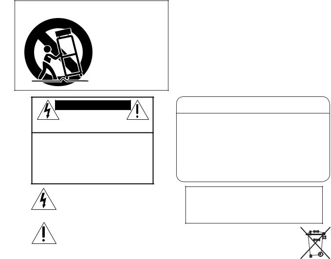
Hookup Diagrams
Vocal Mics
Direct
Boxes
Stereo Guitar Effects
Drum Machine
Keyboard or other line level input
Tape Player |
Out |
(play) |
In (record)
1 |
1 |
|
|
|
|
||
2 |
2 |
|
|
|
|
||
3 |
3 |
|
|
|
|
||
4 |
4 |
|
|
|
|
||
5 |
L |
|
|
MONO |
|||
7 |
L |
CHANNEL |
|
6 |
R |
|
|
|
MONO |
||
8 |
R |
INPUTS |
|
|
|||
9 |
L |
|
|
MONO |
|||
10 |
R |
|
|
11 |
L |
|
|
|
MONO |
||
12 |
R |
|
|
L |
R |
OUT-TAPE-IN |
|
L |
R |
||
|
|||
|
PHONES OUT |
||
|
OUTPUTS |
RM CONTROL |
|
|
INSERTS |
1 |
In |
Mono Compressor |
|
Out |
|
||
|
|
|
||
|
|
|
|
|
|
CHANNEL |
2 |
|
|
|
3 |
In |
Stereo Compressor |
|
|
|
|||
|
|
Out |
||
|
|
4 |
In |
|
|
|
Out |
|
|
|
RETURNS |
|
|
|
|
L |
|
|
|
|
|
1 |
|
|
|
|
R |
|
|
|
STEREO |
L |
Digital Delay |
|
|
|
|
||
|
|
2 |
|
|
|
|
R |
|
Multi Effect |
|
|
|
|
|
AUX |
SEND |
1 |
|
Processor |
|
|
|||
|
|
|
|
|
|
|
2 |
|
|
ALT 3-4 |
OUT |
L |
|
|
R |
|
|
||
MAIN OUT |
L |
|
|
|
R |
|
|
||
|
|
|
|
|
MAIN OUT |
|
|
|
|
|
|
Headphones |
|
|
|
for Studio |
|
Powered |
|
Powered |
|
Studio Monitors |
Headphone Distribution Amp |
||
Studio Monitors |
|||
|
|
for Studio |
Recording System
6 |
1202-VLZ3 |
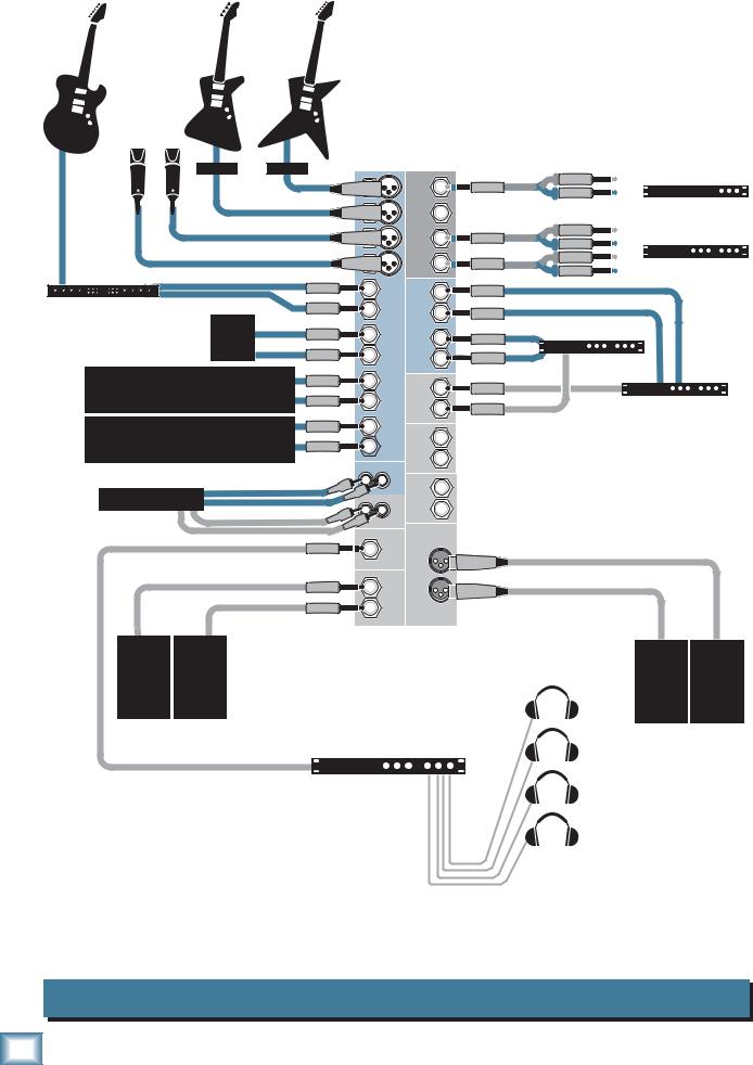
Bass Guitar
Guitar dad bought you for your birthday
Vocal Mics
Direct
Boxes
Stereo Guitar Effects
Drum
Machine
Keyboard or other line level input
Tape Player |
Out |
|
(play) |
||
|
In (record)
Way-cooler Guitar dad bought your kid brother for his
birthday
1 |
1 |
|
|
|
|
||
2 |
2 |
|
|
|
|
||
3 |
3 |
|
|
|
|
||
4 |
4 |
|
|
|
|
||
5 |
L |
|
|
MONO |
|||
7 |
L |
CHANNEL |
|
6 |
R |
|
|
|
MONO |
||
8 |
R |
INPUTS |
|
|
|||
9 |
L |
|
|
MONO |
|||
10 |
R |
|
|
11 |
L |
|
|
|
MONO |
||
12 |
R |
|
|
L |
R |
OUT-TAPE-IN |
|
L |
R |
||
|
|||
|
PHONES OUT |
||
|
OUTPUTS |
ROOM CNTRL |
|
INSERTS |
1 |
|
In |
Mono Compressor |
|
Out |
|
||
|
|
|
|
|
CHANNEL |
2 |
|
|
|
3 |
|
In |
Stereo Compressor |
|
|
|
|||
|
|
Out |
||
|
4 |
|
In |
|
|
|
Out |
|
|
RETURNS |
|
|
|
|
L |
|
|
|
|
|
1 |
|
|
|
STEREO |
R |
|
|
|
L |
|
|
|
|
|
2 |
|
|
|
|
R |
|
|
|
AUX SEND |
1 |
|
|
Multi Effect |
2 |
|
|
Processor |
|
|
|
|
||
|
|
|
|
|
ALT 3/4 OUT |
L |
|
Mono Power Stage Monitors |
|
|
Mono EQ |
|||
R |
Amplifier |
|||
MAIN OUT |
L |
|
|
|
R |
|
|
|
|
|
|
|
|
|
MAIN OUT |
|
|
|
|
Headphones
This setup can be easily reconfigured to become a Mono PA setup.
A.Stereo sources should feed the left mono side of channel input only.
B.Pan each channel hard left.
C.Connect Mono PA system to Left main output.
|
Stereo |
|
EQ |
SRM450 |
SRM450 |
Powered |
Powered |
Speaker |
Speaker |
SWA1501 |
SWA1501 |
Powered |
Powered |
Subwoofer |
Subwoofer |
Manual Owner’s
Live Stereo PA System
Owner’s Manual |
7 |
1202-VLZ3
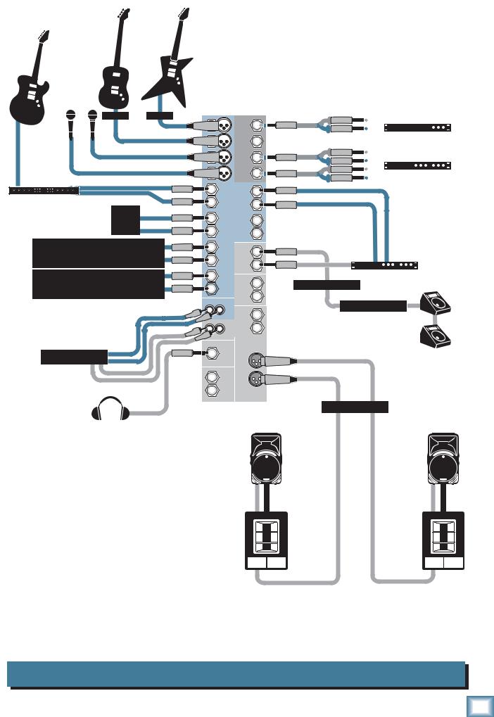
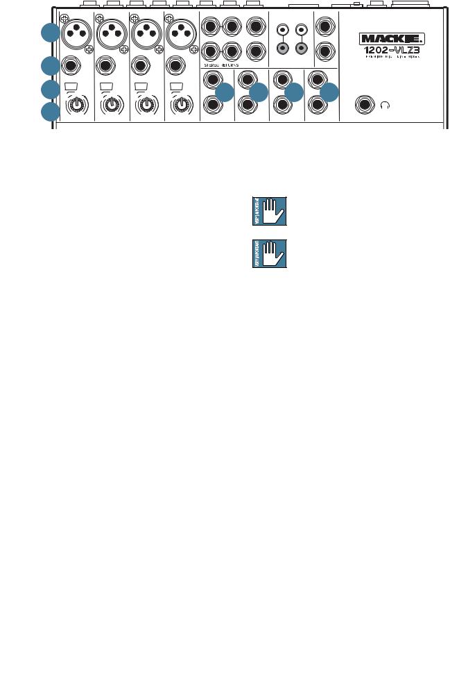
Patchbay Description
|
MICM 1 |
MICM 2 |
MICM 3 |
MICM 4 |
L /MONO |
R |
ALL BAL/UNBAL |
|
TAPE |
TAPE |
|
BAL/UNBAL |
||||
|
DR |
IC P |
DR |
IC P |
DR |
IC P |
DR |
IC P |
|
1 |
1 |
|
INPUT |
OUTPUT |
L |
|
1 |
X |
RE |
X |
RE |
X |
RE |
X |
RE |
|
|
||||||
|
|
|
|
|
|
|
|
L |
R |
|
L |
|
|
|
L |
|
|
|
|
|
|
|
|
|
|
|
2 |
2 |
|
|
|
|
R |
|
|
|
|
|
|
|
|
|
|
|
|
R |
|
|
|
R |
2 |
|
BAL |
|
BAL |
|
BAL |
|
BAL |
|
|
AUX SEND |
|
|
|
|
MAIN OUT |
|
OR |
|
OR |
|
OR |
|
OR |
|
|
|
|
|
|
|||
|
UNBAL |
|
UNBAL |
|
UNBAL |
|
UNBAL |
|
MONO |
MONO |
|
|
MONO |
|
MONO |
|
|
|
|
|
|
|
|
|
|
|
|
|
|||||
3 |
LINE IN 1 |
LINE IN 2 |
LINE IN 3 |
LINE IN 4 |
|
L |
L |
|
|
L |
|
L |
||||
U M |
LOW CUT |
U M |
LOW CUT |
U M |
LOW CUT |
U M |
LOW CUT |
|
5 |
5 |
|
|
5 |
|
5 |
|
75 Hz |
75 Hz |
75 Hz |
75 Hz |
|
|
|
|
|||||||||
|
18dB/OCT |
|
18dB/OCT |
|
18dB/OCT |
|
18dB/OCT |
|
BAL |
BAL |
|
|
BAL |
|
BAL |
|
-10 |
d |
-10 |
d |
-10 |
d |
-10 |
d |
|
OR |
OR |
|
|
OR |
|
OR |
|
BV |
BV |
BV |
BV |
|
UNBAL |
UNBAL |
|
|
UNBAL |
|
UNBAL |
|||||
IC GAIN |
IC GAIN |
IC GAIN |
IC GAIN |
|
|
|
|
|||||||||
4 |
|
|
|
|
|
|
|
|
|
R |
R |
|
|
R |
|
R |
0 |
60 |
0 |
60 |
0 |
60 |
0 |
60 |
|
|
|
|
|
|
|
|
|
+15dB-45dB |
+15dB-45dB |
+15dB-45dB |
+15dB-45dB |
LINE IN 5–6 |
LINE IN 7–8 |
LINE IN 9–10 |
LINE IN 11–12 |
|||||||||
GAIN |
GAIN |
GAIN |
GAIN |
|||||||||||||
At the risk of stating the obvious, this is where you plug everything in: microphones, line-level instruments and effects, headphones, and the ultimate destination for your sound: a tape recorder, PA system, etc.
See Appendix B for further details and drawings of the connectors you can use with the 1202-VLZ3. Also see the Channel Strip description on page 13 for details of the signal routing from the XLR and Line inputs.
1. MIC INPUTS (Channels 1–4)
We use phantom-powered, balanced microphone inputs just like the big studio mega-consoles, for exactly the same reason: This kind of circuit is excellent at rejecting hum and noise. You can plug in almost any kind of mic that has a standard XLR male mic connector.
Professional ribbon, dynamic, and condenser mics will all sound excellent through these inputs. The 1202-VLZ3’s mic inputs will handle any kind of mic level you can toss at them, without overloading. Be sure to perform the Level-Setting Procedure on page 3.
Not every instrument is made to connect directly to a mixer. Guitars commonly need a Direct Injection (DI) box to connect to the mixer's MIC inputs. These boxes convert unbalanced line-level signals from your guitar, into balanced mic-level outputs, and provide signal and impedance matching. They also let you send your gifted guitar renditions over long cables or audio snakes, with minimum interference and high-frequency signal loss. Ask your dealer or guitar maker about their recommendations for a good DI box.
PHANTOM POWER
Most modern professional condenser mics are
|
|
equipped for phantom power, which lets the mixer |
|
|
send low-current DC voltage to the mic’s electronics |
|
|
through the same wires that carry audio. (Semi-pro |
|
|
condenser mics often have batteries to accomplish the |
|
|
same thing.) “Phantom” owes its name to an ability to |
|
|
be “unseen” by dynamic mics (Shure SM57/SM58, for |
|
|
instance), which don’t need external power and aren’t |
|
|
affected by it anyway. |
|
|
|
|
|
|
|
8 |
1202-VLZ3 |
|
|
|
The 1202-VLZ3’s phantom power is globally controlled by the PHANTOM [22] switch on the rear panel. (This means the phantom power for channels 1-4 is turned on and off together.)
Never plug single-ended (unbalanced) microphones or instruments into the MIC [1] input jacks if the phantom power is on.
Do not plug instrument outputs into the MIC input jacks with phantom power on, unless you know for certain it is safe to do so.
2. LINE INPUTS (Channels 1–4)
These four line-inputs share circuitry (but not phantom power) with the mic preamps, and can be driven by balanced or unbalanced sources at almost any level. You can use these inputs for virtually any signal you’ll come across, from instrument levels as low as –40 dB to operating levels of –10 dBV to +4 dBu, since there is 40 dB more gain available than on channels 5–12.
To connect balanced lines to these inputs, use a 1⁄4" Tip-Ring-Sleeve (TRS) plug, the type found on stereo headphones.
To connect unbalanced lines to these inputs, use a 1⁄4" mono (TS) phone plug or standard instrument cable.
The LINE IN inputs 1–4 are a good place to connect older instruments that need more gain. You can correct weak levels by adjusting the corresponding channel’s GAIN control.
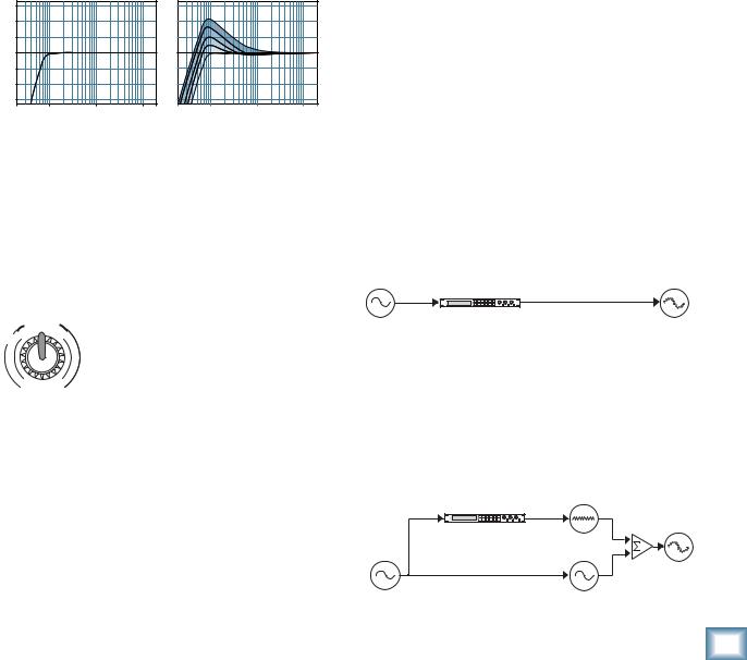
3. LOW CUT (Channels 1–4)
Each LOW CUT switch, often referred to as a High Pass Filter (all depends on how you look at it), cuts bass frequencies below 75 Hz at a rate of 18 dB per octave.
We recommend that you use low-cut on every microphone application except kick drum, bass guitar, bassy synth patches, or recordings of earthquakes. These aside, there isn’t much down there that you want to hear, and filtering it out makes the low stuff you do want much more crisp and tasty. Not only that, but low-cut can help reduce the possibility of feedback in live situations, and it helps to conserve amplifier power.
Another way to consider low-cut’s function is that it actually adds flexibility during live performances. With the addition of low-cut, you can safely use low equalization on vocals. Many times, bass shelving EQ can really benefit voices. Trouble is, adding low EQ also boosts stage rumble, mic handling clunks and breath pops. Applying low-cut removes all those problems, so you can add low EQ without losing a woofer.
Here’s what the combination of low EQ and low-cut looks like in terms of frequency curves:
+15 |
|
|
+15 |
|
|
|
+10 |
|
|
+10 |
|
|
|
+5 |
|
|
+5 |
|
|
|
0 |
|
|
0 |
|
|
|
–5 |
|
|
–5 |
|
|
|
–10 |
|
|
–10 |
|
|
|
–15 |
|
|
–15 |
|
|
|
20Hz |
100Hz |
1kHz |
10kHz 20kHz 20Hz |
100Hz |
1kHz |
10kHz 20kHz |
Low Cut |
|
Low Cut with Low EQ |
|
|||
4. GAIN (Channels 1–4)
If you haven’t already, please read the Level-Setting Procedure on page 3.
GAIN adjusts the input sensitivity of the mic and line inputs connected to channels 1 through 4. This allows signals from the outside world to be adjusted to optimal internal operating levels.
|
-1 |
d |
V |
If the signal originates through the |
|
0 |
B |
|
|
|
IC |
G |
|
|
|
AI |
|
||
U |
M |
|
N |
XLR jack, there will be 0 dB of gain with |
|
|
|
||
|
|
|
|
the knob fully down, ramping to 60 dB |
|
0 |
|
60 |
of gain fully up. |
+15dB-45dB |
|
|||
|
GAIN |
Through the 1⁄4" input, there is 15 |
||
dB of attenuation fully down and 45 dB of gain fully up, with a “U” (unity gain) mark at 10:00. This 15 dB of attenuation can be very handy when you are inserting a very hot signal, or when you want to add a lot of EQ gain, or both. Without this “virtual pad,” this scenario might lead to channel clipping.
5. STEREO LINE INPUTS
(Channels 5–6, 7–8, 9–10 and 11–12)
These fully balanced inputs are designed for stereo or mono, balanced or unbalanced signals, from –10 dBV to +4 dBu. They can be used with just about any professional or semi-pro instrument, effect or tape player.
In the stereo audio world, an odd-numbered channel usually receives the “left signal.” For example, you would feed the 1202-VLZ3’s line inputs 5-6 a stereo signal by inserting the device’s left output plug into the channel 5 jack, and its right output plug into the channel 6 jack.
When connecting a mono device (just one cord), always use the LEFT (MONO) input (jacks 5, 7, 9 or 11) and plug nothing into the RIGHT input (jacks 6, 8, 10 or 12)— this way the signal will appear on both sides. This trick is called “jack normalling.”
6. IMAGINARY CONTROL
This control is purely a figment of our imagination. It will come in handy after long hours of mixing, when you really would like a nice cup of tea, a vacation in Hawaii, or a trip to the outer reaches of the Solar System. This is the control for you. Be thankful, you bought a Mackie. We love you man!
EFFECTS: SERIAL OR PARALLEL?
The next two sections toss the terms “serial” and “parallel” around like hacky sacks. Here’s what we mean by them:
“Serial” means that the entire signal is routed through the effects device. Examples: compressor/limiters, graphic equalizers. Line-level sources can be patched through a serial effects device before or after the mixer, or preferably through the insert jacks located on the rear panel (CHANNEL INSERT [17] send/return).
|
Insert |
Insert |
|
Send |
Return |
|
Signal Processor |
|
Dry Signal |
(e.g., Compressor) |
Processed |
|
|
Signal |
“Parallel” means that a portion of the signal in the mixer is tapped off to the device (AUX SEND), processed and returned to the mixer (STEREO RETURN) to be mixed with the original “dry” signal. This way, multiple channels can all make use of the same effects device. Examples: reverb, digital delay.
Aux |
Aux |
Output |
|
Send |
Return |
Section |
|
Signal Processor |
|
|
|
(e.g., Reverb) |
|
Wet Signal |
|
|
|
Mix |
Processed |
Channel Path |
|
Stage |
Signal |
|
|
|
|
Dry Signal(s) |
|
Dry Signal(s) |
|
Manual Owner’s
Owner’s Manual |
9 |
 Loading...