


D50 and D60 Harvest Headers®
For Self-Propelled Windrowers
OPERATOR’S MANUAL
Revision B
Part #169441 $15
This Manual contains instructions for “SAFETY”, “OPERATION”, and “MAINTENANCE/SERVICE” information for your new MacDon Models D50 and D60 Harvest Header® for self-propelled windrowers.
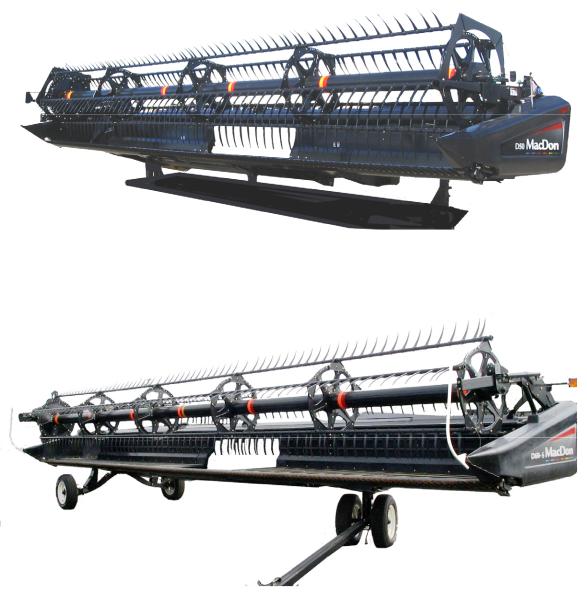
D50 HARVEST HEADER®
D60 HARVEST HEADER®
1 INTRODUCTION
This instructional manual contains operating and maintenance information on the MacDon D50/D60 Harvest Headers. They are designed to serve a dual function in your grain, hay, and specialty crop harvesting operation. Teamed with your self-propelled windrower power unit and optional hay conditioner, the D50 and D60 Harvest Headers will cut and lay crop into uniform fluffy windrows.
Windrowing allows starting the harvest earlier, protects the cop from wind damage, and gives you more flexibility in scheduling combine time.
CAREFULLY READ ALL THE MATERIAL PROVIDED BEFORE ATTEMPTING TO UNLOAD, ASSEMBLE, OR USE THE MACHINE.
Use this manual as your first source of information about the machine. If you follow the instructions given here, your Header will work well for many years.
If you require more detailed service information, a Service Manual is available from your MacDon Dealer.
Use the Table of Contents and the Index to guide you to specific areas. Study the Table of Contents to familiarize yourself with how the material is organized.
This manual must be used in conjunction with your Self-Propelled Windrower Operator's Manual.
Keep this manual handy for frequent reference and to pass on to new Operators or Owners.
A storage case for this manual is located inside the header left endshield.
Call your MacDon Dealer if you need assistance, information, or additional copies of this manual.
Published: October 2010
Form 169441 |
1 |
Revision B |
2 MODEL AND SERIAL NUMBER
NOTE: Right hand (RH) and Left-hand (LH) designations are determined from the Operator’s position, facing forward.
Record the Model Number, Serial Number and Model Year of the Header, and Slow Speed Transport/Stabilizer Wheel Option (if installed), on the lines below:
HEADER MODEL___________SERIAL NUMBER________________YEAR______
Serial Number Plate is located on the left hand endsheet, near the knife drive motor.
SLOW SPEED TRANSPORT/STABILIZER WHEEL OPTION
SERIAL NUMBER__________________YEAR______
Serial Number Plate is located on the left hand wheel pivot tube.
Form 169441 |
2 |
Revision B |
|
|
|
TABLE OF CONTENTS |
|
1 |
INTRODUCTION............................................................................................................................................ |
1 |
||
2 MODEL AND SERIAL NUMBER................................................................................................................... |
2 |
|||
3 |
SAFETY |
......................................................................................................................................................... |
6 |
|
|
3.1 |
SAFETY ALERT SYMBOL.................................................................................................................... |
6 |
|
|
3.2 |
SIGNAL ..................................................................................................................................WORDS |
6 |
|
|
3.3 |
SAFETY ....................................................................................................................................SIGNS |
6 |
|
|
3.3.1 |
................................................................................................................. |
Safety Sign Installation |
6 |
|
3.3.2 |
................................................................................................................... |
Safety Sign Locations |
7 |
|
3.4 |
GENERAL ............................................................................................................................SAFETY |
16 |
|
4 |
DEFINITIONS............................................................................................................................................... |
18 |
||
5 |
COMPONENT ................................................................................................................IDENTIFICATION |
19 |
||
6 |
SPECIFICATIONS ....................................................................................................................................... |
20 |
||
7 |
OPERATION ................................................................................................................................................ |
22 |
||
|
7.1 |
OWNER/OPERATOR .......................................................................................RESPONSIBILITIES |
22 |
|
|
7.2 |
OPERATIONAL ....................................................................................................................SAFETY |
22 |
|
|
7.3 |
HEADER .........................................................................................ATTACHMENT/DETACHMENT |
23 |
|
|
7.3.1 |
.................................................................................................................................. |
Attachment |
23 |
|
7.3.2 |
................................................................................................................................. |
Detachment |
24 |
|
7.4 |
BREAK ............................................................................................................................-IN PERIOD |
26 |
|
|
7.5 |
PRE .......................................................................................................................-SEASON CHECK |
26 |
|
|
7.6 |
DAILY .................................................................................................................START-UP CHECK |
27 |
|
|
7.7 |
SHUTDOWN ...............................................................................................................PROCEDURE |
27 |
|
|
7.8 |
HEADER ........................................................................................................................CONTROLS |
28 |
|
|
7.9 |
HEADER ...........................................................................................LIFT CYLINDER LOCK-OUTS |
28 |
|
|
7.10 |
REEL .....................................................................................................................................PROPS |
29 |
|
|
7.11 |
HEADER ...............................................................................................................................SET-UP |
30 |
|
|
7.12 |
HEADER ..................................................................................................OPERATING VARIABLES |
34 |
|
|
7.12.1 ............................................................................................................................. |
Cutting Height |
34 |
|
|
7.12.2 ............................................................................................................................... |
Header Float |
36 |
|
|
7.12.3 .............................................................................................................................. |
Header Angle |
37 |
|
|
7.12.4 ................................................................................................................................. |
Reel Speed |
38 |
|
|
7.12.5 ............................................................................................................................. |
Ground Speed |
39 |
|
|
7.12.6 .............................................................................................................................. |
Draper Speed |
40 |
|
|
7.12.7 ................................................................................................................................. |
Knife Speed |
40 |
|
|
7.12.8 ................................................................................................................................. |
Reel Height |
43 |
|
|
7.12.9 ................................................................................................................. |
Reel Fore - Aft Position |
43 |
|
|
7.12.10 ............................................................................................................................ |
Reel Tine Pitch |
48 |
|
|
7.12.11 .............................................................................................................. |
Crop Dividers and Rods |
50 |
|
|
7.13 |
DELIVERY ..................................................................................................OPENING/DECK SHIFT |
53 |
|
|
7.13.1 ............................................................................................................... |
Delivery Opening - D60 |
53 |
|
|
7.13.2 ............................................................................................................... |
Delivery Opening - D50 |
54 |
|
|
7.14 |
DOUBLE ....................................................................................................................WINDROWING |
55 |
|
|
7.14.1 .................................................................................................................... |
Hydraulic Deck Shift |
55 |
|
|
7.14.2 ....................................................................................................................... |
Manual Deck Shift |
55 |
|
|
7.15 |
WINDROW .............................................................................................................................TYPES |
57 |
|
|
7.16 |
HAYING ......................................................................................................................................TIPS |
58 |
|
|
7.16.1 .......................................................................................................................................... |
Curing |
58 |
|
|
7.16.2 .......................................................................................................................... |
Topsoil Moisture |
58 |
|
|
7.16.3 ........................................................................................................... |
Weather And Topography |
58 |
|
|
7.16.4 ................................................................................................................ |
Windrow Configuration |
58 |
|
|
7.16.5 ..................................................................................................................... |
Driving on Windrow |
58 |
|
|
7.16.6 .................................................................................................................... |
Raking And Tedding |
58 |
|
|
7.16.7 ............................................................................................................. |
Chemical Drying Agents |
59 |
|
|
7.17 |
DRAPER ....................................................................................................................DEFLECTORS |
60 |
|
|
7.17.1 ............................................................................................................... |
Deflector Replacement |
60 |
|
Form 169441 |
3 |
Revision B |
|
|
TABLE OF CONTENTS |
|
7.17.2 |
Deflector Rework ......................................................................................................................... |
60 |
|
7.18 |
HEADER LEVELLING ......................................................................................................................... |
61 |
|
7.19 |
UNPLUGGING CUTTERBAR ............................................................................................................. |
61 |
|
7.20 |
UPPER CROSS AUGER..................................................................................................................... |
62 |
|
7.21 |
TRANSPORTING HEADER ................................................................................................................ |
63 |
|
7.21.1 |
On The Windrower ...................................................................................................................... |
63 |
|
7.21.2 |
Towing ......................................................................................................................................... |
63 |
|
7.21.3 |
Converting from Transport to Field Position................................................................................ |
64 |
|
7.21.4 |
Converting from Field to Transport Position................................................................................ |
69 |
|
7.22 |
STORAGE ........................................................................................................................................... |
71 |
|
8 MAINTENANCE AND SERVICING.............................................................................................................. |
72 |
||
8.1 |
PREPARATION FOR SERVICING ..................................................................................................... |
72 |
|
8.2 |
RECOMMENDED SAFETY PROCEDURES ...................................................................................... |
72 |
|
8.3 |
MAINTENANCE SPECIFICATIONS ................................................................................................... |
73 |
|
8.3.1 |
|
Recommended Torques.............................................................................................................. |
73 |
8.3.2 |
|
Roller Chain Installation............................................................................................................... |
75 |
8.3.3 |
|
Sealed Bearing Installation.......................................................................................................... |
75 |
8.3.4 |
|
Recommended Fluids and Lubricants......................................................................................... |
76 |
8.3.5 |
|
Conversion Chart......................................................................................................................... |
76 |
8.4 |
ENDSHIELDS...................................................................................................................................... |
77 |
|
8.4.1 |
|
Hinged ......................................................................................................................................... |
77 |
8.4.2 |
|
Non-Hinged ................................................................................................................................. |
79 |
8.5 |
LUBRICATION..................................................................................................................................... |
80 |
|
8.5.1 |
|
Greasing Procedure .................................................................................................................... |
80 |
8.5.2 |
|
Lubrication Points ........................................................................................................................ |
80 |
8.5.3 |
|
Oiling Requirements .................................................................................................................... |
86 |
8.5.4 |
|
Hoses and Lines.......................................................................................................................... |
87 |
8.5.5 |
|
Hydraulic Schematics .................................................................................................................. |
88 |
8.6 |
ELECTRICAL....................................................................................................................................... |
92 |
|
8.7 |
SICKLE AND SICKLE DRIVE ............................................................................................................. |
93 |
|
8.7.1 |
|
Sickle Sections ............................................................................................................................ |
93 |
8.7.2 |
|
Sickle Removal............................................................................................................................ |
94 |
8.7.3 |
|
Sickle Head Bearing Replacement.............................................................................................. |
94 |
8.7.4 |
|
Sickle Installation......................................................................................................................... |
95 |
8.7.5 |
|
Spare Sickle (Single Knife Headers) ........................................................................................... |
95 |
8.7.6 |
|
Sickle Guards .............................................................................................................................. |
96 |
8.7.7 |
|
Sickle Hold-Downs ...................................................................................................................... |
99 |
8.7.8 |
|
Sickle Drive Belts - Non-Timed Drive ........................................................................................ |
100 |
8.7.9 |
|
Sickle Drive Belts - Timed Drive................................................................................................ |
101 |
8.7.10 |
Wobble Box ............................................................................................................................... |
106 |
|
8.8 |
DRAPERS ......................................................................................................................................... |
109 |
|
8.8.1 |
|
Draper Tension Adjustment....................................................................................................... |
109 |
8.8.2 |
|
Replacing Split Draper............................................................................................................... |
110 |
8.8.3 |
|
Replacing Endless Draper......................................................................................................... |
111 |
8.8.4 |
|
Draper Alignment....................................................................................................................... |
113 |
8.8.5 |
|
Draper Roller Maintenance ....................................................................................................... |
114 |
8.8.6 |
|
Deck Height ............................................................................................................................... |
117 |
8.9 |
REEL AND REEL DRIVE .................................................................................................................. |
118 |
|
8.9.1 |
|
Reel Clearance to Cutterbar...................................................................................................... |
118 |
8.9.2 |
|
Reel Frown Adjustment ............................................................................................................. |
119 |
8.9.3 |
|
Reel Centering........................................................................................................................... |
120 |
8.9.4 |
|
Reel Drive Chain - D60.............................................................................................................. |
121 |
8.9.5 |
|
Reel Drive Chain - D50.............................................................................................................. |
125 |
8.9.6 |
|
Reel Drive Sprocket - D60......................................................................................................... |
126 |
8.9.7 |
|
Reel Drive Sprocket - D50......................................................................................................... |
127 |
8.9.8 |
|
Reel Drive U-Joint - D60............................................................................................................ |
128 |
8.9.9 |
|
Reel Drive Motor - D60.............................................................................................................. |
129 |
8.9.10 |
Reel Drive Motor - D50.............................................................................................................. |
130 |
|
Form 169441 |
4 |
Revision B |
|
|
|
TABLE OF CONTENTS |
|
|
8.9.11 |
Reel Speed Sensor................................................................................................................... |
131 |
|
|
8.9.12 |
Reel Tines ................................................................................................................................. |
132 |
|
|
8.9.13 |
Tine Tube Bushings .................................................................................................................. |
134 |
|
|
8.10 |
TRANSPORT SYSTEM .................................................................................................................... |
138 |
|
|
8.10.1 |
Wheel Bolt Torque .................................................................................................................... |
138 |
|
|
8.10.2 |
Axle Bolts .................................................................................................................................. |
138 |
|
|
8.10.3 |
Tire Inflation .............................................................................................................................. |
138 |
|
|
8.11 |
MAINTENANCE SCHEDULE ........................................................................................................... |
139 |
|
|
8.11.1 |
Break-In Inspections ................................................................................................................. |
139 |
|
|
8.11.2 |
Interval Maintenance................................................................................................................. |
140 |
|
|
8.11.3 |
Maintenance Record................................................................................................................. |
141 |
|
9 |
TROUBLESHOOTING............................................................................................................................... |
142 |
||
|
9.1 |
CROP LOSS AT CUTTERBAR......................................................................................................... |
142 |
|
|
9.2 |
CUTTING ACTION AND SICKLE COMPONENTS .......................................................................... |
143 |
|
|
9.3 |
REEL DELIVERY .............................................................................................................................. |
145 |
|
|
9.4 |
HEADER AND DRAPERS ................................................................................................................ |
147 |
|
|
9.5 |
CUTTING EDIBLE BEANS ............................................................................................................... |
148 |
|
|
9.6 |
WINDROW FORMATION ................................................................................................................. |
151 |
|
10 |
OPTIONS AND ATTACHMENTS.............................................................................................................. |
152 |
||
|
10.1 |
CUTTERBAR POLY.......................................................................................................................... |
152 |
|
|
10.2 |
ADJUSTABLE SKID SHOES WITH POLY COVER ......................................................................... |
152 |
|
|
10.3 |
STUB GUARD CONVERSION KIT................................................................................................... |
152 |
|
|
10.4 |
STABILIZER WHEELS ..................................................................................................................... |
152 |
|
|
10.5 |
STABILIZER/TRANSPORT WHEELS .............................................................................................. |
152 |
|
|
10.6 |
LODGED CROP REEL FINGER KIT................................................................................................ |
153 |
|
|
10.7 |
VERTICAL KNIFE MOUNTS ............................................................................................................ |
153 |
|
|
10.8 |
UPPER CROSS AUGER KIT............................................................................................................ |
153 |
|
|
10.9 |
REEL ENDSHIELD KIT..................................................................................................................... |
153 |
|
|
10.10 |
DOUBLE DRAPER DRIVE ............................................................................................................... |
153 |
|
|
10.11 |
DRAPER EXTENSION KIT............................................................................................................... |
154 |
|
|
10.12 |
RICE DIVIDER KIT ........................................................................................................................... |
154 |
|
|
10.13 |
KNIFE HEAD SHIELD....................................................................................................................... |
154 |
|
|
10.14 |
SWATH FORMING RODS................................................................................................................ |
154 |
|
|
10.15 |
HYDRAULIC DECK SHIFT ............................................................................................................... |
154 |
|
|
10.16 |
DOUBLE WINDROW ATTACHMENT .............................................................................................. |
154 |
|
|
10.17 |
HAY CONDITIONER......................................................................................................................... |
155 |
|
|
10.18 |
ROCK RETARDER KIT .................................................................................................................... |
155 |
|
|
10.19 |
HYDRAULIC REEL FORE-AFT POSITIONER................................................................................. |
155 |
|
11 |
UNLOADING AND ASSEMBLY................................................................................................................ |
156 |
||
INDEX ................................................................................................................................................................ |
|
. |
157 |
|
Form 169441 |
5 |
Revision B |

SECTION 3. SAFETY
3 SAFETY
3.1SAFETY ALERT SYMBOL
This safety alert symbol indicates important safety messages in this manual and on safety signs on the machine.
This symbol means:
•ATTENTION!
•BECOME ALERT!
•YOUR SAFETY IS INVOLVED!
Carefully read and follow the safety message accompanying this symbol.
WHY IS SAFETY IMPORTANT TO YOU?
•ACCIDENTS DISABLE AND KILL.
•ACCIDENTS COST.
•ACCIDENTS CAN BE AVOIDED.
3.2SIGNAL WORDS
Note the use of the signal words DANGER, WARNING, and CAUTION with safety messages. The appropriate signal word for each message has been selected using the following guidelines:
DANGER
Indicates an imminently hazardous situation that if not avoided, will result in death or serious injury.
WARNING
Indicates a potentially hazardous situation that if not avoided, could result in death or serious injury. It is also used to alert against unsafe practices.
CAUTION
Indicates a potentially hazardous situation that if not avoided, may result in minor or moderate injury. It is also used as a reminder of good safety practices.
3.3SAFETY SIGNS
•The safety signs appear on the header at the locations shown in the Section 3.3.2.
•Keep safety signs clean and legible at all times.
•Replace safety signs that are missing or become illegible.
•If original parts on which a safety sign was installed are replaced, be sure the repair part also bears the current safety sign.
•Safety signs are available from your MacDon Dealer Parts Department.
3.3.1SAFETY SIGN INSTALLATION
a.Be sure the installation area is clean and dry.
b.Decide on the exact location before you remove the decal backing paper.
c.Remove the smaller portion of the split backing paper.
d.Place the decal in position and slowly peel back the remaining paper, smoothing the decal as it is applied.
e.Small air pockets can be smoothed out or pricked with a pin.
Form 169441 |
6 |
Revision B |
SECTION 3. SAFETY
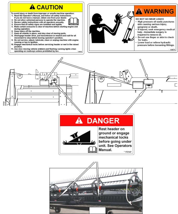
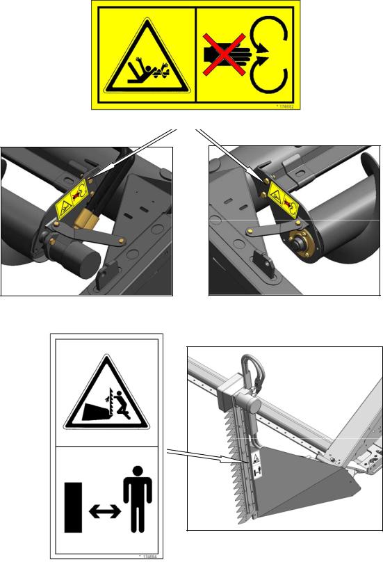
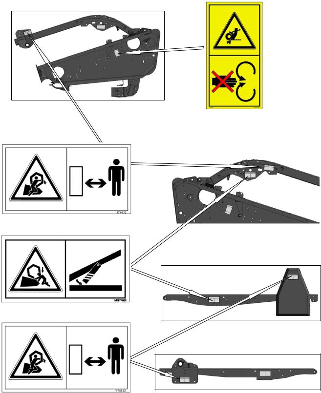
3.3.2SAFETY SIGN LOCATIONS
3.3.2.13-Panel Safety Signs - North America
|
|
BACK TUBE #134070 |
BACK TUBE - BOTH ENDS #109843 |
|
|
|
|
|
|
|
|
|
|
|
|
|
|
|
|
|
|
|
|
|
|
|
|
|
|
|
D60 20 FT |
|
|
D60 15 FT |
|
|
|
|
|
|
|
|
|
|
|
|
|
|
|
|
|
|
|
|
|
|
|
|
|
|
BACK TUBE & DECKS - BOTH ENDS #172147
ALL
Form 169441 |
7 |
Revision B |

SECTION 3. SAFETY
3-Panel Safety Signs - North America (Cont’d)
D50, D60 - 25, 30, 35, 40, FT
BACK TUBE #134070 |
|
BACK TUBE - BOTH ENDS #109843 |
|
|
|
|
|
|
|
|
|
|
|
|
|
|
|
D50, D60 - 30, 35, 40 FT |
|
|
|
|
|
|
|
|
D60 25 FT |
|
|
|
|
|
|
|
|
|
|
|
|
|
|
BACK TUBE BOTH ENDS BACK TUBE - DOUBLE REEL ONLY #172147
#42122
Form 169441 |
8 |
Revision B |
SECTION 3. SAFETY
3-Panel Safety Signs - North America (Cont’d)
ALL
LH & RH REEL ARMS #174633
LH & RH REEL ARM #42122
REEL ARMS #174633
BOTH ENDS - DOUBLE KNIFE LEFT END - SINGLE KNIFE #142909
D60
D50
D50
Form 169441 |
9 |
Revision B |
SECTION 3. SAFETY
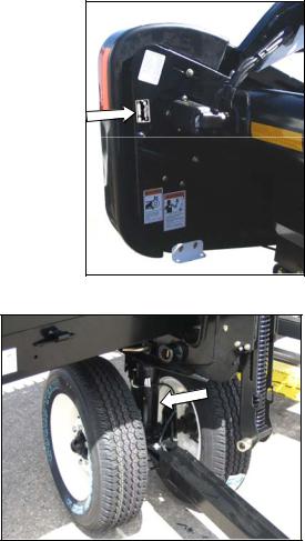
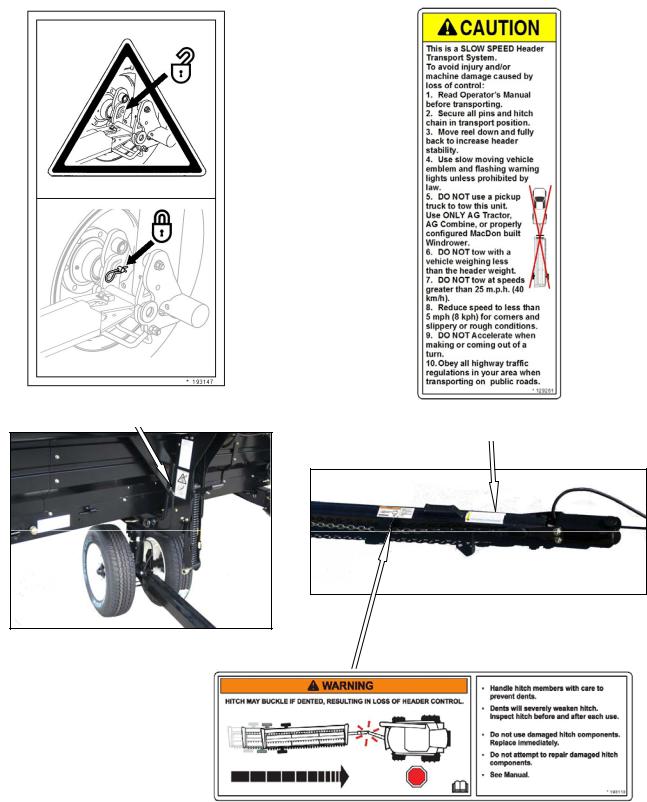
3.3.2.22-Panel Safety Signs - North America and Export
FRONT TRANSPORT LEG
#193147 TOW-BAR #129261
D50/D60 - 25, 30, 35 FT, D60 - 40 FT
TOW-BAR #193113
Form 169441 |
10 |
Revision B |
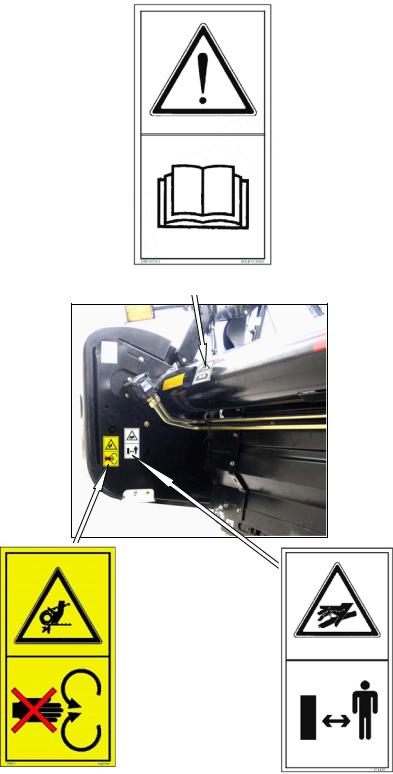
SECTION 3. SAFETY
2-Panel Safety Signs - North America and Export (Cont’d)
UPPER CROSS AUGER #174682
LH & RH VERTICAL KNIFE #174684
Form 169441 |
11 |
Revision B |
SECTION 3. SAFETY
2-Panel Safety Signs - North America and Export (Cont’d)
BOTH ENDS #113482
BOTH ENDS - DOUBLE KNIFE
LEFT END - SINGLE KNIFE BOTH ENDS #174436 #184371
Form 169441 |
12 |
Revision B |
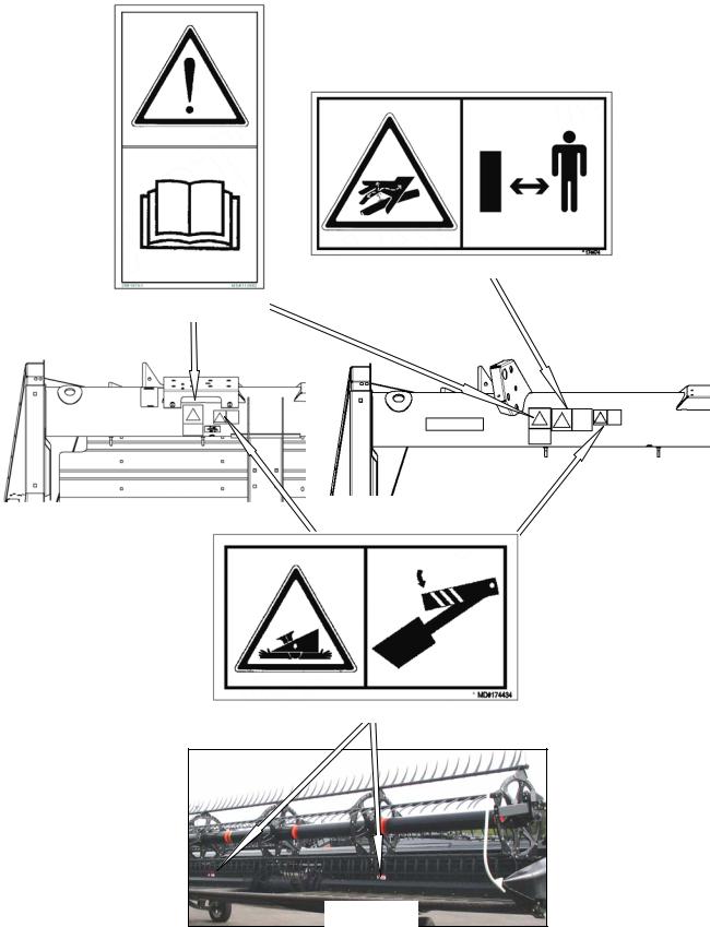
SECTION 3. SAFETY
3.3.2.32-Panel Safety Signs - Export
BACKTUBE #174474
BOTH ENDS #113482
|
|
|
|
D60 20 FT |
|
D60 15 FT |
|
||
|
|
|
|
|
BACKTUBE & DECKS #174434
ALL
Form 169441 |
13 |
Revision B |
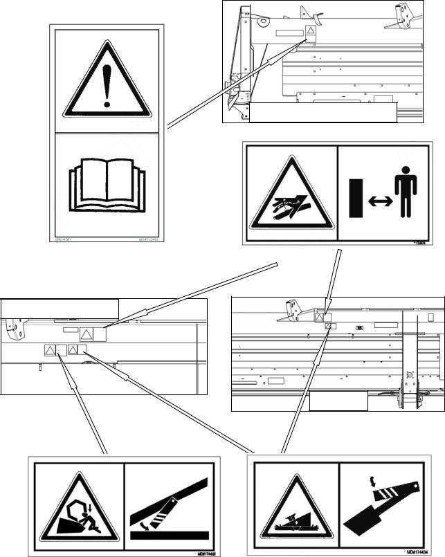
SECTION 3. SAFETY
2-Panel Safety Signs – Export (Cont’d)
D50, D60 - 25, 30, 35, 40 FT
BOTH ENDS #113482 |
|
|
|
BACK TUBE - BOTH ENDS |
|||
|
|
||
|
|
#174474 |
|
|
|
||
|
|
|
D50, D60 - 30, 35, 40 FT
D60 25 FT
BACK TUBE - DOUBLE REEL ONLY |
BACK TUBE - BOTH ENDS |
#174432 |
#174434 |
|
|
Form 169441 |
14 |
Revision B |
SECTION 3. SAFETY
2-Panel Safety Signs - Export (Cont’d)
ALL
BOTH ENDS - DOUBLE KNIFE LEFT END - SINGLE KNIFE #184371
|
|
|
|
REEL ARMS |
|
D60 |
|
|
|
|
|
#174632 |
|
|
|
LH & RH REEL ARM |
D50 |
#174432 |
D50
REEL ARMS #174632
Form 169441 |
15 |
Revision B |

SECTION 3. SAFETY
3.4GENERAL SAFETY
CAUTION
•The following are general farm safety precautions that should be part of your operating procedure for all types of machinery.
•Protect yourself. When assembling, operating and servicing machinery, wear all the protective clothing and personal safety devices that COULD be necessary for the job at hand. Don't take chances.
•You may need:
•Provide a first-aid kit for use in case of emergencies.
•Keep a fire extinguisher on the machine. Be sure the extinguisher is properly maintained and be familiar with its proper use.
•Keep young children away from machinery at all times.
•a hard hat.
•protective shoes with slip resistant soles.
•protective glasses or goggles.
•heavy gloves.
•wet weather gear.
•respirator or filter mask.
A
B
•hearing protection. Be aware that prolonged exposure to loud noise can cause impairment or loss of hearing. Wearing a suitable hearing protective device such as ear muffs
(A) or ear plugs (B) protects against objectionable or loud noises.
•Be aware that accidents often happen when the Operator is tired or in a hurry to get finished. Take the time to consider the safest way. Never ignore warning signs of fatigue.
•Wear close-fitting clothing and cover long hair. Never wear dangling items such as scarves or bracelets.
•Keep hands, feet, clothing and hair away from moving parts. Never attempt to clear obstructions or objects from a machine while the engine is running.
•Keep all shields in place. Never alter or remove safety equipment. Make sure driveline guards can rotate independently of the shaft and can telescope freely.
Form 169441 |
16 |
Revision B |

SECTION 3. SAFETY
•Use only service and repair parts made or approved by the equipment manufacturer. Substituted parts may not meet strength, design, or safety requirements.
•Do not modify the machine. Unauthorized modifications may impair the function and/or safety and affect machine life.
•Stop engine, and remove key from ignition before leaving Operator's seat for any reason. A child or even a pet could engage an idling machine.
•Keep the area used for servicing machinery clean and dry. Wet or oily floors are slippery. Wet spots can be dangerous when working with electrical equipment. Be sure all electrical outlets and tools are properly grounded.
•Use adequate light for the job at hand.
•Keep machinery clean. Straw and chaff on a hot engine are a fire hazard. Do not allow oil or grease to accumulate on service platforms, ladders or controls. Clean machines before storage.
•Never use gasoline, naphtha or any volatile material for cleaning purposes. These materials may be toxic and/or flammable.
•When storing machinery, cover sharp or extending components to prevent injury from accidental contact.
Form 169441 |
17 |
Revision B |
SECTION 4. DEFINITIONS
4 DEFINITIONS
TERM |
DEFINITION |
|
|
API |
American Petroleum Institute |
|
|
ASTM |
American Society of Testing And Materials |
|
|
Cab-Forward |
Windrower operation with the operator and cab facing in the direction of travel |
|
|
CDM |
Cab Display Module |
|
|
DWA |
Double Windrow Attachment |
|
|
Engine-Forward |
Windrower operation with the Operator and engine facing in the direction of travel |
|
|
ISC |
Integrated Speed Control |
|
|
N-DETENT |
The slot opposite the neutral position on operator’s console |
|
|
rpm |
Revolutions per minute |
|
|
SAE |
Society Of Automotive Engineers |
|
|
WCM |
Windrower Control Module |
|
|
Windrower |
Windrower with header attached |
|
|
Windrower Tractor |
Power unit only. (Windrower without the header attached) |
|
|
Form 169441 |
18 |
Revision B |
SECTION 5. COMPONENT IDENTIFICATION
5 COMPONENT IDENTIFICATION
|
|
|
|
|
|
CENTER REEL ARM |
REEL CAM |
|
PICK-UP REEL TINES |
|
DRAPERS |
|
|
|
|
|
PROP HANDLE |
|||
|
|
|
|
|
|
|
|
|
|
|
|
|
|
HYDRAULIC CONNECTIONS
REEL PROP
REEL FORE-AFT CYLINDER |
|
REEL ENDSHIELDS |
TRANSPORT LIGHT |
|
CROP DIVIDER ROD
SKID SHOE
CROP DIVIDER |
WOBBLE BOX |
REEL LIFT CYLINDER |
REMOVEABLE ENDSHIELD |
Form 169441 |
19 |
Revision B |
SECTION 6. SPECIFICATIONS
6 SPECIFICATIONS
|
|
|
|
HEADER MODEL |
D60 |
|
|
|
D50/D60 |
|
D60 |
||
|
|
|
|
HEADER SIZE |
15 FT. |
|
20 FT. |
25 FT. |
30 FT. |
35 FT. |
40 FT. |
||
OVERALL |
|
|
|
|
|
|
|
|
|
|
|
|
|
|
|
|
|
|
|
|
|
|
|
|
|
|
|
|
|
|
|
Transport (Reel Full |
|
|
|
96 (2438) |
|
|
|||
Width |
|
|
Aft) With CA20 Adapter |
|
|
|
|
|
|||||
|
|
|
|
|
|
|
|
|
|||||
(Inches (mm)) |
|
|
|
|
Field |
|
|
255.1 |
315.1 |
375.1 |
435.1 |
495.1 |
|
|
|
|
|
|
|
|
|||||||
|
|
|
|
|
|
|
(6479) |
(8003) |
(9527) |
(11051) |
(12575) |
||
|
|
|
|
|
|
|
|
||||||
|
|
|
|
|
|
|
|
|
|
|
|
|
|
Length |
|
Transport (with Tow Pole) |
Not Applicable |
|
505.7 |
547.5 |
601.5 |
||||||
(Inches (mm)) |
|
|
(12845) |
(13907) |
(15278) |
||||||||
|
|
|
|
|
|
|
|
|
|||||
|
|
|
|
|
|
|
|
|
|
|
|
||
Height - Transport |
|
|
|
|
|
|
97 in. (2464 mm) |
|
|
||||
|
|
|
|
|
|
|
|
|
|
|
|
|
|
|
|
|
|
|
D50 |
Not Applicable |
3500 (1589) |
4150 (1884) |
4700 (2134) |
Not |
|||
Estimated Weight Range |
Applicable |
||||||||||||
|
|
|
|
|
|
|
|||||||
|
|
|
|
|
|
|
|
||||||
Base Header |
(lb (kg)) |
D60 |
3000 |
|
3400 |
3500 - 4100 |
4200 - 5100 |
4700 - 5700 |
5400 - 5800 |
||||
|
|
|
|
|
(1362) |
|
(1544) |
(1589 - 1861) |
(1907-2315) |
(2134 - 2588) |
(2451 - 2633) |
||
|
|
|
|
|
|
|
|||||||
|
|
|
|
|
|
|
|
|
|
|
|
|
|
CUTTERBAR |
|
|
|
|
|
|
|
|
|
|
|
|
|
Width Inches (mm) |
|
|
|
180 |
|
240 |
300 |
360 |
420 |
480 |
|||
|
|
|
(4572) |
|
(6096) |
(7620) |
(9144) |
(10668) |
(12192) |
||||
|
|
|
|
|
|
|
|||||||
|
|
|
|
|
|
|
|
|
|
|
|
||
|
|
|
|
Shortest Center-Link |
1.3 in. (32 mm) below ground - |
0.8 in. (20 mm) below ground - |
|||||||
Header Cutting |
|
52.3 in. (1328 mm) above |
52.8 in. (1340 mm) above |
||||||||||
|
|
|
|||||||||||
|
|
|
|
|
|
|
|
|
|
||||
Height |
|
|
|
Longest Center-Link |
4.6 in. (117 mm) below ground - |
4.1 in. (105 mm) below ground - |
|||||||
|
|
|
|
||||||||||
|
|
|
|
46.9 in. (1192 mm) above |
47.4 in. (1204 mm) above |
||||||||
|
|
|
|
|
|
||||||||
|
|
|
|
|
|
|
|||||||
Guard Angle (Cutterbar on Ground) |
7.5° - 17.0° |
|
|
2.5° - 12.0° |
|
||||||||
|
|
|
|
|
|
|
|
|
|
|
|
|
|
SICKLE |
|
|
|
|
|
|
|
|
|
|
|
|
|
|
|
|
|
|
|
|
|
|
|||||
|
|
|
|
|
SK |
Not Applicable |
|
Hydraulic Motor / ‘C’ Belt/Heavy Duty (MD) Wobble Box |
|||||
|
|
|
|
|
|
|
|
|
|
|
|
|
|
|
|
|
|
|
|
|
|
|
|
|
|
Two |
|
|
|
|
|
|
|
|
|
|
|
|
|
Hydraulic |
|
Drive Type |
|
|
|
|
|
|
|
|
|
|
|
Motors To |
|
|
|
|
DK (Except D50) |
Hydraulic Motor / Two ‘B’ Timing Belts / |
|
"C" Belts, |
|||||||
|
|
|
|
|
|||||||||
|
|
|
|
|
Two Heavy Duty (MD) Wobble Boxes |
|
Untimed To |
||||||
|
|
|
|
|
|
|
|
||||||
|
|
|
|
|
|
|
|
|
|
|
|
Heavy Duty |
|
|
|
|
|
|
|
|
|
|
|
|
|
(MD) Wobble |
|
|
|
|
|
|
|
|
|
|
|
|
|
Boxes |
|
|
|
|
|
|
|
|
|
|
|
|
|||
Sickle Speed |
|
|
|
|
SK |
Not Applicable |
|
1200 - 1500 |
1200 - 1400 |
1100 - 1300 |
1050 - 1200 |
||
|
|
|
|
|
|
|
|
|
|
|
|
||
(Strokes Per Minute) |
|
DK (Except D50) |
1500 - 1900 |
|
1400 - 1700 |
1200 - 1600 |
1200 - 1500 |
1100 - 1400 |
|||||
|
|
|
|
|
|||||||||
|
|
|
|
|
|
|
|
|
|
|
|
|
|
Stroke |
|
|
|
|
|
|
|
|
3 in. (76 mm) |
|
|
||
|
|
|
|
|
|
|
|
|
|
|
|
|
|
Sections - |
|
|
|
|
|
|
|
|
|
|
|
|
|
Over-Serrated and |
|
Cut-Out or Solid |
|
14 |
|
9 / 14 |
9 |
||||||
Bolted |
|
|
|
|
|
||||||||
|
|
|
|
|
|
|
|
|
|
|
|
||
(serrations/inch) |
|
|
|
|
|
|
|
|
|
|
|||
|
|
|
|
|
|
|
|
|
|
|
|
||
|
|
|
|
|
D50 |
Not Applicable |
Pointed / Case Hardened / |
Not |
|||||
|
|
|
|
Pointed |
Sheet Metal / Adjuster Bolt |
Applicable |
|||||||
|
|
|
|
|
|
|
|
||||||
|
|
|
|
|
|
|
|
|
|
|
|
||
Guards and |
|
|
|
D60 |
Case Hardened or Double Heat Treated / Sheet Metal / Adjuster Bolt |
||||||||
|
|
|
|
||||||||||
|
|
|
|
|
|
|
|
|
|
|
|
||
Hold-Downs |
|
|
|
Stub (Except D50) |
|
|
|
Sheet Metal |
|
|
|
||
|
|
|
|
|
|
|
|
|
|
||||
|
|
|
|
Sheet Metal HD |
or |
|
Not Applicable |
|
|||||
|
|
|
|
|
|
|
|
|
Forged HD |
|
|
|
|
|
|
|
|
|
|
|
|
|
|
|
|
|
|
Form 169441 |
20 |
Revision B |

SECTION 6. SPECIFICATIONS
|
HEADER MODEL |
D60 |
|
|
|
|
D50/D60 |
|
|
D60 |
||
|
HEADER SIZE |
15 FT. |
20 FT. |
|
25 FT. |
|
30 FT. |
|
35 FT. |
|
40 FT. |
|
CONVEYOR AND DECKS |
|
|
|
|
|
|
|
|
|
|
|
|
|
|
|
|
|
|
|
|
|
|
|||
Draper Drive |
|
|
|
|
|
Hydraulic |
|
|
|
|||
|
|
|
|
|
|
|
|
|
|
|||
Draper Width |
|
|
|
|
|
41.6 in. |
|
|
|
|||
|
|
|
|
|
(1057 mm) |
|
|
|
||||
|
|
|
|
|
|
|
|
|
||||
|
|
|
|
|
|
|
|
|
|
|||
Draper Speed |
|
|
|
|
|
0 - 742 ft/min |
|
|
|
|||
|
|
|
|
|
(225 m/min) |
|
|
|
||||
|
|
|
|
|
|
|
|
|
||||
|
|
|
|
|
|
|
|
|
|
|
|
|
|
|
D50 |
Not Applicable |
|
|
|
67.3 - 75.6 in. |
|
|
Not |
||
|
|
|
|
(1710 - 1920 mm) |
|
|
Applicable |
|||||
|
|
|
|
|
|
|
|
|
||||
Delivery Opening |
|
D60 |
60.61 - 69.7 in. |
|
|
|
|
67.1 - 76.7 in. |
|
|
|
|
|
(1540 - 1770 mm) |
|
|
|
|
(1720 - 1950 mm) |
|
|||||
|
|
|
|
|
|
|
|
|||||
|
|
|
|
|
|
37.2 - 41.7 in. |
|
|
|
|||
|
|
Height |
|
|
|
|
|
|
||||
|
|
|
|
|
(945 - 1058 mm) |
|
|
|
||||
|
|
|
|
|
|
|
|
|
||||
|
|
|
|
|
|
|
|
|
|
|
|
|
Draper Angle |
|
D50 & D60 |
|
|
13.0° - 18.4° |
|
|
|
|
|||
(Cutterbar on Ground) |
|
|
|
|
|
|
|
|||||
|
|
|
|
|
|
|
|
|
|
|
|
|
|
|
|
|
|
|
|
|
|
|
|
|
|
REEL |
|
|
|
|
|
|
|
|
|
|
|
|
|
|
|
|
|
|
|
||||||
Drive |
|
|
|
Hydraulic From Windrower Hydraulic Oil Supply |
|
|||||||
|
|
|
|
|
|
|
|
|
|
|||
Speed |
|
|
|
|
|
0 - 62 rpm |
|
|
|
|||
|
|
|
|
|
|
|
|
|
|
|
||
Quantity of Tine Tubes |
|
|
6/9 |
|
|
5 - D50, |
6 / 9 - D60 |
|
5 / 6 |
|
5 |
|
|
|
|
|
|
|
|
|
|
|
|
||
Effective Reel Diameter |
|
|
|
|
|
65 in. |
|
|
|
|||
|
|
|
|
|
(1650 mm) |
|
|
|
||||
|
|
|
|
|
|
|
|
|
||||
|
|
|
|
|
|
|
|
|
|
|||
Finger Tip Radius Range |
|
|
|
30.2 - 31.5 in. |
|
|
|
|||||
|
|
|
(766 - 800 mm) |
|
|
|
||||||
|
|
|
|
|
|
|
|
|
||||
|
|
|
|
|
|
|
|
|
|
|
||
Finger Type |
|
Plastic |
- |
|
|
|
|
Standard |
|
|||
|
|
|
|
|
|
|
|
|
|
|
|
|
Heavy Duty Plastic |
Standard |
|
|
|
|
Optional D60 |
|
|
- |
|||
|
|
|
|
|
|
|
||||||
|
|
|
|
|
|
|
|
|
|
|||
Finger Spacing |
|
|
|
|
|
6.0 in. |
|
|
|
|||
|
|
|
|
|
(152.4 mm) |
|
|
|
||||
|
|
|
|
|
|
|
|
|
||||
|
|
|
|
|
|
|
|
|
|
|
||
UPPER CROSS AUGER (Optional) |
|
|
|
|
|
|
|
|
|
|
||
|
|
|
|
|
|
|
|
|
|
|||
Outside Diameter |
|
|
|
|
|
12 in. (305 mm) |
|
|
|
|||
|
|
|
|
|
|
|
|
|
|
|
||
Weight (lb (kg)) |
|
|
134 |
163 |
192 |
|
221 |
|
250 |
|
279 |
|
|
|
(61) |
(74) |
(87) |
|
(100) |
|
(113) |
|
(127) |
||
|
|
|
|
|
|
|||||||
|
|
|
|
|
|
|
|
|
|
|
||
STABILIZER WHEELS (Optional) |
|
|
|
|
|
|
|
|
|
|
||
|
|
|
|
|
|
|
|
|
|
|||
Size |
|
|
|
|
|
|
|
ST205 / 75R-15 |
|
|||
|
|
|
Not Applicable |
|
|
|
Load Range E - 80 psi (552 kPa) |
|||||
Pressure |
|
|
|
|
|
|||||||
|
|
|
|
|
Load Range D - 60 psi (415 kPa) |
|||||||
|
|
|
|
|
|
|
|
|||||
|
|
|
|
|
|
|
|
|
|
|
||
Weight |
|
|
|
|
|
|
|
|
200 lb (91 kg) |
|
||
|
|
|
|
|
|
|
|
|
|
|
|
|
NOTES: 1. Specifications and design are subject to change without notice, or obligation to revise previously sold units. 2. Weights do not include options.
Form 169441 |
21 |
Revision B |
SECTION 7. OPERATION
7 OPERATION
7.1OWNER/OPERATOR RESPONSIBILITIES
CAUTION
•It is your responsibility to read and understand this manual completely before operating the header. Contact your MacDon Dealer if an instruction is not clear to you.
•Follow all safety messages in the manual and on safety signs on the machine.
•Remember that YOU are the key to safety. Good safety practices protect you and the people around you.
•Before allowing anyone to operate the header, for however short a time or distance, make sure they have been instructed in its safe and proper use.
•Review the manual and all safety related items with all Operators annually.
•Be alert for other Operators not using recommended procedures or not following safety precautions. Correct these mistakes immediately, before an accident occurs.
•Do not modify the machine. Unauthorized modifications may impair the function and/or safety and affect machine life.
•The safety information given in this manual does not replace safety codes, insurance needs, or laws governing your area. Be sure your machine meets the standards set by these regulations.
7.2OPERATIONAL SAFETY
Follow these safety precautions:
CAUTION
•Follow all safety and operational instructions given in your Operator's Manuals. If you do not have a windrower manual, get one from your dealer and read it thoroughly.
•Never attempt to start the engine or operate the machine except from the windrower seat.
•Check the operation of all controls in a safe clear area before starting work.
•Do not allow riders on windrower.
•Never start or move the machine until you are sure all bystanders have cleared the area.
•Avoid travelling over loose fill, rocks, ditches or holes.
•Drive slowly through gates and doorways.
•When working on inclines, travel uphill or downhill when possible. Be sure to keep transmission in gear when travelling downhill.
•Never attempt to get on or off a moving machine.
•Do not leave Operator’s station while the engine is running.
•Stop engine, and remove key before adjusting or removing plugged material from the machine. A child or even a pet could engage the drive.
•Check for excessive vibration and unusual noises. If there is any indication of trouble, shut down and inspect the machine. Follow proper shutdown procedure. Refer to Section 7.7 SHUTDOWN PROCEDURE.
•Operate only in daylight or good artificial light.
Form 169441 |
22 |
Revision B |
SECTION 7. OPERATION
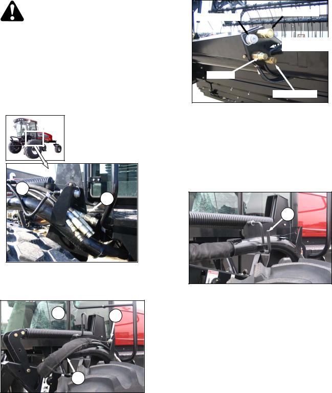
7.3HEADER ATTACHMENT/DETACHMENT
7.3.1ATTACHMENT
Refer to the M150/M200 or M205 Self-Propelled Windrower Operator’s Manual for procedures to mechanically attach the header to the selfpropelled windrower. Refer to the following procedures for electrical and hydraulic connections.
The header drive hydraulic hoses and electrical harness are located on the left cab-forward side of the tractor. The reel drive and control hoses are located on the right cab-forward side.
4.Move hose bundle (A) from tractor around hose support on header.
KNIFE DRIVE
ELECTRICAL
CASE DRAIN (DOUBLE KNIFE)
RETURN
DRAPER DRIVE
B
A
a.Connect header drive hydraulics (A) and electrical harness (B) to header as follows:
1. Check connectors, and clean if required.
C  D
D
5.Push hose connectors onto mating receptacle until collar on receptacle snaps into “lock” position.
6.Remove cover on electrical receptacle.
7.Push electrical connector onto receptacle, and turn collar on connector to lock it in place.
8.Attach cover to mating cover on tractor wiring harness.
C
9.Lower lever (C), and engage in “down” position.
(continued next page)
A
2.Disengage and rotate lever (C) counter clockwise to fully “up” position.
3.Remove cap (D) securing electrical connector to frame.
Form 169441 |
23 |
Revision B |
SECTION 7. OPERATION
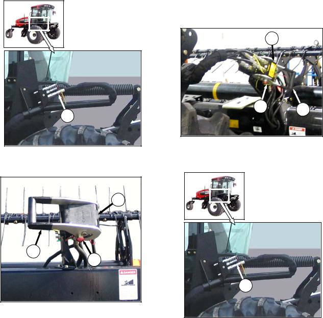
E
b.Connect reel hydraulics (E) as follows:
1. Check connectors, and clean if required.
F
H
G
2.Open cover (F) on header receptacle.
3.Push in lock button (G), and pull handle (H) to “half open” position.
4.Remove hose bundle with multi-coupler (E) from tractor, position onto header receptacle, and push handle (H) to engage pins on connector.
5.Push handle away from hoses until lock button (G) snaps out.
c.Raise and lower header and reel a few times to allow trapped air to pass back to the reservoir.
7.3.2DETACHMENT
a.Fully lower the reel.
b.Disconnect the reel hydraulics as follows:
E
G H
1.Push in lock button (G), and pull handle (H) to disengage multi-coupler (E) from header receptacle.
E
2.Route hose bundle back onto windrower, and store multi-coupler (E) on hose support.
3.Close cover (F) on header receptacle. (shown in previous column)
(continued next page)
Form 169441 |
24 |
Revision B |

SECTION 7. OPERATION
c.Disconnect the header drive hydraulics as follows:
C
1.Disengage and rotate lever (C) counter clockwise to fully up position.
2.Disconnect electrical connector from header.
3.Disconnect hoses from header as follows:
K
J 
i.Line up slot (J) in collar with pin (K) on connector.
ii.Push collar toward pin, and pull connector to disengage.
iii.Install caps on connectors and hose ends (if equipped).
A
D
C
4.Route hose bundle (A) back onto hose support on windrower.
5.Rotate lever (C), and lock in down position.
6.Install cap (D) on electrical connector.
d.Detach header from windrower. Refer to the M150/M200 or M205 Self-Propelled Windrower Operator’s Manual.
Form 169441 |
25 |
Revision B |

SECTION 7. OPERATION
7.4BREAK-IN PERIOD
a.After attaching header to windrower for the first time, operate the machine with reel drapers and sickle running slowly for 5 minutes, watching and listening FROM THE OPERATOR'S SEAT for binding or interfering parts.
NOTE
Reel and side drapers will not operate until oil flow fills the lines.
CAUTION
7.5PRE-SEASON CHECK
Perform the following the beginning of each operating season:
CAUTION
•Review the Operator's Manual to refresh your memory on safety and operating recommendations.
•Review all safety signs and other decals on the header and note hazard areas.
Before investigating an unusual sound or attempting to correct a problem, shut off engine, and remove key.
b.Perform the items specified in 8.11.1 Break-In Inspections.
NOTE
Until you become familiar with the sound and feel of your new header, be extra alert and attentive.
•Be sure all shields and guards are properly installed and secured. Never alter or remove safety equipment.
•Be sure you understand and have practiced safe use of all controls. Know the capacity and operating characteristics of the machine.
•Check the first aid kit and fire extinguisher. Know where they are and how to use them.
a.Adjust tension on drive belts. Refer to Sections 8.7.8 Sickle Drive Belts - Non-Timed Drive and 8.7.9 Sickle Drive Belts - Timed Drive.
b.Perform all annual maintenance. See Section 8.11 MAINTENANCE SCHEDULE.
Form 169441 |
26 |
Revision B |

SECTION 7. OPERATION
7.6DAILY START-UP CHECK
Do the following each day before start-up:
CAUTION
7.7SHUTDOWN PROCEDURE
CAUTION
Before leaving the windrower seat for any reason:
•Clear the area of other persons, pets etc. Keep children away from machinery. Walk around the machine to be sure no one is under, on or close to it.
•Wear close fitting clothing and protective shoes with slip resistant soles.
•Remove foreign objects from the machine and surrounding area.
•As well, carry with you any protective clothing and personal safety devices that COULD be necessary through the day. Don't take chances.
•You may need:
•Park on level ground if possible.
•Lower the header fully.
•Place all controls in NEUTRAL or PARK.
•Disengage header drive.
•Stop engine, and remove key from ignition.
•Wait for all movement to stop.
-a hard hat
-protective glasses or goggles
-heavy gloves
-respirator or filter mask
-wet weather gear
•Protect against noise. Wear a suitable hearing protective device such as ear muffs or ear plugs to protect against objectionable or uncomfortable loud noises.
a.Check the machine for leaks or any parts that are missing, broken, or not working correctly.
NOTE
Use proper procedure when searching for pressurized fluid leaks. Refer to Section 8.5.4 Hoses and Lines.
b.Clean all lights and reflective surfaces on the machine.
c.Perform all Daily maintenance. Refer to Section 8.11 MAINTENANCE SCHEDULE.
Form 169441 |
27 |
Revision B |

SECTION 7. OPERATION
7.8HEADER CONTROLS
CAUTION
Be sure all bystanders are clear of machine before starting engine or engaging any header drives.
See your Windrower Operator's Manual for identification of in-cab controls for:
•Header Drive Clutch
•Header Height
•Header Angle
•Ground Speed
•Reel Speed
•Reel Height
•Reel Fore-Aft Position
7.9HEADER LIFT CYLINDER LOCKOUTS
DANGER
To avoid bodily injury or death from fall of raised machine, always engage lift cylinder stops before going under header for any reason. See your Windrower Operator’s Manual for instructions for use and storage of header lift cylinder stops.
Form 169441 |
28 |
Revision B |
 Loading...