

Lumos GSX Solar Module System
Installation Manual
February 2016
Version 4
Page 1
Date Modified: Feb 10, 2016
File Name: 20160210_Rev004_GSX Installation Manual
Warnings and Safety Guidelines
Page 2
Date Modified: Feb 10, 2016
File Name: 20160210_Rev004_GSX Installation Manual
Installation, operation and maintenance of photovoltaic systems can be dangerous, and should be performed only by qualified persons. This manual should be
read and understood fully before attempting to install any Lumos GSX Module System components.
Installations must conform to all applicable building and/or electrical codes and regulations, both national and local. It is the installer’s responsibility to determine
and fulfill all necessary requirements, including obtaining permits and inspections, if necessary.
Installers should maintain a safe installation environment. All OSHA or equivalent guidelines should be followed. Protective headgear, eye protection, insulating
gloves, protective footwear and insulated tools are recommended. Do not attempt to install modules in windy or wet conditions. Do not install any photovoltaic
components where flammable gasses may be present.
Modules should be handled with care. Keep the modules in the original packaging as long as possible. Stack module boxes neatly and evenly. Do not drop the
module. Do not drop any objects on the module. Avoid bending the module. Do not use sharp tools or chemicals to clean the module, other than as specifically
directed by this manual, as this may damage the module. Do not attempt to drill any holes in any part of the module. Do not use the junction box as a handle.
Lumos GSX Modules should only be installed with Lumos approved racking. Lumos does not accept any responsibility for loss or damage as a result of
attempting to install GSX Modules with other mounting systems.
Approved suction cups may be used to handle the modules. However, Lumos does not accept any responsibility for damages related to the use of suction cups,
approved or otherwise. If utilizing suction cups to handle the modules, check that they are clean and free of dirt or debris. Ensure that the suction cup is fully
adhered to the module before attempting to move the module.
Modules are to be installed only on approved structures. It is the installer’s responsibility to certify that the structure upon which the modules are to be mounted
can handle the loads induced by the modules.
Photovoltaic modules generate DC power when they are exposed to sunlight. Contact with electrically active parts of the module can be hazardous. Avoid
unnecessary handling of the module during installation. Do not disassemble any of the module components, or remove any affixed nameplates,
labels or stickers. Do not disconnect any of the modules when they are under load.
Modules with broken glass prevent a serious shock hazard. Before handling broken modules, cover them with material that will block out all light, and wear
insulating gloves. Dispose of broken modules safely and promptly (if making a warranty claim, store the module in a safe and secure location until the claim is
resolved).
This manual provides safe and proper methods to install the Lumos GSX Module System. This is for the safety of the installers as well as the protection of the
equipment. It is the responsibility of the installer to read and understand the information presented in this document. Failure to adhere to the guidelines set
forth in this document may invalidate any applicable warranties.
Due to the fact that installation methods and conditions are beyond Lumos’s control, Lumos does not accept responsibility and expressly disclaims liability for
any loss, damage, or expenses that result during the installation, operation, or maintenance of the Lumos GSX Module System.
Lumos assumes no responsibility for any infringement of patents or other rights of third parties which may result from the use of Lumos GSX Module System
products. No license is granted by implication or otherwise under any patent or patent rights.
Lumos reserves the right to modify this document, the GSX products and components, and any other product specifications and/or data sheets at any time.
This document does not in any way constitute a warranty, express or implied. For warranty information on Lumos products, please contact Lumos directly.
Disclaimer of Liability

Important Statements:
Page 3
Date Modified: Feb 10, 2016
File Name: 20160210_Rev004_GSX Installation Manual
1.The fire rating of this module is valid only when mounted in the manner specified in the mechanical mounting instructions.
2.The module is considered to be in compliance with UL 1703 only when the module is mounted in the manner specified by
the mounting instructions below.
3.A module with exposed conductive parts is considered to be in compliance with UL 1703 only when it is electrically
grounded in accordance with the instructions presented below and the requirements of the National Electrical Code.
4.Any module without a frame (laminate) shall not be considered to comply with the requirements of UL 1703 unless the
module is mounted with hardware that has been tested and evaluated with the module under this standard or by a field
inspection certifying that the installed module complies with the requirements of UL 1703.
5.Artificially concentrated sunlight shall not be directed on the module or panel.
6.Under normal conditions, a photovoltaic module is likely to experience conditions that produce more current and/or
voltage than reported at standard test conditions. Accordingly, the values of ISC and VOC marked on this module should be
multiplied by a factor of 1.25 when determining component voltage ratings, conductor ampacities, fuse sizes, and size of
controls connected to the PV output.
7.Refer to Section 690-8 of the National Electrical Code for an additional multiplying factor of 125 percent (80 percent
derating) which may be applicable.
8.The electrical characteristics are within ±10 percent of the indicated values of ISC and VOC under standard test conditions
(irradiance of 100 mW/cm2, AM 1.5 spectrum, and a cell temperature of 25°C (77°F)).
9.For field connections, utilize a minimum of 12 AWG Cu wire, insulated to a minimum of 90°C.
List of Editions of these instructions:
1.First Edition: January 13, 2016
2.Second Edition: February 4, 2016
3.Third Edition: February 10, 2016
4.Fourth Edition: February 10, 2016
Page 4
Date Modified: Feb 10, 2016
File Name: 20160210_Rev004_GSX Installation Manual
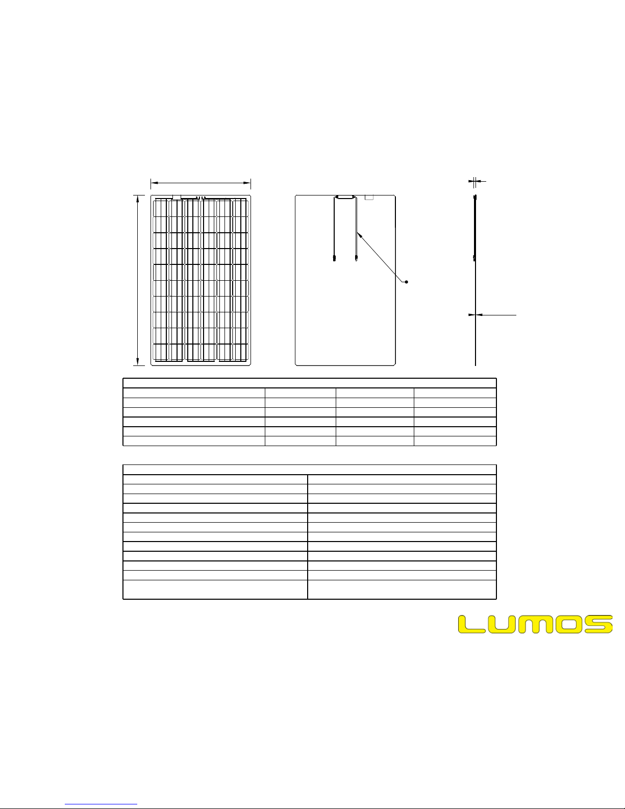
39.37"
66.93"
22.64"
Cable Length
0.95"
0.29"
Laminate Thickness
GSX Electrical Specifications
Model:
GSX260GSX265GSX270
Rated Power @STC (W)260265270
Peak Power Voltage, Vmp (V)31.3831.6331.88
Maximum Power Current, Imp (A)8.298.388.47
Open Circuit Voltage, Voc (V)39.0339.3539.66
Short Circuit Current, Isc (A)8.788.878.97
GSX Mechanical Specifications
Solar CellMonocrystalline 6” x 6”
Number of Cells60 (6 x 10)
Module Dimensions1700mm x 1000mm (66.93” x 39.37”)
Module Area1.7m² (18.30ft²)
Module Weight66.8lb (30.30kg)
Module Weight/Area3.65 psf (17.82 kg/m²)
Racking Weight/Area2.27 psf (11.08 kg/m²)
System Weight/Area5.92 psf (28.9 kg/m²)
Front Glass3.2mm Low-Iron PV Glass
Back Glass3.2mm Low-Iron PV Glass
Light Transmittance3.8%
Daylight Opening (D.L.O.)37.62” x 62.8”
(36.5” x 62.8” for modules at ends of columns)
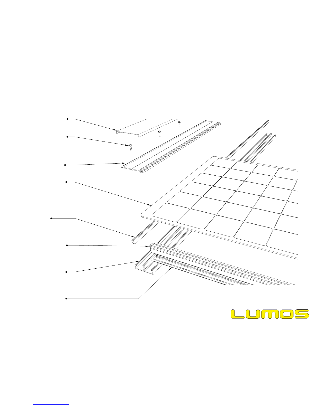
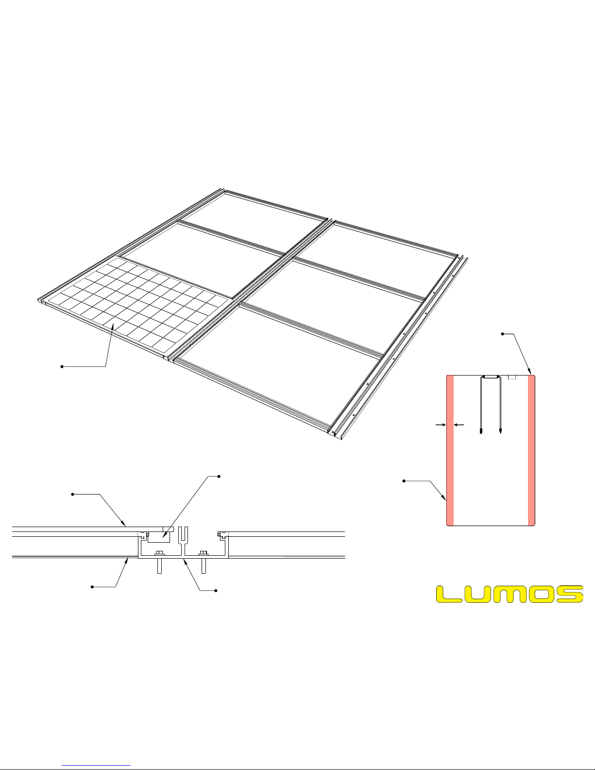
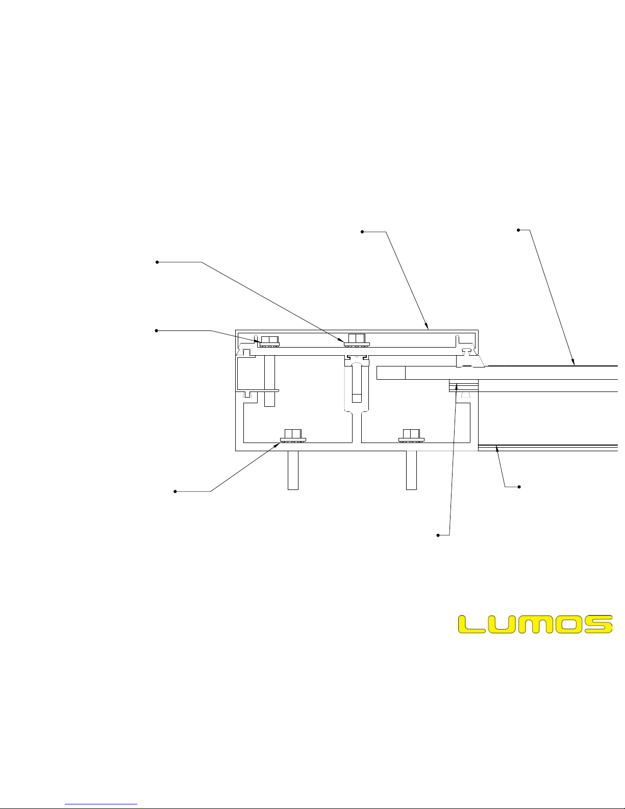
Mullion Top Cap
Pressure Plate Screws
Pressure Plate
GSX Module
Mullion Edge Filler
(Present only at
array edges)
Mullion
Transom
Page 5
Date Modified: Feb 10, 2016
File Name: 20160210_Rev004_GSX Installation Manual
Transom Bottom Cap
Mechanical Installation
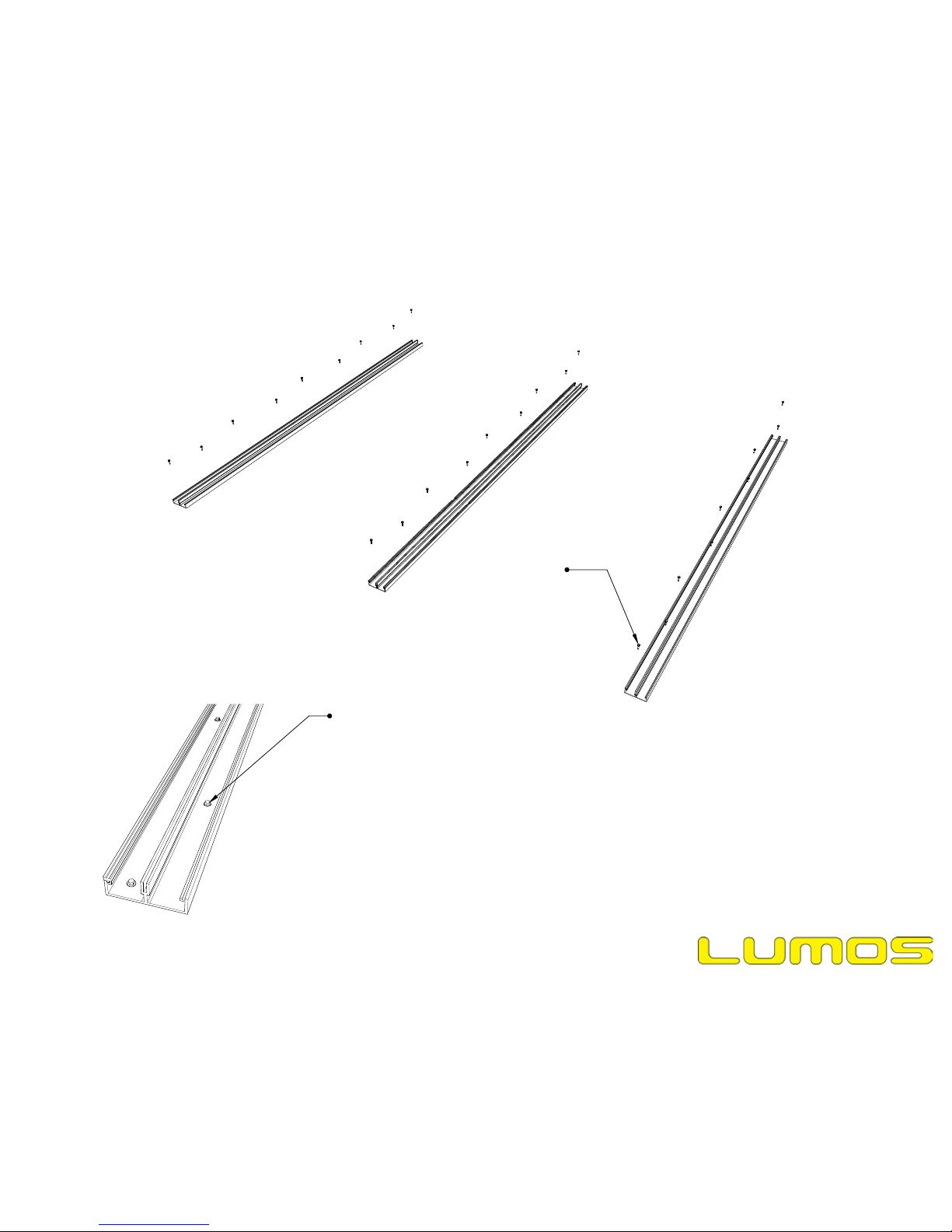
Mullion Screw
TBD per project
requirements
Mullion screws pierce
base of mullion. Pre-drilling
may or may not be required,
depending on fastener spec.
Page 6
Date Modified: Feb 10, 2016
File Name: 20160210_Rev004_GSX Installation Manual
NOTES:
1.Use only 300 series stainless steel fasteners. If using self drilling
screws, use bi-metal fasteners.
2.Lumos recommends installing galvanic isolation material between
dissimilar metals to prevent corrosion issues. This is typically an
issue where the mullions/transoms rest on a steel substructure.
Applying electrical tape or thin rubber to these areas is sufficient.
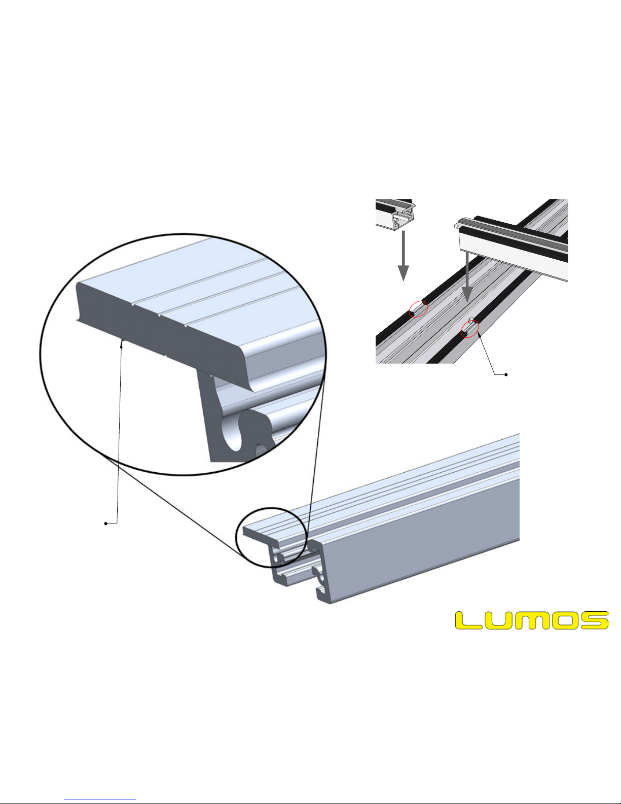
Mechanical Installation
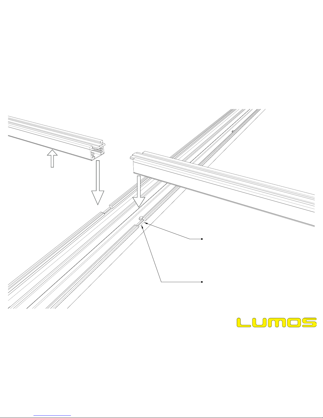
Notch rubber on mullions for
transoms. Transoms lay into
the notch. Fasteners attaching
transoms to mullions may or may
not be required, depending on
site specific conditions.
Page 7
Date Modified: Feb 10, 2016
File Name: 20160210_Rev004_GSX Installation Manual
Mechanical Installation
Snap in the Transom Bottom
Cap before placing the transom
in the Mullion Base.
Remove paint from this
area to ensure electrical
bond with transom.
Page 8
Date Modified: Feb 10, 2016
File Name: 20160210_Rev004_GSX Installation Manual
NOTES:
1.Tolerance on Mullion placement is +/- 1/8".
2.VISUALLY INSPECT each interior transom to ensure it is centered, +/- 1/16", under the gap
between modules (the modules must be dry fit in order to verify this).
3.VISUALLY INSPECT each edge transom to ensure it is flush with the edge of the module.
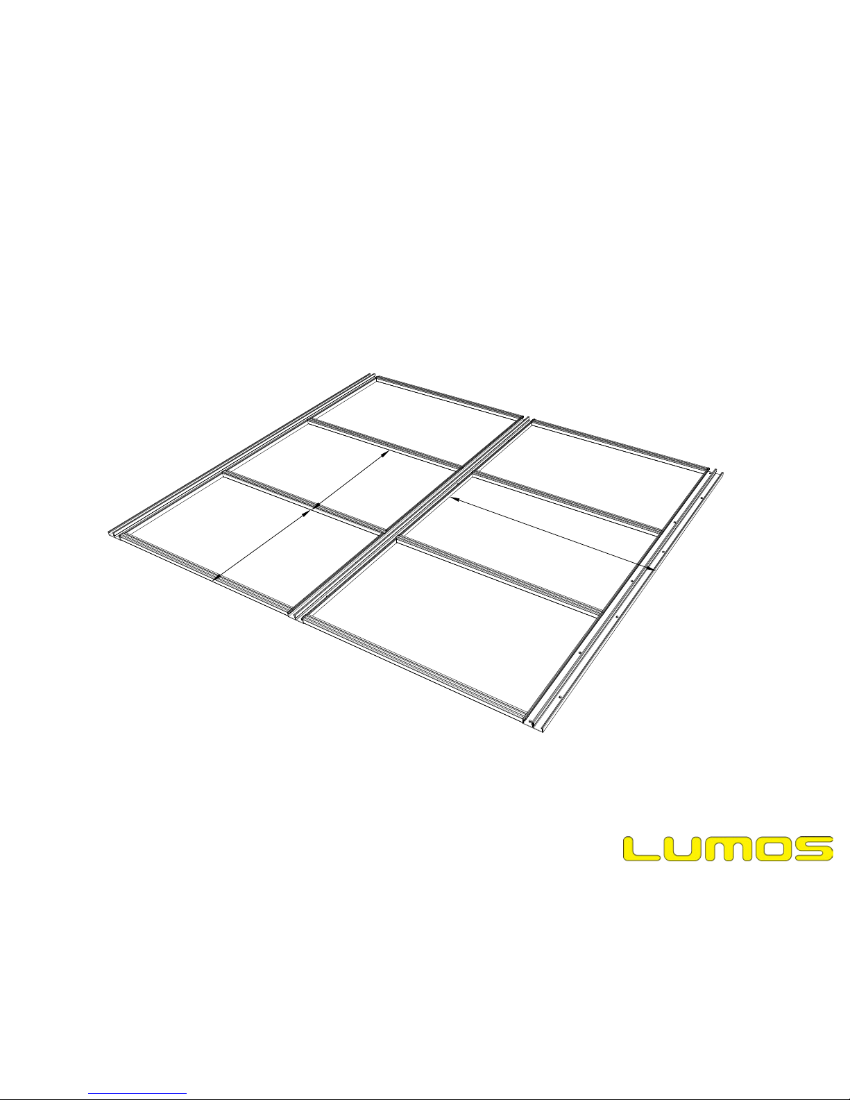
Mechanical Installation
38-1/2"
O.C. @ Edge
39-5/8"
O.C. @ Interior
67-7/8"
O.C. Everywhere
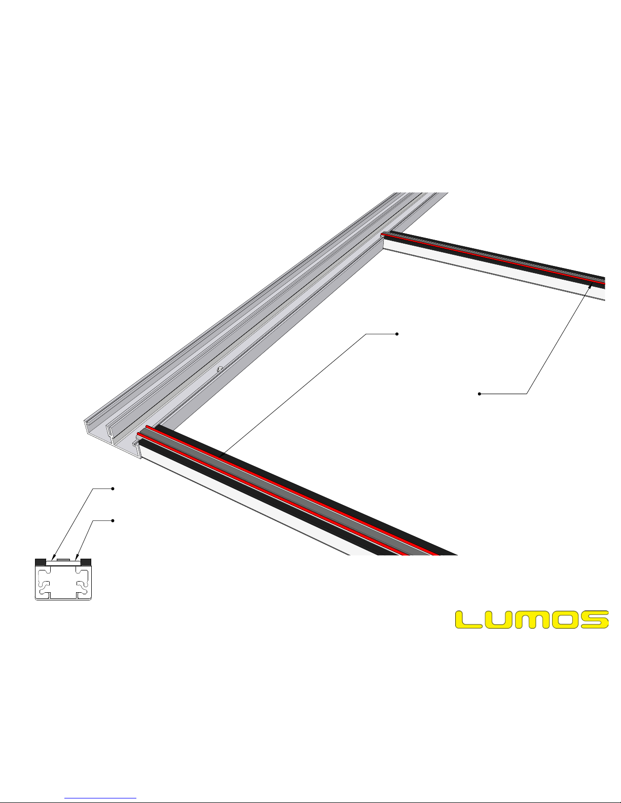
Apply caulk for first module
Apply Caulk for first module
Caulk is shown in red for
visibility. Actual color will not be
red.
Page 9
Date Modified: Feb 10, 2016
File Name: 20160210_Rev004_GSX Installation Manual
Notes:
1)Intall home run wires and/or jumpers
before installing modules. Make all
intermodule connections as modules are
placed. Once modules are installed, wire
ways will be inaccessible.
2)Clean all surfaces to be caulked as
instructed below.
Mechanical Installation
Clean this surface
prior to applying
caulk.
Clean this surface
prior to applying
caulk.
Use a cloth with isopropyl alcohol (IPA) to
clean, then wipe with a second, dry cloth.
IPA should be 70% minimum.
Cleaning:
Place first module
on racking
Junction box goes
inside mullion. Wiring
runs inside mullion.
Mullion
Transom
GSX Module
Page 10
Date Modified: Feb 10, 2016
File Name: 20160210_Rev004_GSX Installation Manual
Mechanical Installation
Clean this area
before bonding
module to transom
Clean this area
before bonding
module to transom
2" wide cleaning
area
Use a cloth with isopropyl alcohol (IPA) to
clean, then wipe with a second, dry cloth.
IPA should be 70% minimum.
Page 11
Date Modified: Feb 10, 2016
File Name: 20160210_Rev004_GSX Installation Manual
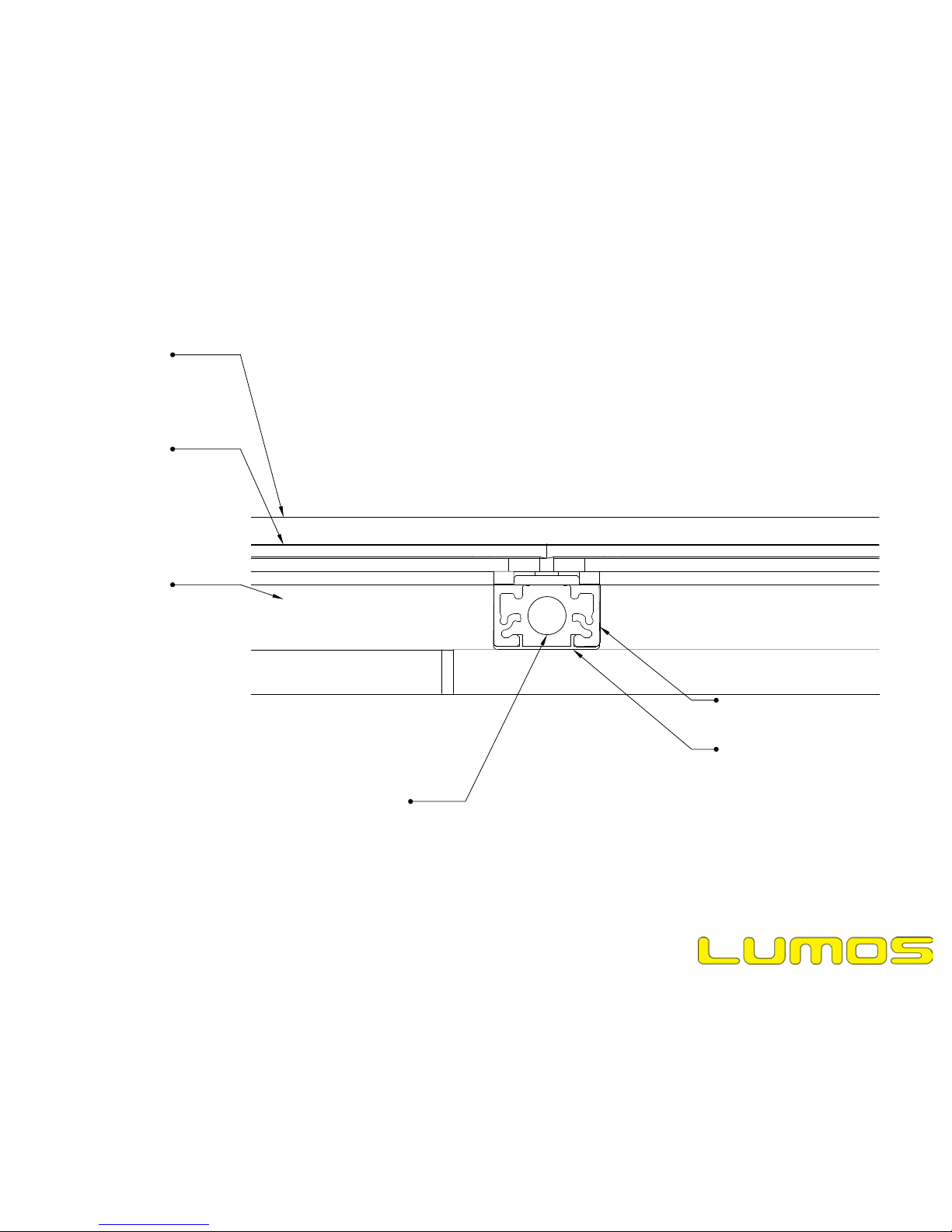
Mullion top cap
GSX Module
Mullion
Transom
Transom Bottom Cap
(snapped in during
installation)
If necessary, PV wires
can be run inside transoms
as well as mullions. This will
necessitate drilling a hole in
the mullion wall upon installation.
The circle in this view represents
an MC4 connector.
Mechanical Installation

Mullion Edge Filler
(present only at
edges of array)
Pressure Plate Screw
Pressure Plate
Page 12
Date Modified: Feb 10, 2016
File Name: 20160210_Rev004_GSX Installation Manual
Mechanical Installation
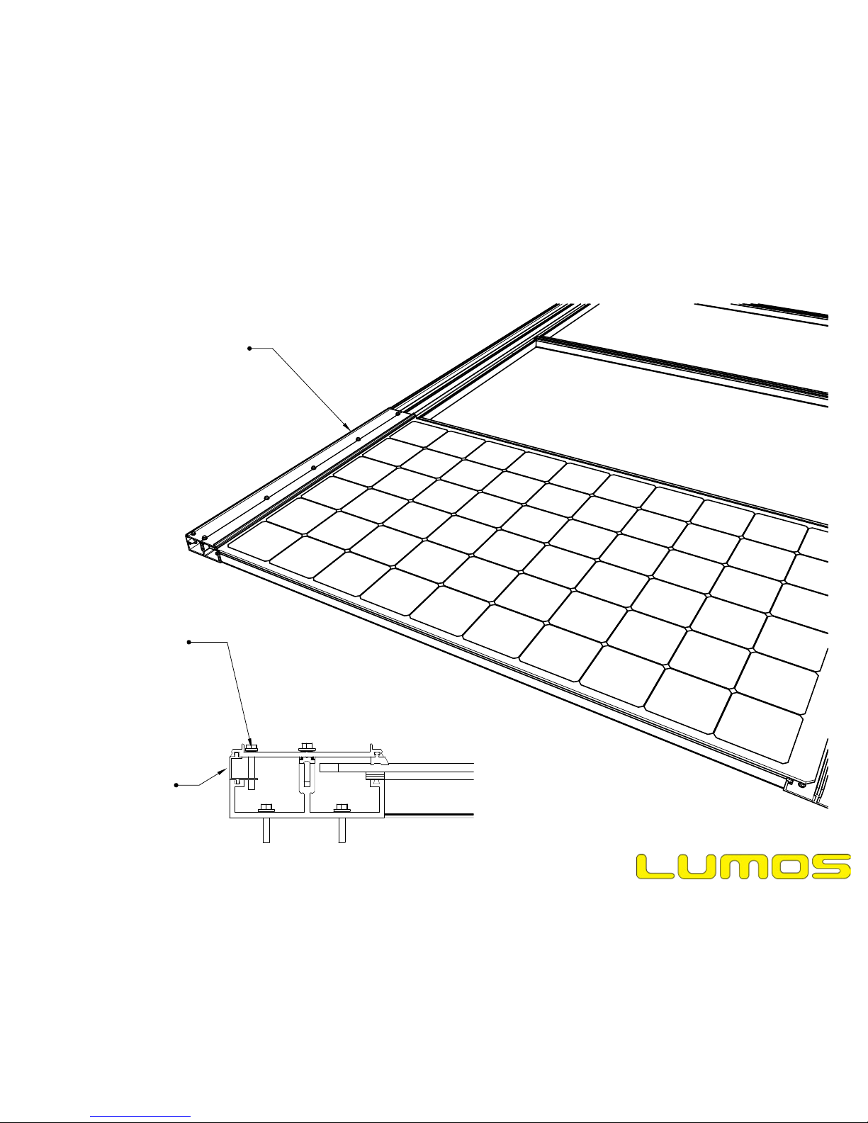
Edge filler
First pressure plate installed.
Module is also glued to transoms.
Page 13
Date Modified: Feb 10, 2016
File Name: 20160210_Rev004_GSX Installation Manual
Mechanical Installation
TORQUE SPEC:
Torque pressure plate screws to 25 in-lb.
Install one grounding
screw per section of
mullion edge filler. Drill
1/4" through hole in
pressure plate and use
drill tip on screw to
penetrate mullion edge
filler. (see electrical
installation section of this
manual.)

Apply caulk for 2nd module
Apply caulk for 2nd module
1st module (already installed)
Caulk is shown in red for
visibility. Actual color will not be
red.
Page 14
Date Modified: Feb 10, 2016
File Name: 20160210_Rev004_GSX Installation Manual
Mechanical Installation

Place 2nd module on racking
Jbox of 2nd module can be in
either mullion. Grouping jboxes
into the same mullion can
simplifiy wire management.
Wires run inside mullion.
Page 15
Date Modified: Feb 10, 2016
File Name: 20160210_Rev004_GSX Installation Manual
Mechanical Installation
Use a cloth with isopropyl alcohol (IPA) to
clean, then wipe with a second, dry cloth.
IPA should be 70% minimum.

2nd pressure plate installed
3rd pressure plate installed
Page 16
Date Modified: Feb 10, 2016
File Name: 20160210_Rev004_GSX Installation Manual
Mechanical Installation
Apply caulk for 3rd module
Apply caulk for 3rd module
Caulk is shown in red for
visibility. Actual color will not be
red.
Page 17
Date Modified: Feb 10, 2016
File Name: 20160210_Rev004_GSX Installation Manual
Mechanical Installation
Use a cloth with isopropyl alcohol (IPA) to
clean, then wipe with a second, dry cloth.
IPA should be 70% minimum.
Place 3rd module on racking
Page 18
Date Modified: Feb 10, 2016
File Name: 20160210_Rev004_GSX Installation Manual
Mechanical Installation

Install 4th pressure plate
Page 19
Date Modified: Feb 10, 2016
File Name: 20160210_Rev004_GSX Installation Manual
Mechanical Installation
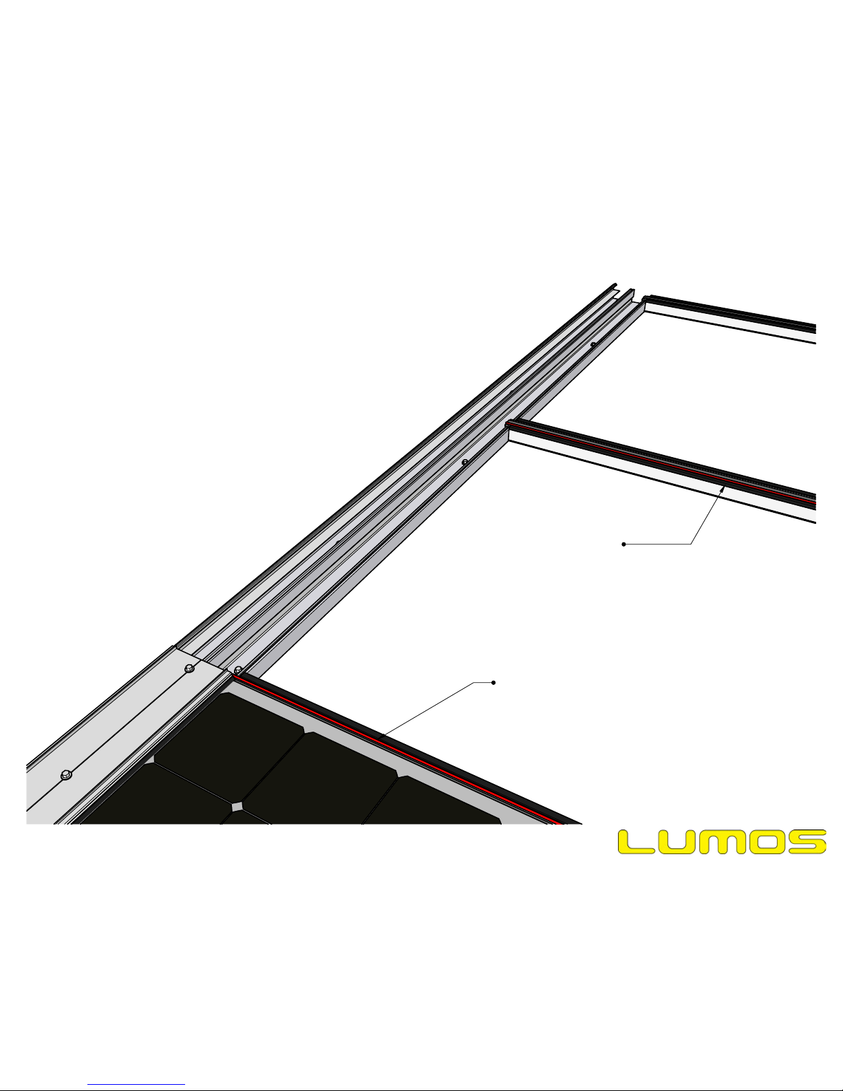
Caulk is shown in green for
visibility. Actual color will not be
green.
Install weatherseal (i.e., caulk
the joint. Tape off and tool back
to ensure a clean finish.)
Page 20
Date Modified: Feb 10, 2016
File Name: 20160210_Rev004_GSX Installation Manual
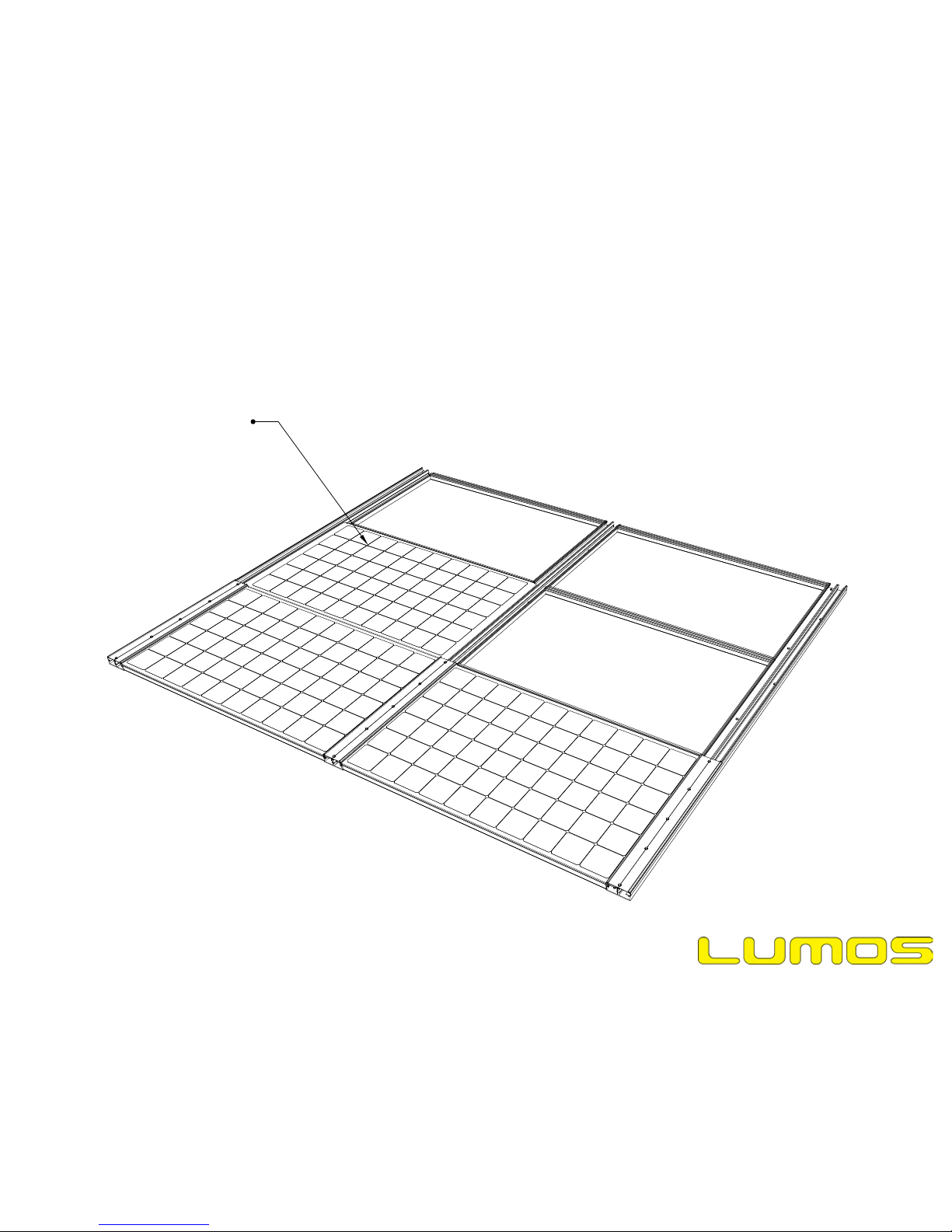
Mechanical Installation
Install the next module.
This includes caulking the
transoms, and installing
the pressure plate(s).
Pressure plate
Pressure plate
Page 21
Date Modified: Feb 10, 2016
File Name: 20160210_Rev004_GSX Installation Manual
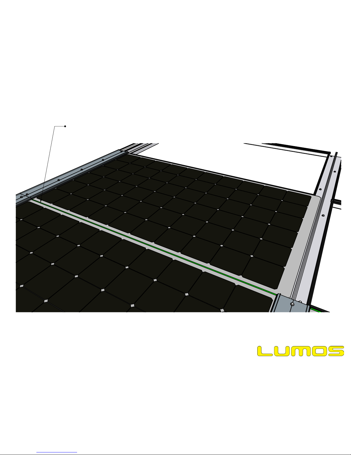
Mechanical Installation
Install weatherseal
Caulk is shown in green for
visibility. Actual color will not be
green.
Page 22
Date Modified: Feb 10, 2016
File Name: 20160210_Rev004_GSX Installation Manual
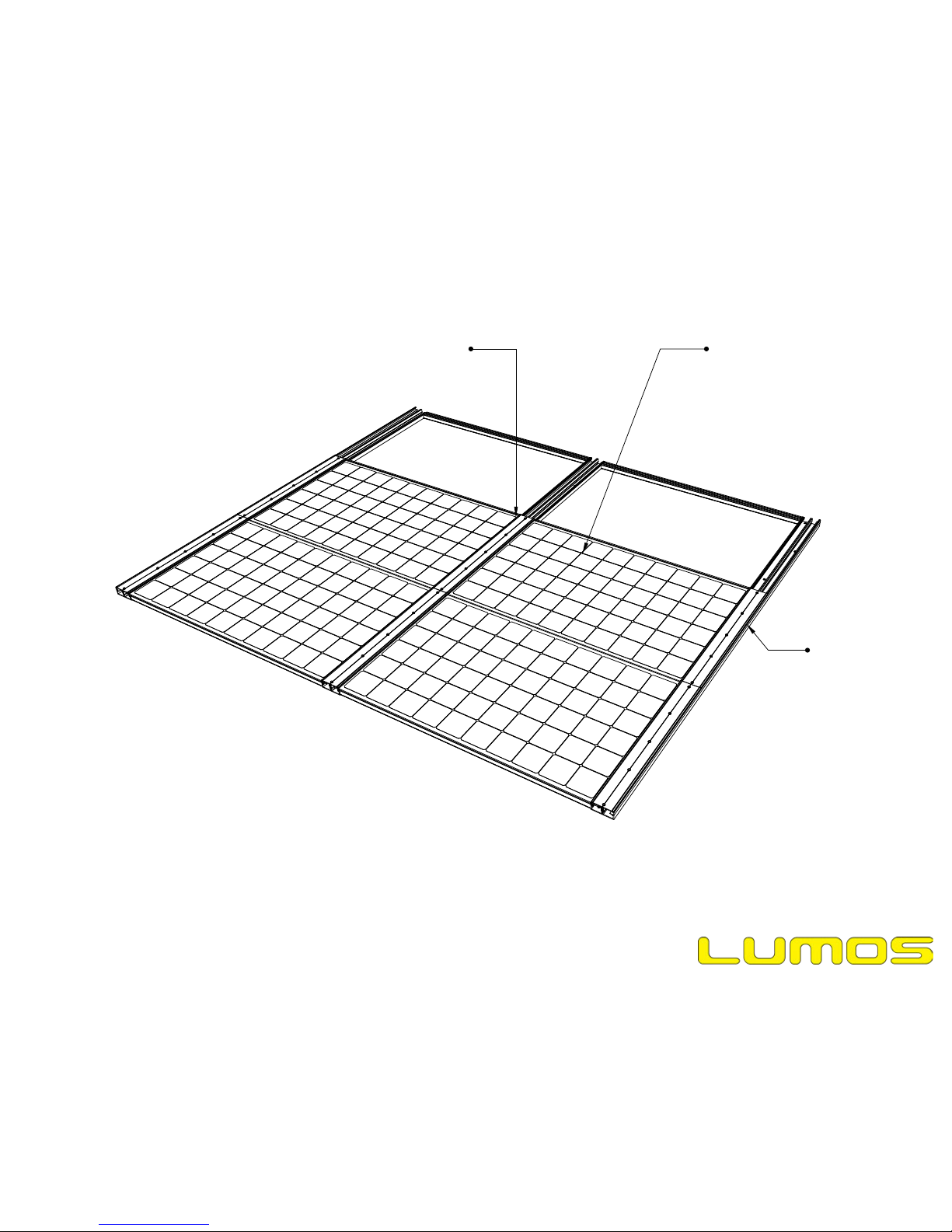
Mechanical Installation

Follow the same pattern to install the rest of the modules. Be sure to apply caulk to the transoms
and weatherseals. All wiring must be completed as the modules are installed, as the wire ways will be
inaccessible once all modules are in place.
Page 23
Date Modified: Feb 10, 2016
File Name: 20160210_Rev004_GSX Installation Manual
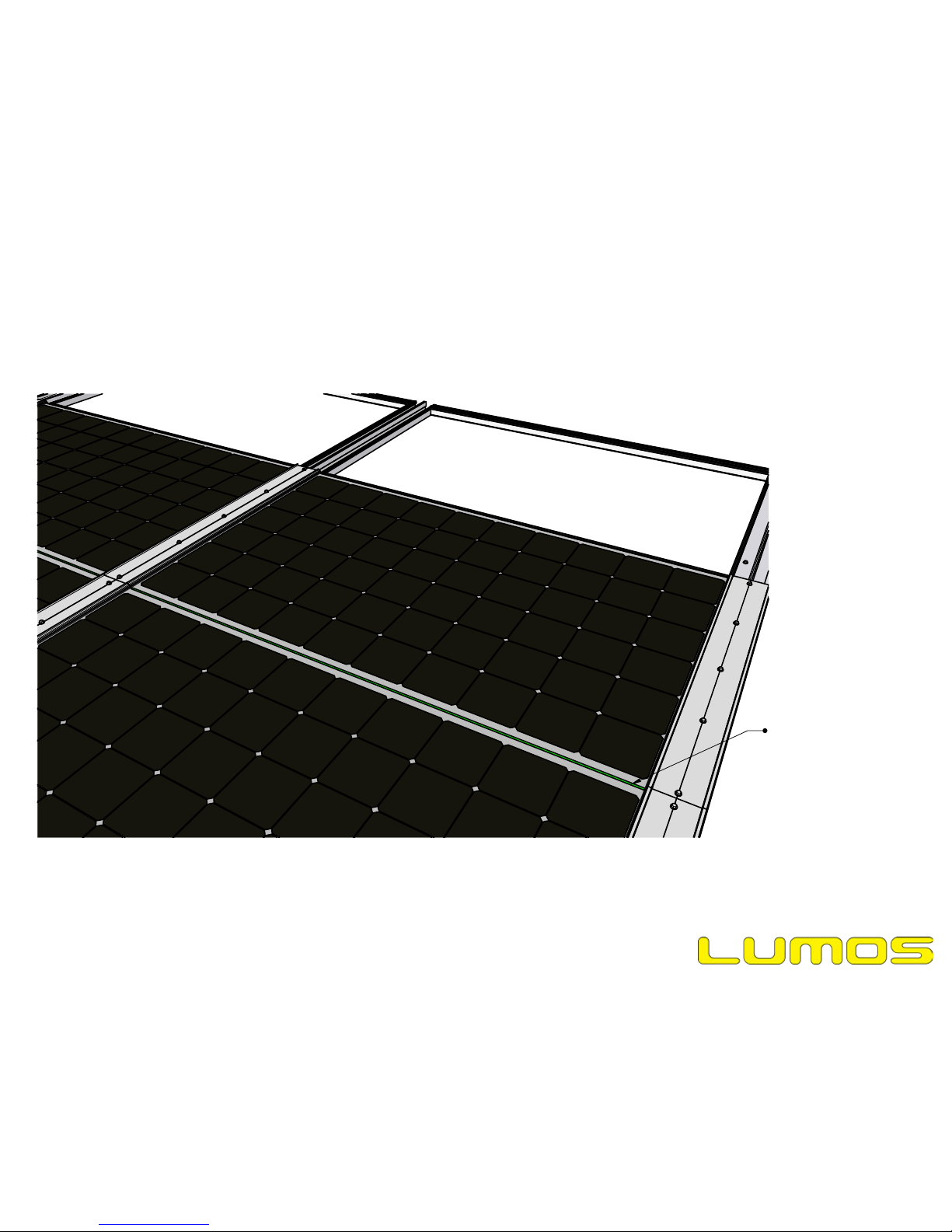
Mechanical Installation

Install mullion top caps
by snapping them onto
pressure plates. A rubber
mallet works well.
Install mullion end caps
with included screws.
Page 24
Date Modified: Feb 10, 2016
File Name: 20160210_Rev004_GSX Installation Manual
Mechanical Installation
Page 25
Date Modified: Feb 10, 2016
File Name: 20160210_Rev004_GSX Installation Manual
Electrical Installation
Grounding/Electrical Bonding Information
(continued on next page)
Top Cap is bonded to pressure
plate via direct metal to metal
contact inside the snap fit
Mullions can be gounded to
conductive substructure by fastener
with star washer.
Transom has grounding teeth
which ensure electrical bond
with mullion (remove any paint
from mullion with coarse
sandpaper, 40 grit
recommended)
Module is frameless, so
no grounding is required
1/4-14 SS self tapping screw
with SS star washer bonds
pressure plate to mullion
12-24 SS self drilling screw
with SS star washer bonds
mullion edge filler to pressure
plate. One screw per mullion
edge filler length. REQUIRES
FIELD DRILLING A 1/4"
THROUGH HOLE IN PRESSURE
PLATE.
Transom bottom
cap is bonded to
transom via direct
metal to metal
contact inside the
snap fit
Note:
All hardware must be 300 series stainless steel.
Page 26
Date Modified: Feb 10, 2016
File Name: 20160210_Rev004_GSX Installation Manual
Grounding Teeth on
transom ensure
electrical bond with
mullion.
Electrical Installation
Grounding/Electrical Bonding Information
(continued on next page)
Remove any paint
from mullion with
coarse sandpaper,
40 grit
recommended)
Page 27
Date Modified: Feb 10, 2016
File Name: 20160210_Rev004_GSX Installation Manual
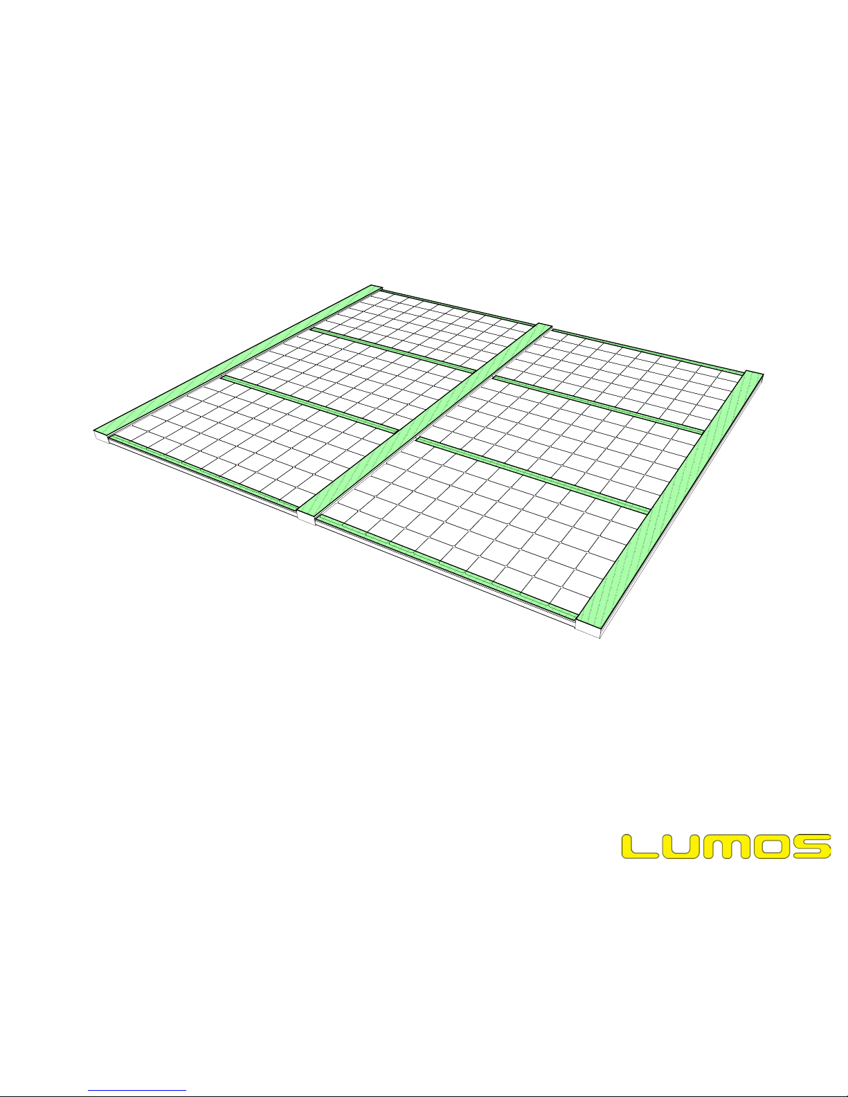
Walking on the Array
Lumos permits stepping and walking on our GSX modules, but ONLY OVER THE TRANSOMS AND MULLIONS. Stepping
anywhere other than these locations, which are highlighted in green with hatch marks in the above image, could cause damage
to the solar cells and lower the power output of the module.
Page 28
Date Modified: Feb 10, 2016
File Name: 20160210_Rev004_GSX Installation Manual
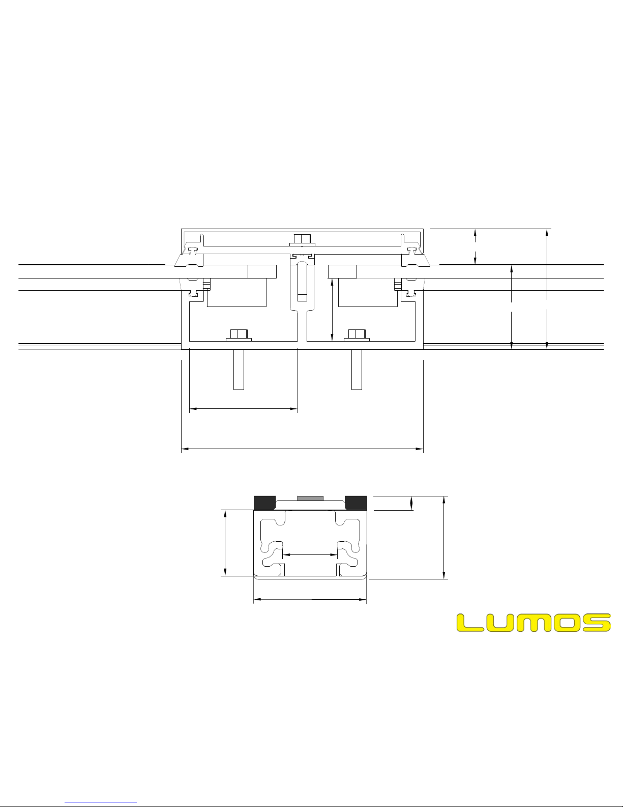
5"
1 5/16"
1 3/4"
Useful Dimensions:
2"
1/4"
1 3/16"1"1 1/2"
2 1/4"
2 1/2"
3/4"

Page 29
Date Modified: Feb 10, 2016
File Name: 20160210_Rev004_GSX Installation Manual
Useful Dimensions:

Page 30
Date Modified: Feb 10, 2016
File Name: 20160210_Rev004_GSX Installation Manual
Returns
Returns are only accepted with an approved RMA (Return Material Authorization) form. Returns must be packed appropriately, as the product was received, in
the original packaging. Improperly packed returns will not be credited. If original packaging has been discarded or lost, contact Lumos for instructions.
For questions regarding RMA forms or to submit an RMA form, please contact Lumos directly.
Contact Lumos
For more information on the Lumos GSX Module System, GSX installation processes, maintenance, warranties, purchasing inquiries, finding an authorized
dealer, or for more information on any other Lumos products and services, please contact:
Lumos Solar
929 Pearl St., Ste. 250
Boulder, CO 80302
Tel: (877) 301 - 3582
Fax: (303) 442 - 1829
info@lumossolar.com
 Loading...