


TM
LCX-15MT
INSTALLATION AND
OPERATION INSTRUCTIONS
WWW.LOWRANCE.COM
75

Copyright © 2001 Lowrance Electronics, Inc.
All rights reserved.
LCX-15MT is a trademark of Lowrance Electronics, Inc.
Lowrance® is a registered trademark of Lowrance Electronics, Inc.
WARNING!
USE THIS UNIT ONLY AS AN AID TO NAVIGATION. A CAREFUL NAVIGATOR NEVER RELIES ON ONLY ONE METHOD TO OBTAIN POSITION INFORMATION.
Never use this product while operating a vehicle.
CAUTION
When showing navigation data to a position (waypoint), this unit will show the shortest, most direct path to the waypoint. It provides navigation data to the waypoint regardless of obstructions.Therefore, the prudent navigator will not only take advantage of all available navigation tools when travelling to a waypoint, but will also visually check to make certain a clear, safe path to the waypoint is always available.
The operating and storage temperature for your unit is from -4 degrees to +167 degrees Fahrenheit (-20 to +75 degrees Celsius). Extended storage temperatures higher or lower than specified will cause the liquid crystal display to fail. Neither this type of failure nor its consequences are covered by the warranty. For more information, consult the factory customer service department.
All features and specifications subject to change without notice.
Lowrance Electronics may find it necessary to change or end our policies, regulations, and special offers at any time.We reserve the right to do so without notice.
All screens in this manual are simulated.
NOTICE!
Free software upgrades will be available on our website at http:// www.lowrance.com/lcx as they are released. Please check our website periodically for these and other information as they become available.
Thank you for choosing Lowrance!

This device complies with Part 15 of the FCC Rules. Operation is subject to the following two conditions: (1) this device may not cause harmful interference, and (2) this device must accept any interference received, including interference that may cause undesired operation.
Note:
This equipment has been tested and found to comply with the limits for a Class B digital device, pursuant to Part 15 of the FCC Rules. These limits are designed to provide reasonable protection against harmful interference in a residential installation.This equipment generates, uses and can radiate radio frequency energy and, if not installed and used in accordance with the instructions, may cause harmful interference to radio communications. However, there is no guarantee that interference will not occur in a particular installation. If this equipment does cause harmful interference to radio or television reception, which can be determined by turning the equipment off and on, the user is encouraged to try to correct the interference by one or more of the following measures:
•Reorient or relocate the receiving antenna.
•Increase the separation between the equipment and receiver.
•Connect the equipment into an outlet on a circuit different from that to which the receiver is connected.
•Consult the factory customer service department for help.
SPECIFICATIONS |
|
Dimensions (on bracket) ........................ |
9.6” W x 7.3” H x 3.7” D |
Input Voltage .......................................... |
10 - 15 vDC, 12-volt Nominal |
Transmitter Frequency ........................... |
200 kHz and 50 kHz |
Maximum Output Power |
200 kHz - 500 watts (RMS) |
|
50 kHz - 1,000 watts (RMS) |
Display ................................................... |
6.54” diagonal |
|
Monochrome Transflective |
|
350 pixel H x 480 pixel W |
Operating and Storage Temperature ...... |
-4 to +167 degrees Fahrenheit |
|
-20 to +75 degrees Celsius |
Waypiont ................................................ |
750 |
Routes .................................................... |
100 |
Icons ...................................................... |
1000 |
NMEA 2.0 GPS Sentences .................... |
GLL, GGA, APB, RMB, RMC, |
|
GSA, GSV |
NMEA 2.0 Sonar Sentences .................. |
DBT, DPT, MTW, VLW, VHW |
Table of Contents
INTRODUCTION ................................................ |
1 |
ACCESSORIES ................................................. |
1 |
TRANSDUCERS ................................................ |
1 |
INSTALLATION ................................................... |
2 |
Mounting ......................................................... |
2 |
Power Connections ......................................... |
3 |
NMEA/DGPS Wiring ....................................... |
4 |
Accessory Connections .................................. |
5 |
Speed/Temperature Sensor ...................... |
5 |
MMC ................................................................... |
7 |
KEYBOARD ........................................................ |
8 |
SONAR OPERATION ......................................... |
9 |
Pages .............................................................. |
9 |
Full Sonar Chart ........................................ |
9 |
Split Zoom Chart ....................................... |
9 |
Split Frequency Sorna Chart .................... |
9 |
Digital/Chart ............................................ |
10 |
Customizing the Digital/Chart Screen .... |
11 |
Menus ........................................................... |
11 |
Sonar Options ............................................... |
12 |
Sensitivity ................................................ |
12 |
Automatic Sensitivity ............................... |
12 |
Grayline® .................................................................................. |
13 |
Range - Automatic .................................. |
13 |
Manual ............................................... |
14 |
Range - Upper/Lower Limits ................... |
14 |
Zoom ....................................................... |
15 |
Chart Stop ............................................... |
15 |
Chart Speed ............................................ |
15 |
Depth Cursor ........................................... |
15 |
Chart Data ............................................... |
16 |
Sonar Features ....................................... |
16 |
Transducer Frequency ....................... |
17 |
Surface Clarity ................................... |
17 |
Noise Rejection ................................. |
17 |
Fish Symbols/Fish Depths ................ |
18 |
Log Sonar Chart Data ............................. |
19 |
Display Settings ...................................... |
19 |
Contrast/Backlight/Display Mode ...... |
19 |
Audio ....................................................... |
20 |
Alarms ..................................................... |
20 |
Depth Alarms ..................................... |
21 |
Zone Alarm ........................................ |
21 |
Fish Alarm ......................................... |
22 |
Sonar Setup ............................................ |
22 |
Transducer Type ................................ |
22 |
Keel Offset ......................................... |
23 |
Calibrate Speed ................................. |
23 |
Reset Water Distance ........................ |
23 |
Sonar Simulator ................................. |
24 |
System Setup .......................................... |
24 |
Units of Measure ............................... |
24 |
Set Local Time ................................... |
25 |
Communication Ports ........................ |
25 |
Configure DGPS ................................ |
26 |
Configure NMEA ............................... |
26 |
Reset Options .................................... |
26 |
Popup Help ........................................ |
27 |
Hide GPS Features ........................... |
27 |
Software Information ......................... |
27 |
Sun/Moon Calculator .............................. |
27 |
GPS OPERATION ............................................ |
28 |
Introduction to GPS ...................................... |
28 |
Finding Your Position ..................................... |
30 |
Auto Search ............................................ |
30 |
Manual Initialization ................................. |
30 |
Position Acquisition ................................. |
31 |
Require DGPS ........................................ |
32 |
PAGES .................................................... |
32 |
Status Screen .................................... |
32 |
Customizing the Status Screen ......... |
33 |
Navigation Screen ................................... |
33 |
Customizing the Navigation Screen .. |
34 |
Map ....................................................... |
34 |
Full Map ............................................. |
35 |
Digital Data ........................................ |
35 |
Two Position Formats ........................ |
36 |
Two Maps .......................................... |
36 |
Map with Sonar ................................. |
36 |
Cursor ................................................ |
36 |
Cursor Distance ............................. |
37 |
Map Orientation ....................................... |
37 |
Auto Zoom ............................................... |
39 |
Range Rings/Grid Lines .......................... |
39 |
Map Data ................................................. |
39 |
Map Categories Drawn ........................... |
40 |
Icons ....................................................... |
40 |
Plot Trail ................................................... |
41 |
Edit Trail ............................................. |
42 |
Navigate a Trail .................................. |
42 |
Trail Options ....................................... |
44 |
New Trail ........................................ |
44 |
Delete All Trails .............................. |
44 |
Waypoints ................................................ |
45 |
Saving Present Position .................... |
45 |
Saving Cursor Position ...................... |
45 |
Saving a New Position ....................... |
46 |
Edit Waypoint ................................. |
46 |
Average Position ............................ |
47 |
Waypoint Information ......................... |
47 |
Waypoint Navigation .......................... |
48 |
Navigate to Cursor ......................... |
48 |
Navigate to Waypoint using Map ... |
48 |
Man Overboard ....................................... |
49 |
Cancel Navigation ................................... |
50 |
Routes ..................................................... |
50 |
Create a Route .................................. |
51 |
Follow a Route ................................... |
53 |
GPS Simulator ........................................ |
53 |
GPS Setup .............................................. |
54 |
Coordinate System ............................ |
54 |
Map Fix .............................................. |
55 |
Datum ................................................ |
56 |
Position Pinning ................................. |
57 |
GPS Alarms ............................................ |
58 |
Sonar Troubleshooting ...................................... |
59 |
Warranty Information ........................................ |
62 |
Datum List ....................................................... |
63 |
Database License Agreement .......................... |
66 |
Database Limited Warranty .............................. |
67 |
Saving and Replaying a Sonar Record ............ |
68 |
Transferring GPS Data to/from a MMC ............ |
69 |
INTRODUCTION
Thank you for purchasing a Lowrance product. No other combination sonar/GPS receiver has the features of the LCX-15MT. Countless hours went into the design of this product. We hope that you enjoy using it as much as we have.
The LCX-15MT is sold with many different accessories. Some are packed with a GPS receiver, MMC, and mapping CD-ROM. Others are sold only with a transducer. Many may come with different combinations of accessories.
Please note that you may need to purchase accessories in order to use all of the features of this product that are described in this manual. A list of the accessories and transducers is shown below.
ACCESSORIES |
Model |
Part # |
Gimbal Knobs ........................................ |
GK-9 ............................ |
101-80 |
Gimbal Bracket ........................................ |
GB-12 ......................... |
101-78 |
Power Cable ............................................ |
PC-21X ......................... |
99-56 |
Protective Cover ...................................... |
CVR-1 ......................... |
101-82 |
Sun Shade .............................................. |
SS-1 ............................ |
101-83 |
MMC Drawer ........................................... |
MMCD-1 ..................... |
101-84 |
MMC Interface ......................................... |
MMCI .......................... |
101-85 |
Cigarette Adapter Cable .......................... |
CA-4 ............................. |
99-59 |
Power Connector Repair Kit .................... |
TC-4X ......................... |
101-86 |
MMC Card 8MB ...................................... |
MMC-8 ........................ |
101-87 |
MMC Card 16MB .................................... |
MMC-16 ...................... |
101-88 |
Transducer Extension Cable (12') ........... |
XT-12 ............................ |
99-57 |
Transducer Extension Cable (20') ........... |
XT-20X .......................... |
99-58 |
Speed/Temp Y-adapter Cable .................. |
MY-4X ........................... |
99-53 |
Speed/Temp Sensor w/ MY-4X ............... |
ST-TX ............................ |
99-54 |
Temp Sensor 1 w/ MY-4X ........................ |
TS-1X ........................... |
99-50 |
Temp Sensor 2 ........................................ |
TS-2X ........................... |
99-51 |
Temp Sensor 3 ........................................ |
TS-3X ........................... |
99-52 |
Transducers |
|
|
|
Model |
Part # |
200 kHz “Skimmer” .................... |
HS-WSDX .................... |
106-22 |
High Speed Transom |
|
|
mount w/temp sensor |
|
|
200 kHz “Pod” Transducer .......... |
PD-WDXT ..................... |
106-26 |
w/temp sensor for trolling |
|
|
motor application |
|
|
1
Transducers (cont.) |
|
|
|
Model |
Part # |
200 kHz “Pod” Transducer .......... |
PD-WDX ....................... |
106-27 |
w/o temp for shoot-thru hull |
|
|
50/200 kHz Dual Freq. ............... |
HS-50/200-DX .............. |
106-23 |
“Skimmer” High Speed |
|
|
Transom mount with |
|
|
temp sensor |
|
|
50/200 kHz Dual Freq. ............... |
THST-50/200-DX .......... |
106-29 |
Bronze thru-hull mount |
|
|
w/temp and speed sensor |
|
|
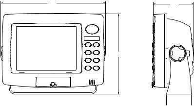
INSTALLATION Bracket
Install the unit in any convenient location, provided there is clearance behind it when it is tilted for the best viewing angle. Holes in the bracket base allow wood screw or through-bolt mounting. Make certain there is enough room behind the unit to attach the power and other cables.
9.6” |
3.7” |
|
7.3” |
 2.3”
2.3” 
Once the best location is determined, use the bracket as a template and mark the mounting holes and the hole for the cables. Drill a 1.0" hole for the cables. Screw the bracket to the mounting surface.
IMPORTANT!
In order to pass all connectors through the 1" hole in the bracket and dash, first pass the transducer connector up through the hole, then any accessory cables. Next, pass the power cable down through the hole. Fill the hole with a marine sealant. You can now wire the power cable.
2
Power Connections
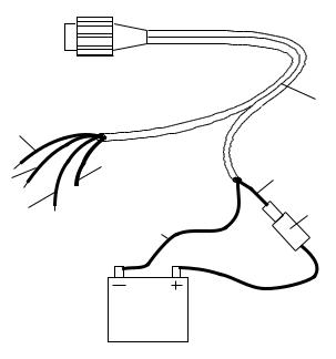
This unit operates from a 12-volt battery system. For the best results, connect the power cable to the in-line fuse holder and attach it directly to the battery. The power cable can be attached to an accessory or power buss, however there could be problems with electrical interference using this method. Therefore, it’s better from a noise standpoint to attach the power cable and fuse holder directly to a battery. If the cable is not long enough, splice 16-gauge wire onto it.
The power connector has two cables attached to it. One cable has the power and ground wires, the other is for the NMEA/DGPS interface. See below for NMEA/DGPS wiring instructions.The power cable has two wires - red and black. The black wire connects to the battery’s negative terminal.The red wire is the positive wire. Connect it to the fuse holder supplied with the unit. Connect the other end of the fuse holder to the positive side of the battery. Make certain to attach the fuse holder directly to the battery. This will protect the both cable and the unit in case there is a short circuit. Use a 6-amp fuse.
TO POWER
CONNECTOR
|
|
POWER |
|
|
|
CABLE |
|
YELLOW |
|
|
|
|
SHIELD |
RED |
|
ORANGE |
WIRE |
||
|
|||
|
|
||
BLUE |
|
6-AMP |
|
BLACK |
FUSE |
||
|
|||
|
WIRE |
|
12-VOLT BATTERY
IMPORTANT!
Do not use this product without a 6-amp fuse connected to the power cable! Failure to use a fuse will void your warranty.
3
To prevent electrical interference, route the power, transducer, and GPS cables away from other wiring, especially the engine’s wiring harness. VHF radio antenna cables radiate noise when transmitting, so be certain to keep the unit’s wires away from it, also.
NMEA/DGPS
NMEA is a standard communications format for marine electronic equipment. For example, an autopilot can connect to the NMEA interface on the LCX-15MT and receive positioning information.
DGPS is an acronym for Differential Global Positioning System.The most popular DGPS system relies on a grid of ground-based transmitters that send correction signals to DGPS receivers. These in turn, connect to the GPS receiver (such as the LCX-15MT with the LGC-12S GPS module). This gives more accurate positions than is otherwise possible.
NMEA/DGPS Wiring
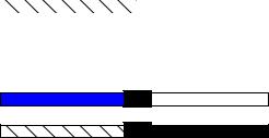
The LCX-15MT has two NMEA 0183 version 2.0 ports. Com port one can be used for either NMEA or DGPS, Com port two is for NMEA output only.
Comunications port one uses the yellow wire wire for transmit, the orange wire for receive. Comunications port two uses the blue wire for transmit. Both ports use the shield wire for signal ground.
See the diagrams below for general wiring connections. Read your other product’s owner’s manual for more wiring information.
COM-1
LCX-15MT
COM-2
LCX-15MT
YELLOW (TRANSMIT) |
RECEIVE |
|
|
|
|
ORANGE (RECEIVE) |
|
TRANSMIT |
|
|
|
SHIELD (GROUND) |
|
GROUND |
|
|
|
BLUE(TRANSMIT) |
RECEIVE |
SHIELD (GROUND) |
GROUND |
TO BEACON RECEIVER
TO OTHER
DEVICE
4
COM-1
LCX-15MT
ORANGE (RECEIVE)
SHIELD (GROUND)
NMEA TRANSMIT
GROUND
FROM GPS RECEIVER
The LCX-15MT can accept position information from any GPS receiver that transmits NMEA 0183 data. Use the wiring diagram shown above for NMEA input to the LCX-15MT.
See page 25 and 26 for NMEA and DGPS com port setup instructions.
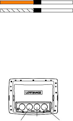
Accessory Connections
The rear of this unit has three connectors: Power/Data, GPS, and Transducer. The power cable connects to the Power/Data connector, the cable from the GPS module goes to the GPS connector, and the transducer plugs into the Transducer connector.
|
LOWRANCE |
|
PWR/DATA |
GPS MODULE |
TRANSDUCER |
Speed/Temperature Connections
This unit can use a speed sensor in addition to up to three temperature sensors.
All transom-mount “Skimmer” transducers have a temperature sensor built into them. To add another temperature sensor besides the one in the transducer requires a MY-4X “Y” adapter cable and a TS-2X temperature sensor. The transducer plugs into one end of the MY-4X, the TS-2X temperature sensor plugs into another, and the last end plugs into the SONAR port. The TS-2X temperature sensor has an extra connector for a TS-3X temperature sensor. This lets you have three temperature sensors, if desired.
Note: Do not combine the temperature sensors in any order other than shown on the next page. For example, do not use two TS-3X temperature sensors in place of one TS-2X and one TS-3X sensors. Each sensor is programmed to work only on the channel it’s designed for.
5
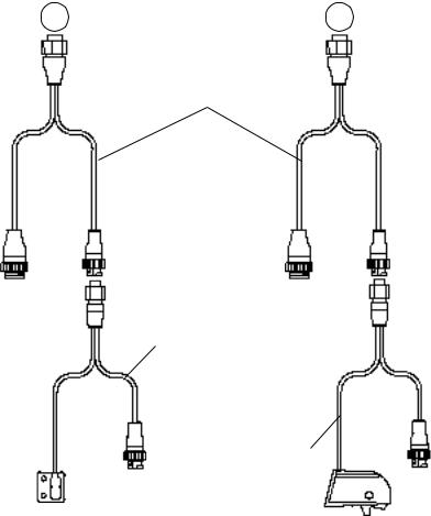
Temperature and Speed/Temperature Installation Examples
X-15MT |
X-15MT |
Sonar Connector |
Sonar Connector |
“Y” Adapter Cable (Packed with Speed/Temp Sensor)
To |
To |
Transducer |
Transducer |
|
Temperature Sensor |
|
Speed/Temp Sensor |
To |
To |
Additional |
Additional |
Temp. or |
Temp. |
Speed |
Sensors |
Sensors |
(if needed) |
(if needed) |
|
6
MMC
This unit can use up to two MMC (MultiMediaCard) cartridges.They store the maps, waypoint and route information, sonar data, and more.
To install a MMC cartridge, twist the drawer retainer counter-clockwise and pull. The drawer will come out of the unit. Place the MMC cartridge FACE DOWN. (see above) Slide the drawer back into the unit and twist the retainer clockwise. The MMC is now ready for use.
For more information on saving and recalling sonar data to the MMC, see page 68.
Map storage requires the MapCreate™ software and a MMC Interface. If your unit did not come with these, they are available for purchase separately.
You can also store plot trails, icons, waypoints, and routes on a MMC. See page 69 for more information.
7
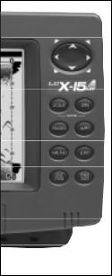
KEYBOARD
The keyboard has keys arranged in two vertical columns beneath the arrow keys. The menu key near the bottom left corner of the keyboard activates the first menu page. The other keys are used to zoom the display, change modes, and other functions.
ZOUT/ZIN - These keys “zoom” the map or the sonar screen in and out.
PAGES - This key switches the unit between different sonar or GPS modes.
WPT - Saves and recalls waypoints.
MENU - Press this key to show the menus and gain access to most functions.
EXIT - Clears menus and entries.
ENT/ICONS - Used to select entries and accept menu selections. When a menu is not showing, pressing this key activates the ICON menu.
PWR/LIGHT - Turns the unit on and off. When the unit is on, pressing this key turns the backlights on or off.
Note: Pressing the PWR/LIGHT key repeatedly changes the backlight level. There are three levels available.
8
SONAR OPERATION
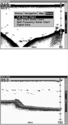
PAGES
Turn the unit on by pressing the PWR/LIGHT key. If the sonar screen is not showing, press the PAGES key. A menu similar to the one at right appears. Press the left or right arrow key to highlight the Sonar label. This gives you four selections: Full Sonar Chart, Split Zoom Sonar Chart, Split (Dual) Frequency Sonar Chart, or Digital Data only. Once the de-
sired menu is selected, press the EXIT key to erase the menus.
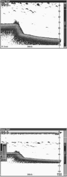
Full Sonar Chart
This is the default mode used when the unit is turned on for the first time or when it’s reset to the factory defaults. The bottom signal scrolls across the screen from right to left. Depth scales on the right side of the screen aid in determining the depth of targets. The line at the top of the screen represents the surface.The bottom depth and surface tempera-
ture (if equipped with a temperature sensor) show at the top left corner of the screen. The FasTrak™ display shows just to the right of the scale. This changes all echoes into short horizontal bars, replicating a flasher sonar. The zoom bar on the far right shows the area that’s zoomed when the zoom is in use. (See the Zoom section for more information.) The frequency of the transducer in use shows at the bottom of the screen.
9
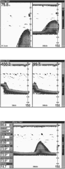
Split Zoom Sonar Chart
A split chart shows the underwater world from the surface to the bottom on the right side of the screen. The left side shows an enlarged version of the right side. The zoom range shows at the bottom left corner of the screen. In this example, the zoom range is 2X, or two times the right side’s view.
Split Frequency Sonar Chart
This chart shows sonar data from the 50 kHz transducer element (if equipped) on the left side of the screen, and data from the 200 kHz transducer element on the right. All features are the same as the Full Sonar Chart.
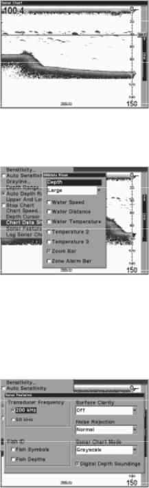
Digital/Chart
This mode shows the chart on the right side of the screen. The left side has seven large digital boxes containing the Water Depth at the top of the screen, (with the shallow and deep alarm settings immediately beneath the depth) Water Speed (from an optional speed sensor), Water Distance (distance travelled or log) also requires a speed sensor. Surface
Water Temperature, Temperature #2, Temperature #3, and input voltage. (Note: Temperature #2 and #3 require additional temperature sensors.)
10
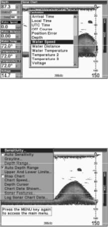
Customizing the Digital/Chart Screen
The Digital/Chart screen can be customized to show different digital data than the defaults shown on the screen at the bottom of page 8.To customize this screen, press the MENU key while the Digital/Chart screen is showing. Scroll down to the bottom of this menu to the Customize label and select it. The Water Speed bar flashes, signifying that the window can be changed. Press the
ENT key to show a menu of available options. Choose the data that you want shown at this location, then press the ENT key to select it.To change another, simply press the down arrow key. The ID bar will flash on the selected box. Repeat the above steps until you’re finished customizing. Press the EXIT key to stop the bar from flashing.
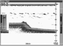
MENUS
This unit uses menus extensively to guide you through its functions and features. To use the menus, press the MENU key.
(Note: There are two “layers” of menus. Pressing the MENU key once brings up the first set of menus, pressing the menu key again brings up the second set.)
Use the arrow keys to navigate through the menus. Generally, to make a selection from a menu, highlight the desired item with the arrow keys, then press the ENT (enter) key. The EXIT key erases the menus.
Note: There is a mode that splits the screen in half, with the map on the left and the sonar on the right. This screen can be found in the Map/Map With Sonar page. When this screen is activated, you will have to specify which side the menu key corresponds to. To do this, press the PAGES key twice while the Map With Sonar screen is showing. The black bar at the top of the screen will begin flashing above either the map or the sonar. Use the arrow key to select the side that you wish to assign the MENU key to. Press the EXIT key when you’re finished. To reassign the menu key, repeat the above steps.
11
SONAR OPTIONS Sensitivity
The sensitivity controls the ability of the unit to pick up echoes. A low sensitivity level excludes much of the bottom information, fish signals, and other target information. High sensitivity levels let you see this detail, but it can also clutter the screen with many undesired signals. Typically, the best sensitivity level shows a good solid bottom signal with Grayline and some surface clutter.
The sensitivity is adjusted to keep a solid bottom signal displayed, plus a little more when the unit is in the automatic mode. This gives it the capability to show fish and other detail.
However, situations occur where it becomes necessary to increase or decrease the sensitivity. This typically happens when you wish to see more detail, so an increase in sensitivity is indicated. The procedure to adjust it is the same whether the unit is in the automatic or manual mode.
To adjust the sensitivity, press the MENU key, then select “Sensitivity”. The screen at right appears. The sensitivity control has a vertical adjustment bar. The number at the bottom of the bar shows the percentage of sensitivity in use.
To increase the sensitivity level, press the up arrow key. As you press the key, the control knob
will move upward and the percentage will increase in value.You can also see the difference on the chart record as it scrolls. When the sensitivity is at the desired level, release the key.
To decrease the sensitivity level, press the down arrow key. The control knob will move downward and the percentage will decrease. When the sensitivity is at the desired level, release the key. When you reach either the maximum or minimum limit, a tone sounds.
To erase the menu, press the EXIT key.
Automatic Sensitivity
The unit can adjust the sensitivity for you. It bases the sensitivity level on water depth and conditions. To turn this on, press the MENU key, then
12
select “Auto Sensitivity” and press the ENT key. To turn it off, repeat the above steps. Press the EXIT key to erase the menu.
GRAYLINE®
GRAYLINE lets you distinguish between strong and weak echoes. It “paints” gray on targets that are stronger than a preset value. This allows you to tell the difference between a hard and soft bottom. For example, a soft, muddy or weedy bottom returns a weaker signal which is shown with a narrow or no gray line. A hard bottom returns a strong signal which causes a wide gray line.
If you have two signals of equal size, one with gray and the other without, then the target with gray is the stronger signal. This helps distinguish weeds from trees on the bottom, or fish from structure.
GRAYLINE is adjustable. Since GRAYLINE shows the difference between strong and weak signals, adjusting the sensitivity may
require a different GRAYLINE level, also. The level chosen by the unit at power on is usually adequate for most conditions. Experiment with your unit to find the GRAYLINE setting that’s best for you.
To adjust the GRAYLINE level, press the MENU key, then select “Grayline”. The screen above appears. Use the up or down arrow keys to adjust the gray level. You can see the change on the chart record as you press the keys. After you’ve finished, press the EXIT key to erase the menu.
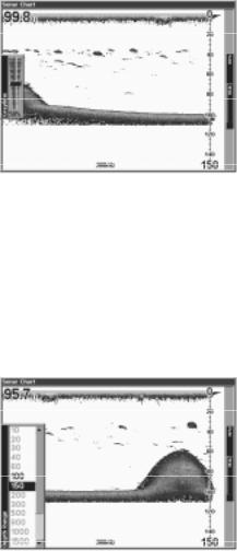
RANGE - Automatic
When turned on for the first time, the bottom signal is automatically placed in the lower half of the screen.This is called Auto Ranging and is part of the automatic function. However, depending upon the bottom depth and the current range, you can change the range to a different depth. To do this, press the MENU key, then select “Depth Range”.The screen
at right appears. Press the up or down arrow keys to select a different
13
range that’s highlighted. The range numbers that are gray cannot be selected. When you’re finished, press the EXIT key to erase the menu.
RANGE - Manual
You have complete control over the range when the unit is in the manual mode.
To change the range, first turn the automatic depth range off by pressing the MENU key, then selecting “Auto Depth Range”, then press the ENT key to turn it off. Next, select “Depth Range”. Press the up or down arrow keys to select a different range.The available ranges are 0-10, 20, 30, 40, 60, 100, 150, 200, 300, 500, 800, 1000, 1500, 2000, and 3000 feet. After selecting the range, press the EXIT key to erase the range menu.
NOTE: The sonar’s depth capability depends on the transducer installation, water and bottom conditions, and other factors.
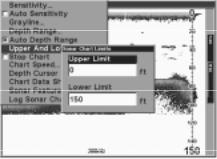
RANGE - Upper and Lower Limits
Virtually any segment of the water can be displayed by using the upper and lower limit feature. This lets you pick the shallow and deep range limits that are shown on the screen, provided there is at least ten feet between the upper and lower limit. For example, a range from 12 feet to 34 feet.
To change the upper and lower limits, press the MENU key, then select “Upper and Lower Limits”. A screen similar to the one at right appears. Upper Limit is highlighted.To select it, press the ENT key. To select the lower limit, press the down arrow key to highlight it, then press the ENT key. Once a limit window is selected, the range inside the window
changes to zeros. Use the arrow keys to both select and change the numbers in the window. Press the ENT key to accept the change. Press the EXIT key when you’re finished. The Upper and Lower Limit menu erases and the unit begins scrolling echoes across the screen using the new range values.
Changing the upper and lower limits gives you far greater control over the range. This feature lets you “zoom” the display in virtually unlimited combinations. Virtually any segment of the water, from the surface to the bot-
14
tom can be shown, which enlarges targets to best suit your fishing needs and water conditions.
ZOOM
“Zooming” the display is a common method used to enlarge small detail, fish signals, and the bottom with its asscociated structure. This unit lets you zoom the display quickly and easily by pressing the ZIN key. Pressing it once doubles the size (2X) of all echoes on the screen. Pressing it again quadruples the size of the echoes (4X).The zoom bar on the
far right side of the screen shows which echoes will be displayed on the screen when the ZIN key is pressed. For example, pressing the ZIN key once will enable a 2X zoom which will show all echoes that are between the top and bottom of the 2X zoom bar. Pressing the key again will give a 4X zoom and only the echoes between the top and bottom of the 4X bar will show on the screen.
Press the ZOUT key to return the display to the normal mode.
STOP CHART
To temporarily stop the chart from scrolling, press the MENU key, then select “Stop Chart” from the menu and press the ENT key. Repeat these steps to start the chart again.
CHART SPEED
The rate that echoes scroll across the screen is called the chart speed. It’s adjustable by pressing the MENU key, then selecting “Chart Speed”. A sliding knob adjustment appears on the screen. The default is maximum. Press the up or down arrow key to adjust the speed, then press the EXIT key to erase the menu.
DEPTH CURSOR
The depth cursor consists of a horizontal line with a digital depth box on the right side. The numbers inside the box show the depth of the cursor.
15
The cursor can be moved to any location on the screen, letting you pinpoint the depth of a target.
To show the depth cursor, press the MENU key, then select “Depth Cursor”. Press the ENT key. The cursor appears at the top of the screen. Use the arrow keys to move the cursor to the desired depth.
Erase the depth cursor by pressing the EXIT key.
CHART DATA
The digital information shown in the upper left corner of the display along with the zone alarm and zoom bar can be changed using the Chart Data menu. To use this menu, press the MENU key, select “Chart Data Shown” and press the ENT key. A screen similar to the one at right appears.
The unit can show the digital
depth in large numbers (default), small numbers, or off. To change it, select the “Depth” label, then press the ENT key. Highlight the desired setting using the arrow keys, then press the ENT key.
To change any of the other settings, on this screen, select them using the arrow keys, then press the ENT key to select them. Press the EXIT key to erase the menu when you’re finished.
SONAR FEATURES
Several key sonar options are under the “Sonar Features” menu on the main menu. Select the main menu by pressing the MENU key, then select “Sonar Features” and press the ENT key. The menu shown at right appears.
16
Transducer Frequency
This unit operates from both 200 kHz and 50 kHz. The default frequency is 200 kHz. It’s best for use in shallow water. The 50 kHz frequency is best for deep water, especially saltwater. Use the arrow keys to highlight the desired frequency, then press the ENT key to select it.
Surface Clarity
The markings extending downward from the zero line on the chart are called “surface clutter”. These markings are caused by wave action, boat wakes, temperature inversion, and more.
The surface clarity control reduces or eliminates surface clutter signals from the display. It does this by changing the sensitivity of the receiver, decreasing it near the surface and gradually increasing it as the depth increases. The maximum depth that the surface clarity control can affect is 75% of the selected depth range. For example, on a 0 - 60 foot range with surface clarity control set to high, surface clutter will be reduced down to 45 feet.
There are three levels of surface clarity available: low, medium, or high. It can also be turned off. The default level is low. To change it, highlight “Surface Clarity” on the “Sonar Features” menu, then press the ENT key to select it. Use the cursor keys to highlight the desired level of surface clarity, then press the ENT key.
Noise Rejection
The automatic noise rejection system built into this unit constantly evaluates the effects of boat speed, water conditions, and interference from electrical and mechanical sources such as bilge pumps, engine ignition systems and wiring, even engine vibration. It then works to reduce or eliminate the negative effects on the sonar screen. This gives the best display possible under most conditions.
The Noise Rejection system is an effective tool in combating noise. In sonar terms, noise is any undesired marks on the display.
This unit has two levels of noise rejection: normal and high. It can also be turned off. The default is normal. To change it, highlight “Noise Rejection” on the “Sonar Features” menu, then press the ENT key to select it. Use the cursor keys to highlight the desired level of noise rejection, then press the ENT key.
17
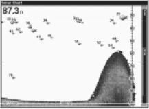
SONAR FEATURES (cont.) Fish Symbols
The Fish Symbols feature identifies targets that meet certain conditions as fish. The microcomputer analyses all echoes and eliminates surface clutter, thermoclines, and other signals that are undesirable. In most instances, remaining targets are fish. The Fish Symbols feature displays symbols on the screen in place of the actual fish echoes.
There are several fish symbol sizes. These are used to designate the relative size between targets. In other words, it displays a small fish symbol when it thinks a target is a small fish, a medium fish symbol on a larger target, etc.
The microcomputer is sophisticated, but it can be fooled. It can’t distinguish between fish and other suspended objects such as trotlines, turtles, submerged floats, air bubbles, etc. Individual tree limbs extending outwards from a group of limbs is the hardest object for the Fish Symbols feature to distinguish from fish.
You may see Fish Symbols symbols on the screen when actually, there are no fish. Practice with the unit in both the Fish Symbols mode and without to become more familiar with the Fish Symbols feature.
The default for Fish Symbols is off. To turn the Fish Symbols feature on, highlight “Fish Symbols” on the “Sonar Features” menu. Press the ENT key to turn the Fish Symbols feature on. Any targets the microcomputer determines are fish will be displayed as fish symbols.
Fish Depths
The Fish Depths feature shows the depth of a fish symbol when it appears on the display. This lets you accurately gauge the depth of targets. This feature is available only when the Fish Symbols feature is on.
The default for Fish Depths is off. To turn the this feature on, highlight “Fish Depths” on the “Sonar Features” menu. Press the ENT key to turn the Fish Depths feature on. (Note: If Fish Symbols is off, turning Fish Depths on will also turn Fish Symbols on.)
18
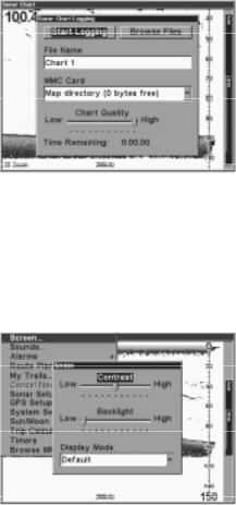
LOG SONAR CHART DATA
If you have a MMC installed in the unit, the sonar data shown on the screen can be saved to the MMC. This can be played back at any time.
To save the chart data, press the MENU key, then select “Log Sonar Chart Data”. The screen at right appears.
To save data using the defaults on this screen, highlight “Start Logging” and press the ENT key.You can change any of the defaults on this screen, if desired. When finished, press the EXIT key.
DISPLAY SETTINGS Contrast/Backlight/Display Mode
To adjust these settings, press the MENU key twice. This shows the second menu page. Highlight “Screen” at the top of the page and press the ENT key. The screen at right appears.
Contrast is highlighted on this menu by default. To adjust it, press the ENT key and use the left or right arrow keys to change it. Press the ENT key when finished.
To adjust the backlighting’s brightness, first turn it on by pressing the PWR key. Next, highlight the “Backlight” label, then use the arrow keys to adjust it. Press the ENT key when you’re finished.
Display Mode optimzes the LCD (liquid crystal display) for specific viewing conditions. Normally, it should stay in the default mode. However, the High Contrast mode may be useful for shaded light conditions and the Night Viewing mode for use at night. Select the “Display Mode” menu, press the ENT key, then select the desired setting from the drop-down menu. Press the ENT key when you’re finished.
19
 Loading...